La page est en cours de chargement...

Defender II
SAFETY NOTICE:
If this heater is not properly installed, a house re may result.
For your safety, follow the installation instructions. Never
use make-shift compromises during the installation of this
heater. Contact local building or re ofcials about permits,
restrictions and installation requirements in your area.
CAUTION!
Please read this entire manual before you install or use your
new room heater. Failure to follow instructions may result in
property damage, bodily injury, or even death. Improper
Installation Could Void Your Warranty!
Save these instructions. This manual will help you to obtain
efcient, dependable service from the heater, and enable
you to order repair parts correctly. Keep in a safe place for
future reference.
853363-0204i
CALIFORNIA PROPOSITION 65 WARNING:
This product can expose you to chemicals including carbon monoxide, which
is known to the State of California to cause cancer, birth defects and/or other
reproductive harm. For more information, go to www.P65warnings.ca.gov
Ce produit peut vous exposer à des produits chimiques, y compris le
monoxyde de carbone, qui est connu dans l'État de Californie pour causer
le cancer, des malformations congénitales et / ou d'autres problèmes de
reproduction. Pour plus d'informations, visitez www.P65warnings.ca.gov
Owner’s Manual Model: US1100E
U.S. Stove
227 Industrial Park Rd. South
Pittsburg, TN 37380, USA Phone:
(800)750-2723 www.usstove.com
Tested Per EPA Methods ALT-125, ASTM
E2515, ASTM E3053 and CSA B415
Certied to UL 1482-2011 (R2015) and
ULC-S627-00 (R2016)
Approved for mobile home installation
in USA and Canada
U.S. Environmental Protection Agency
Certied to comply with 2020
particulate emissions standards.
Report Number: F19-473
R

-2-
This manual describes the installation and operation of the Defender II, US1100E wood heater. This heater meets
the 2020 U.S. Environmental Protection Agency’s cordwood emission limits for wood heaters sold after May 15,
2020. Under specic test conditions this heater has been shown to deliver heat at rates ranging from 15,196 to
40,594 Btu/hr. Note: The BTU ratings mentioned above are based on the EPA test protocol under specic test
conditions. Our advertised BTU’s are based on the rst hour of operation at high burn rate burning dry cordwood.
CAUTIONS:
• HOT WHILE IN OPERATION. KEEP CHILDREN, CLOTHING AND FURNITURE AWAY. CONTACT MAY CAUSE SKIN
BURNS.
• DO NOT USE CHEMICALS OR FLUIDS TO IGNITE THE FIRE.
• DO NOT LEAVE THE STOVE UNATTENDED WHEN THE DOOR IS SLIGHTLY OPENED.
• DO NOT BURN GARBAGE, FLAMMABLE FLUID SUCH AS GASOLINE, NAPHTHA OR MOTOR OIL.
• DO NOT CONNECT TO ANY AIR DISTRIBUTION DUCT OR SYSTEM.
• ALWAYS CLOSE THE DOOR AFTER THE IGNITION.
Combustible: Wood
Colors: Metallic Black
Flue Pipe Diameter: 6” (153 mm)
Flue Pipe Type: (Standard Single Wall or Double Wall): Black or Blued Steel 2100°F (650°C)
Minimum Chimney Height: 12’ (3.7 m)
Maximum Log Length: 18” (458 mm)
Electrical: 120VAC, 0.55A, 60Hz
Dimensions
Overall:
Depth x Width x Height:
21.5” x 22.5” x 29.25”
(547 mm X 572 mm X 743 mm)
Combustion Chamber:
Width x Depth:
18.25” x 11.5” (464 mm X 293 mm)
Firebox Volume:
Cubic Feet:
1.35ft
3
Door Opening: Width x Height: 16” x 9” (407 mm X 229 mm)
Pyroceramic Glass Door: (Viewing) Width x Height: 15” x 8” (381 mm X 204 mm)
Weight (lbs): 180 lbs
UNPACK AND INSPECT
Remove the packing from the appliance and inspect for any damage. Your appliance is packed with the door
handle spring not installed. Ensure that the bricks are positioned correctly and not broken (see illustration for
proper brick arrangement). Make sure that the bafe board, above the air tubes, is in place and undamaged.
(DO NOT REMOVE).
Brick Conguration
Note: Register your product on line at www.usstove.com. Save your receipt with your records for any claims.

-3-
Step 1 - THE BLOWER ASSEMBLY MUST BE DISCONNECTED FROM THE SOURCE OF ELECTRICAL SUPPLY BEFORE
ATTEMPTING THE INSTALLATION. With pliers, cut the 4 tabs and remove panel on the back of the stove. Note:
Discard the panel.
Step 2 - Fix the assembly to the back of the stove with the four screws provided. THE BLOWER ASSEMBLY IS
INTENDED FOR USE ONLY WITH A STOVE THAT IS MARKED TO INDICATE SUCH USE. DO NOT ROUTE THE SUPPLY CORD
NEAR OR ACROSS HOT SURFACES!
Assembly
Installation
SAFETY NOTICE
• IF THIS STOVE IS NOT PROPERLY INSTALLED, A HOUSE FIRE MAY RESULT. TO REDUCE THE RISK OF FIRE, FOLLOW
THE INSTALLATION INSTRUCTIONS.
• CONSULT YOUR MUNICIPAL BUILDING DEPARTMENT OR FIRE OFFICIALS ABOUT PERMITS, RESTRICTIONS AND
INSTALLATIONS REQUIREMENTS IN YOUR AREA.
• USE SMOKE DETECTORS IN THE ROOM WHERE YOUR STOVE IS INSTALLED.
• KEEP FURNITURE AND DRAPES WELL AWAY FROM THE STOVE.
• NEVER USE GASOLINE, GASOLINE-TYPE LANTERN FUEL, KEROSENE, CHARCOAL LIGHTER FLUID, OR SIMILAR
LIQUIDS TO START OR “FRESHEN UP” A FIRE IN THIS HEATER. KEEP ALL SUCH LIQUIDS WELL AWAY FROM THE
HEATER WHILE IT IS IN USE.
• IN THE EVENT OF A CHIMNEY FIRE, PUSH THE AIR CONTROL FULL CLOSED TO DEPRIVE THE FIRE OF OXYGEN.
CALL THE FIRE DEPARTMENT.
• DO NOT CONNECT TO ANY AIR DISTRIBUTION DUCT OR SYSTEM.
• A SOURCE OF FRESH AIR INTO THE ROOM OR SPACE HEATED SHALL BE PROVIDED WHEN REQUIRED.
• ONLY OPERATE THE STOVE WITH THE DOOR CLOSED. OPERATING WITH THE DOOR OPEN COULD CAUSE
OVERFIRING.
POSITIONING THE STOVE
It is very important to position the wood stove as close as possible to the chimney, and in an area that will favor
the most efcient heat distribution possible throughout the house. The stove must, therefore, be installed in the
room where the most time is spent and in the most spacious room possible. Recall that wood stoves produce
radiating heat, the heat we feel when we are close to a wood stove. A wood stove also functions by convection,
that is through the displacement of hot air accelerated upwards and its replacement with cooler air. If necessary,
the hot air distribution from the stove may be facilitated by the installation of a blower. Route power cord away
from unit. Do not route power cord under or in front of appliance. The wood stove must not be hooked up to a
hot air distribution system since an excessive accumulation of heat may occur.
FLOOR PROTECTOR
This heater must have a non-combustible oor protector (ember protection) installed beneath it if the oor is
of combustible material. If a oor pad is used, it should be UL listed or equal. The oor pad or non-combustible
surface should be large enough to extend under the stove and beyond each side as indicated. If there is a
horizontal run of ue pipe, there needs to be oor protection under it that extends two inches beyond either side
of the pipe.

-4-
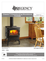
FLOOR PROTECTOR DIMENSIONS
H
J
K
L
M
N
P
Q
Key Dimension Inch mm
H Stove Width 22.48 571
J Stove Depth 20.76 528
*K Front 16 407
L Back 2 51
M Left 8 204
N Right 8 204
P Total Width 38.48 978
Q Total Length 38.76 985
* Canadian installations require 18” (457mm)
FREE STANDING STOVE CLEARANCES
A wood stove must never be installed in a hallway or near a staircase, since it may block the way in case of re
or fail to respect required clearances. It is of utmost importance that the clearances to combustible materials be
strictly adhered to during installation of the stove. Refer to the tables below:
• Do not place any combustible material within 4’ (1.2m) of the front of the unit.
• The clearance between the ue pipe and a wall are valid only for vertical walls and for vertical ue pipe.
• The chimney connector must not pass through an attic or roof space, closet or similar concealed space, a
oor, or a ceiling.
• For Canadian installations, where passage through a wall, or partition of combustible construction is desired,
the installation must conform to CAN/CSA-B365.
• A ue pipe crossing a combustible wall must have a minimum clearance of 18” (457.2mm).
• To reduce ue clearances from combustible materials, contact your local safety department.
Key Dimensions Inch mm
A Backwall to Stove 17 432
B Sidewall to Stove 21 534
C Wall to corner (Angled Installation) 14 356
D Ceiling Height 84 2134
E Backwall to Flue 20 508
F Sidewall to Flue 29 737
G Wall to Flue (Angled Installation) 22 559
CLEARANCE TO WALLS
Side wall
Backwall
Side wall
Backwall
CORNER INSTALLATION
CLEARANCE TO WALLS
Ceiling
CORNER INSTALLATION
CLEARANCE TO
WALLS & CELING

-5-
SPECIAL MOBILE HOME REQUIREMENTS
WARNING! - Do not install in a sleeping room
CAUTION! - The structural integrity of the mobile home oor, wall, and ceiling/roof must be maintained.
In addition to the previously detailed installation requirements, mobile home installations must meet the following
requirements:
• The space heater is to be connected to a factory-built chimney conforming to CAN/ULC-S629, Standard for
650°C Factory-Built Chimneys.
• The heater must be permanently attached to the oor. There are two holes in the pedestal base, use 3/8”
bolts through the oor.
• The heater must be electrically grounded to the steel chassis of the mobile home with 8 GA copper wire
using a serrated or star washer to penetrate paint or protective coating to ensure grounding.
• When moving your mobile home, all exterior venting must be removed while the mobile home is being
relocated. After relocation, all venting must be reinstalled and securely fastened.
• Outside Air is mandatory for mobile home installation. See your dealer for purchasing.
• Check with your local building ofcials as other codes may apply.
• Only use the specied components listed in this manual for this unit. The use of components that are not
meant for this unit can cause unsafe conditions.
COMBUSTION AIR ASSEMBLY INSTRUCTIONS
This appliance requires a source of combustion air. If your home is of tight construction or has negative pressure
problems, you will need an outside source of air. Below is a list of possible indicators that a source of outside
combustion air may be required.
MOBILE HOME INSTALLATIONS - REQUIRED
• Your stove does not draw steadily, smoke rollout occurs, wood burns poorly, or back-drafts occur whether or
not there is combustion present.
• Existing fuel-red equipment in the house, such as replaces or other heating appliances, smell, do
not operate properly, suffer smoke roll-out when opened, or back-drafts occur whether or not there is
combustion present.
• Opening a window slightly on a calm (windless) day alleviates any of the above symptoms.
• The house is equipped with a well-sealed vapor barrier and tight tting windows and/or has any powered
devices that exhaust house air.
• There is excessive condensation on windows in the winter.
• A ventilation system is installed in the house.
If an outside air intake is required, you may purchase a standard 4” Dryer Vent kit from your local hardware
supply store and install it on the rear of the appliance.
When using a Dryer venting kit, the outlet cover must be of a design that DOES NOT close by means of a ap
or trap door. You must purchase a style that allows a continuous in-ow of air and that has a rodent screen. This
adapter can be purchased from your dealer.
4FAK INSTALLATION
Follow the manufacturer’s installation instructions for attaching the dryer vent kit to the home. Then, attach it to
the adapter on the combustion air inlet on the back of the pedestal as shown.
“Dryer Venting Kit”
Installation
Slide the hose clamp over the aluminium ex pipe. Then slide the ex pipe
over the air intake tube of the stove. Next tighten the hose clamp over the
end of the aluminium ex hose.

-6-
CHIMNEY CONNECTOR (STOVE PIPE)
Your chimney connector and chimney must have the same diameter as the stove outlet (6”). If this is not the
case, we recommend you contact your dealer in order to insure there will be no problem with the draft.
The stove pipe must be made of aluminized or cold roll steel with a minimum thickness of 0.021” or 0.53 mm. It is
strictly forbidden to use galvanized steel.
Your smoke pipe should be assembled in such a way that the male section (crimped end) of the pipe faces
down. Attach each of the sections to one another with three equidistant metal screws. Seal with furnace cement.
The pipe must be short and straight. All sections installed horizontally must slope at least 1/4 inch per foot, with
the upper end of the section toward the chimney. Any installation with a horizontal run of chimney pipe must
conform to NFPA 211. You may contact NFPA (National Fire Protection Association) and request the latest edition
of the NFPA Standard 211.
To insure a good draft, the total length of the coupling pipe should never exceed 8’ to 10’ (2.4m to 3.04 m).
(Except for cases of vertical installation, cathedral-roof style where the smoke exhaust system can be much
longer and connected without problem to the chimney at the ceiling of the room).
There should never be more than two 90 degrees elbows in the smoke exhaust system.
Installation of a “barometric draft stabilizer” (replace register) on a smoke exhaust system is prohibited.
Furthermore, installation of a draft damper is not recommended. Indeed, with a controlled combustion wood
stove, the draft is regulated upon intake of the combustion air in the stove and not at the exhaust.
IMPORTANCE OF PROPER DRAFT
Draft is the force which moves air from the appliance up through the chimney. The amount of draft in your
chimney depends on the length of the chimney, local geography, nearby obstructions and other factors. Too
much draft may cause excessive temperatures in the appliance and may cause damage. Inadequate draft
may cause backpufng into the room and ‘plugging’ of the chimney.
Inadequate draft will cause the appliance to leak smoke into the room through appliance and chimney
connector joints. An uncontrollable burn or excessive temperature indicates excessive draft.
To
Appliance

-7-
CHIMNEY
Your wood stove may be hooked up with a 6” factory built or masonry chimney. If you are using a factory built
chimney, it must comply with UL 103 or CSA-B365 standard; therefore it must be a Type HT (2100°F). It is extremely
important that it be installed according to the manufacturer’s specications. Take into account the chimney’s
location to insure it is not too close to neighbors or in a valley which may cause unhealthy or nuisance conditions.
If you are using a masonry chimney, it is important that it be built in compliance with the specications of the
National Building Code. It must be lined with re clay bricks, metal or clay tiles sealed together with re cement.
(Round ues are the most efcient).
The interior diameter of the chimney ue must be identical to the stove smoke exhaust. A ue which is too
small may cause draft problems, while a large ue favours rapid cooling of the gas, and hence the build-up of
creosote and the risk of chimney res. Note that it is the chimney and not the stove which creates the draft effect;
your stove’s performance is directly dependent on an adequate draft from your chimney.
The following recommendations may be useful for the installation of your chimney:
1. Do not connect this unit to a chimney ue serving another appliance.
2. It must rise above the roof at least 3’ (0.9m) from the uppermost point of contact.
3. The chimney must exceed any part of the building or other obstruction within a 10’ (3.04m) distance by a
height of 2’ (0.6m).
4. Installation of an interior chimney is always preferable to an exterior chimney. Indeed, the interior chimney
will, by denition, be hotter than an exterior chimney, being heated up by the ambient air in the house.
Therefore the gas which circulates will cool more slowly, thus reducing the build-up of creosote and the risk
of chimney res.
The draft caused by the tendency for hot air to rise will be increased with an interior chimney.
Using a re screen at the extremity of the chimney requires regular inspection in order to insure that it is not
obstructed thus blocking the draft, and it should be cleaned when used regularly.
Exterior chimney should be double or triple wall.

-8-
MASONRY CHIMNEY
Ensure that a masonry chimney meets the minimum standards of the National Fire Protection Association (NFPA)
by having it inspected by a professional. Make sure there are no cracks, loose mortar or other signs of deterioration
and blockage. Have the chimney cleaned before the stove is installed and operated. When connecting the
stove through a combustible wall to a masonry chimney, special methods are needed.

-9-
FACTORY BUILT CHIMNEY
When a metal prefabricated chimney is used, the manufacturer’s installation instructions must be followed. You
must also purchase (from the same manufacturer) and install the ceiling support package or wall pass-through
and “T” section package, restops (where needed), insulation shield, roof ashing, chimney cap, etc. Maintain
proper clearance to the structure as recommended by the manufacturer. The chimney must be the required
height above the roof or other obstructions for safety and proper draft operation.

-10-
Method A. 12” (304.8 mm) Clearance to Combustible Wall
Member: Using a minimum thickness 3.5” (89 mm) brick and a
5/8” (15.9 mm) minimum wall thickness clay liner, construct a
wall pass-through. The clay liner must conform to ASTM C315
(Standard Specication for Clay Fire Linings) or its equivalent.
Keep a minimum of 12” (304.8 mm) of brick masonry between the
clay liner and wall combustibles. The clay liner shall run from the
brick masonry outer surface to the inner surface of the chimney
ue liner but not past the inner surface. Firmly grout or cement the
clay liner in place to the chimney ue liner.
Method B. 9” (228.6 mm) Clearance to Combustible Wall
Member: Using a 6” (152.4 mm) inside diameter, listed, factory-
built Solid-Pak chimney section with insulation of 1” (25.4 mm) or
more, build a wall pass-through with a minimum 9” (228.6 mm) air
space between the outer wall of the chimney length and wall
combustibles. Use sheet metal supports fastened securely to wall
surfaces on all sides, to maintain the 9” (228.6 mm) air space.
When fastening supports to chimney length, do not penetrate
the chimney liner (the inside wall of the Solid-Pak chimney). The
inner end of the Solid-Pak chimney section shall be ush with the
inside of the masonry chimney ue, and sealed with a non-water
soluble refractory cement. Use this cement to also seal to the
brick masonry penetration.
Method C. 6” (152.4 mm) Clearance to Combustible Wall
Member: Starting with a minimum 24 gage (.024” [.61 mm]) 6”
(152.4 mm) metal chimney connector, and a minimum 24 gage
ventilated wall thimble which has two air channels of 1” (25.4 mm)
each, construct a wall pass-through. There shall be a minimum 6”
(152.4) mm separation area containing berglass insulation, from
the outer surface of the wall thimble to wall combustibles. Support
the wall thimble, and cover its opening with a 24-gage minimum
sheet metal support. Maintain the 6” (152.4 mm) space. There
should also be a support sized to t and hold the metal chimney
connector. See that the supports are fastened securely to wall
surfaces on all sides. Make sure fasteners used to secure the metal
chimney connector do not penetrate chimney ue liner.
Method D. 2” (50.8 mm) Clearance to Combustible Wall
Member: Start with a solid-pak listed factory built chimney section
at least 12” (304 mm) long, with insulation of 1” (25.4 mm) or more,
and an inside diameter of 8” (2 inches [51 mm] larger than the
6” [152.4 mm] chimney connector). Use this as a pass-through for
a minimum 24-gauge single wall steel chimney connector. Keep
solid-pak section concentric with and spaced 1” (25.4 mm) off
the chimney connector by way of sheet metal support plates at
both ends of chimney section. Cover opening with and support
chimney section on both sides with 24 gage minimum sheet metal
supports. See that the supports are fastened securely to wall
surfaces on all sides.
NOTES:
Connectors to a masonry chimney, excepting method B, shall extend in one continuous section through the
wall pass-through system and the chimney wall, to but not past the inner ue liner face.
A chimney connector shall not pass through an attic or roof space, closet or similar concealed space, or a oor,
or ceiling.
COMBUSTIBLE WALL CHIMNEY CONNECTOR PASS-THROUGHS

-11-
TYPE
WEIGHT
(LBS. CU. FT.,
DRY)
PER CORD
EFFICIENCY
RANKING
SPLITS
MILLIONS
BTU’s/CORD
Hickory 63 4500 1.0 Well 31.5
White Oak 48 4100 .9 Fair 28.6
Red Oak 46 3900 .8 Fair 27.4
Beech 45 3800 .7 Hard 26.8
Sugar Maple 44 3700 .6 Fair 26.2
Black Oak 43 3700 .6 Fair 25.6
Ash 42 3600 .5 Well 25.0
Yellow Birch 40 3400 .4 Hard 23.8
Red Maple 38 3200 .3 Fair 22.6
Paper Birch 37 3100 .3 Easy 22.1
Elm/
Sycamore
34 2900 .2 Very Difcult 20.1
Red Spruce 29 1800 .1 Easy 16.1
WOOD UTILIZATION
Your heating unit was designed to burn wood only, no other materials should be burned. Waste and other
ammable materials should not be burned in your stove. Any type of wood may be used in your stove, but
specic varieties have better energy yields than others. Please consult the following table in order to make the
best possible choice. This heater is designed to burn natural wood only. Higher efciencies and lower emissions
generally result when burning air dried seasoned hardwoods, as compared to softwoods or to green or freshly
cut hardwoods.
DO NOT BURN:
1. Garbage;
2. Lawn clippings or yard waste;
3. Materials containing rubber, including tires;
4. Materials containing plastic;
5. Waste petroleum products, paints or paint thinners,
or asphalt products;
6. Materials containing asbestos;
7. Construction or demolition debris;
8. Railroad ties or pressure-treated wood;
9. Manure or animal remains;
10. Salt water driftwood or other previously salt water
saturated materials;
11. Unseasoned wood; or
12. Paper products, cardboard, plywood, or
particleboard. The prohibition against burning
these materials does not prohibit the use of re
starters made from paper, cardboard, saw dust,
wax and similar substances for the purpose of
starting a re in an affected wood heater.
Burning these materials may result in release of toxic fumes or render the heater ineffective and cause smoke.
Dead wood lying on the forest oor should be considered wet, and requires full seasoning time. Standing dead
wood can usually be considered to be about 2/3 seasoned. Splitting and stacking wood before it is stored
accelerates drying time. Storing wood on an elevated surface from the ground and under a cover or covered
area from rain or snow also accelerates drying time. A good indicator if wood is ready to burn is to check the
piece ends. If there are cracks radiating in all directions from the center then the wood should be dry enough
to burn. If your wood sizzles in the re, even though the surface is dry, it may not be fully cured, and should be
seasoned longer.
Do not burn manufactured logs made of wax impregnated sawdust or logs with
any chemical additives. Manufactured logs made of 100% compressed sawdust
can be burned, but be careful burning too much of these logs at the same time.
Start with one manufactured log and see how the stove reacts. You can increase
the number of logs burned at a time to making sure the temperature never rises
higher than 475 °F (246 °C) on a magnetic thermometer for installation on single wall
stove pipes or 900 °F (482 °C) on a probe thermometer for installation on double
wall stove pipe. The thermometer should be placed about 18” (457 mm) above the
stove. Higher temperatures can lead to overheat and damage your stove.
Wood Operating Instructions

-12-
Primary Air Settings
(Slide Damper is located in center of stove under hearth
plate)
(Damper Adjustment: Pulling out on damper increases air)
Electric Blower Speed Setting (Variable)
(Blower is on High when turned “ON”, Rotate clockwise
until stop for “LOW”.)
Burn Rate Adjust Damper from fully closed Burn Time Blower Speed
Low Fully Closed @ 30 minutes Low
Medium 5/8” @ 30 minutes Low
High 1-1/8” All minutes High
It is EXTREMELY IMPORTANT that you use DRY WOOD only in your wood stove. The wood should have dried for 9
to 15 months, such that the humidity content (in weight) is reduced below 20% of the weight of the log. It is very
important to keep in mind that even if the wood has been cut for one, two or even more years, it is not necessarily
dry, if it has been stored in poor conditions. Under extreme conditions it may rot, instead of drying. This point
cannot be over stressed; the vast majority of the problems related to the operation of a wood stove is caused by
the fact that the wood used was too damp or has dried in poor conditions. These problems can be:
- ignition problems - creosote build-up causing chimney res
- low energy yield - blackened windows
- incomplete log combustion
Smaller pieces of wood will dry faster. All logs exceeding 6” in diameter should be split. The wood should not be
stored directly on the ground. Air should circulate through the cord. A 24” to 48” air space should be left between
each row of logs, which should be placed in the sunniest location possible. The upper layer of wood should be
protected from the elements but not the sides.
TESTING YOUR WOOD
When the stove is thoroughly warmed, place one piece of split wood (about ve inches in diameter) parallel to
the door on the bed of red embers. Keep the air control full open by pulling on it and close the door. If ignition
of the piece is accomplished within 90 seconds from the time it was placed in the stove, your wood is correctly
dried. If ignition takes longer, your wood is damp. If your wood hisses and water or vapor escapes at the ends
of the piece, your wood is soaked or freshly cut. Do not use this wood in your stove. Large amounts of creosote
could be deposited in your chimney, creating potential conditions for a chimney re.
TAMPER WARNING
This wood heater has a manufacturer-set minimum low burn rate that must not be altered. It is against federal
regulations to alter this setting or otherwise operate this wood heater in a manner inconsistent with operating
instructions in this manual.
THE FIRST FIRES
The fresh paint on your stove needs to be cured to preserve its quality. Once the fuel charge is properly ignited,
only burn small res in your stove for the rst four hours of operation. Never open the air control more than
necessary to achieve a medium burn rate. Make sure that there’s enough air circulation while curing the stove.
The odors could be smelled during the 3 or 4 rst res. Never start your stove outside. You will not be able to see
if you are over heating.
IGNITION
The top down method of re building is recommended for this appliance. After making sure that the stove air
intake controls are fully open (completely pull-out towards you), place the largest pieces of wood on the bottom,
laid in parallel and close together. Smaller pieces are placed in a second layer, crossways to the rst. A third layer
of still smaller pieces is laid crossways to the second, this time with some spaces between. Then a fourth layer of
loose, small kindling and twisted newspaper sheets tops off the pile. Before igniting the paper and kindling wood,
it is recommended that you warm up the chimney. This is done in order to avoid back draft problems often due
to negative pressure in the house. If such is the case, open a window slightly near the stove and twist together a
few sheets of newspaper into a torch. Light up this paper torch and hold it as close as possible to the mouth of
the pipe inside the combustion chamber to warm up the chimney. Once the updraft movement is initiated, you
are ready to ignite the stove by lighting the paper and kindling wood inside the combustion chamber. When you
have achieved a good bed of hot embers, we recommend the following burn procedures:

-13-
CAUTION: Never alter the damper slide or the adjustment range to increase ring for any reason. Doing so could result in
heater damage and will void your warranty.
HEATING
Controlled combustion is the most efcient technique for wood heating because it enables you to select the type
of combustion you want for each given situation. The wood will burn slowly if the wood stove air intake control is
adjusted to reduce the oxygen supply in the combustion chamber to a minimum. On the other hand, wood will
burn quickly if the air control is adjusted to admit a larger quantity of oxygen in the combustion chamber. Refer
to the primary air settings table for damper operation setting. Real operating conditions may give very different
results than those obtained during testing according to the species of wood used, its moisture content, the size
and density of the pieces, the length of the chimney, altitude and outside temperature.
WARNINGS
• NEVER OVERFIRE YOUR STOVE. IF ANY PART OF THE STOVE STARTS TO GLOW RED, OVER FIRING IS HAPPENING.
READJUST THE AIR INTAKE CONTROL AT A LOWER SETTING.
• THE INSTALLATION OF A LOG CRADLE OR GRATES IS NOT RECOMMENDED IN YOUR WOOD STOVE. BUILD FIRE
DIRECTLY ON FIREBRICK.
• NEVER PUT WOOD ABOVE THE FIREBRICK LINING OF THE FIREBOX.
• ATTEMPTS TO ACHIEVE HEAT OUTPUT RATES THAT EXCEED HEATER DESIGN SPECIFICATIONS CAN RESULT IN
PERMANENT DAMAGE TO THE HEATER.
EFFICIENCY
Efciencies can be based on either the lower heating value (LHV) or the higher heating value (HHV) of the fuel.
The lower heating value is when water leaves the combustion process as a vapor, in the case of woodstoves the
moisture in the wood being burned leaves the stove as a vapor. The higher heating value is when water leaves
the combustion process completely condensed. In the case of woodstoves this would assume the exhaust gases
are room temperature when leaving the system, and therefore calculations using this heating value consider
the heat going up the chimney as lost energy. Therefore, efciency calculated using the lower heating value of
wood will be higher than efciency calculated using the higher heating value. In the United States all woodstove
efciencies should be calculated using the higher heating value.
The best way to achieve optimum efciencies is to learn the burn characteristic of you appliance and burn well-
seasoned wood. Higher burn rates are not always the best heating burn rates; after a good re is established a
lower burn rate may be a better option for efcient heating. A lower burn rate slows the ow of usable heat out
of the home through the chimney, and it also consumes less wood.
VISIBLE SMOKE
The amount of visible smoke being produced can be an effective method of determining how efciently the
combustion process is taking place at the given settings. Visible smoke consist of unburned fuel and moisture
leaving your stove. Learn to adjust the air settings of your specic unit to produce the smallest amount of visible
smoke. Wood that has not been seasoned properly and has a high wood moisture content will produce excess
visible smoke and burn poorly.
RELOADING
Once you have obtained a good bed of embers, you should reload the unit. In order to do so, open the air
controls to maximum a few seconds prior to opening the stove’s door. Then proceed by opening the door very
slowly; open it one or two inches for 5 to 10 seconds, before opening it completely to increase the draft and thus
eliminate the smoke which is stagnant in a state of slow combustion in the stove. Then bring the red embers to
the front of the stove and reload the unit.
For optimal operation of your wood stove, we recommend you to operate it with a wood load approximately
equivalent to the height of re bricks. Do not stack wood higher than the rebrick.
It is important to note that wood combustion consumes ambient oxygen in the room .In the case of negative
pressure, it is a good idea to allow fresh air in the room, either by opening a window slightly or by installing a fresh
air intake system on an outside wall.
Creosote - Formation and Need for Removal - When wood is burned slowly, it produces tar and other organic
vapors, which combine with expelled moisture to form creosote. The creosote vapors condense in the relatively
cool chimney ue of a slow-burning re. As a result, creosote residue accumulates on the ue lining. When ignited
this creosote makes an extremely hot re. The chimney connector and chimney should be inspected at least
once every two months during the heating season to determine if a creosote build-up has occurred. If creosote
has accumulated (3mm or more), it should be removed to reduce the risk of a chimney re.

-14-
CAUTIONS:
ASHES COULD CONTAIN HOT EMBERS EVEN AFTER TWO DAYS WITHOUT OPERATING THE STOVE.
We strongly recommend that you install a magnetic thermometer on your smoke exhaust pipe, approximately
18” above the stove. This thermometer will indicate the temperature of your gas exhaust fumes within the smoke
exhaust system. The ideal temperature for these gases is somewhere between 275°F and 500°F. Below these
temperatures, the build-up of creosote is promoted. Above 500 degrees, heat is wasted since a too large quantity
is lost into the atmosphere.
TO PREVENT CREOSOTE BUILD UP
• Always burn dry wood. This allows clean burns and higher chimney temperatures, therefore less creosote
deposit.
• Leave the air control full open for about 5 min. every time you reload the stove to bring it back to proper
operating temperatures. The secondary combustion can only take place if the rebox is hot enough.
• Always check for creosote deposit once every two months and have your chimney cleaned at least once a
year.
If a chimney or creosote re occurs, close all dampers immediately. Wait for the re to go out and the heater to
cool, then inspect the chimney for damage. If no damage results, perform a chimney cleaning to ensure there is
no more creosote deposits remaining in the chimney.
OPERATIONAL TIPS
• Get the appliance hot and establish a good coal bed before adjusting to a low burn rate (this may take 30 minutes or
more depending on your wood)
• Use smaller pieces of wood during start-up and a high burn rate to increase the stove temperature
• Be considerate of the environment and only burn dry wood
• Burn small, intense res instead of large, slow burning res when possible
• Learn your appliance’s operating characteristics to obtain optimum performance
• Burning unseasoned wet wood only hurts your stoves efciency and leads to accelerated creosote buildup in your
chimney.
ASH DISPOSAL
Whenever ashes get 3 to 4 inches deep in your rebox or ash pan, and when the re has burned down and
cooled, remove excess ashes. Leave an ash bed approximately 1 inch deep on the rebox bottom to help
maintain a hot charcoal bed. Ashes should be placed in a metal container with a tight-tting lid. The closed
container of ashes should be placed on a noncombustible oor or on the ground, away from all combustible
materials, pending nal disposal. The ashes should be retained in the closed container until all cinders have
thoroughly cooled. It is strongly recommended that ashes in the metal container are taken outside immediately,
and are not stored within your home.
SOOT FORMATION AND NEED FOR REMOVAL
When wood is burned, the products of combustion combine with moisture to form a soot residue which
accumulates on the ue lining. When ignited, this soot makes an extremely hot re. The chimney connector and
chimney should be inspected at least once every two month during the heating season to determine if a soot
buildup has occurred. If soot has accumulated, it should be removed to reduce the risk of a chimney re.
SMOKE AND CO MONITORS
Burning wood naturally produces smoke and carbon monoxide(CO) emissions. CO is a poisonous gas when
exposed to elevated concentrations for extended periods of time. While the modern combustion systems in
heaters drastically reduce the amount of CO emitted out the chimney, exposure to the gases in closed or conned
areas can be dangerous. Make sure you stove gaskets and chimney joints are in good working order and sealing
properly to ensure unintended exposure. It is recommended that you use both smoke and CO monitors in areas
having the potential to generate CO. MAINTENANCE
Your wood stove is a high efciency stove and therefore requires little maintenance. It is important to perform
a visual inspection of the stove every time it is emptied, in order to insure that no parts have been damaged,
in which case repairs must be performed immediately. Inspect and clean the chimney and connector pipe
periodically for creosote buildup or obstructions.

-15-
GLASS
• Inspect and clean the glass regularly in order to detect any cracks. If you spot one, turn the stove off
immediately. Do not abuse the glass door by striking or slamming shut. Do not use the stove if the glass is
broken.
• If the glass on your stove breaks, replace only with the glass supplied from your heater dealer. Never
substitute other materials for the glass.
• To replace the glass, remove the screws retaining the glass mouldings inside the door. Remove the
mouldings and replace the damaged piece with a new one. Perform the procedure backwards after
replacing. When replacing the glass, you should change the glass gasket to make sure you keep it sealed.
• Never wash the glass with a product that may scratch. Use a specialized product, available in the stores
where wood stoves are sold. The glass should be washed only when cold.
GASKETING
It is recommended that you change the door gasket (which makes your stove door air tight) once a year, in order to
insure good control over the combustion, maximum efciency and security. To change the door gasket, simply remove the
damaged one. Carefully clean the available gasket groove, apply a high temperature silicone sold for this purpose, and
install the new gasket. You may light up your stove again approximately 24 hours after having completed this operation. This
unit’s door uses a 1” diameter rope gasket.
PAINT
Only clean your stove with a dry soft cloth that will not harm the paint nish. If the paint becomes scratched or damaged,
it is possible to give your wood stove a brand new look, by repainting it with a 1200° F heat resistant paint. For this purpose,
simply scrub the surface to be repainted with ne sand paper, clean it properly, and apply thin coats (2) of paint successively.
AIR TUBES
The air tubes assembled in this unit are designed to provide an accurate mix of secondary air to insure the highest efciency.
Any damage or deterioration of these tubes may reduce the efciency of combustion. The air tubes are held in position by
either screws or snap pins. Locate these to either side of the tube and remove to allow the tube to be removed and replaced.
WARNING: Never operate the stove without a gasket or with a broken one. Damage to the stove or even
house re may result.
WHITE /
BLANC
GREEN /
VERT
WHITE /
BLANC
BLACK /
NOIR
BLACK /
NOIR
BLACK /
NOIR
BLOWER
RHEOSTAT /
RHÉOSTAT DU
VENTILATEUR
BLOWER MOTOR
BLOWER SPECS: 120VAC, 60 Hz AC,0.55amp
/
MTEUR DU
VENTILATEUR
DÉTAILS TECHNIQUES: 120VAC, 60 Hz CA,0,55AMP
BLACK /
NOIR
BLACK /
NOIR
Optional B36 Blower Wiring Diagram
NOTICE: DO NOT ALLOW THE POWER
CORD TO TOUCH HOT SURFACES! KEEP
THE POWER CORD AT LEAST 12”/30.5CM
FROM THE STOVE OR PIPE SURFACES.
DANGER: SHOCK HAZARD DISCONNECT
POWER SOURCE BEFORE INSTALLATION AND
WHENEVER SERVICING BLOWER ASSEMBLY.
CAUTION: MOVING PARTS CAN CAUSE
INJURY. DO NOT OPERATE WITH COVER
REMOVED.
NOTICE: ANY REPLACEMENT WIRING
MUST HAVE EQUIVALENT INSULATION
AND TEMPERATURE RATING (105° C).

-16-
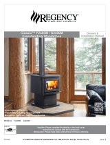
Replacement Parts
Key Part No. Description Qty
1 25089 Blower Housing Back 1
2 80442 80 Cfm Blower 1
3 80090 Rheostat W/Knob 1
4 25090 Blower Housing Front 1
5 80109 Strain Relief 1
6 80232 Supply Cord 1
Key Part No. Description Qty
1 29139 Air Deector 1
2 891824 Heatshield Weldment 1
3 40292A 6” Flue Collar 1
4 88042 1/4” Rope Gasket 1
5 29055 Ashpan 1
6 610923 Pedestal Weldment (US1100E-BP) 1
7 610928 Damper Weldment 1
8 86709 Damper Rod 1
9 891987 Plastic Knob 1
10 610918 Access Panel (US1100E-BP) 1
11 610944
Ashpan Housing Weldment
(US1100E-BL)
1
12 40566 Cast Iron Leg (US1100E-BL) 4
In order to maintain warranty, components must be replaced using original manufacturers parts purchased
through your dealer or directly from the appliance manufacturer. Use of third party components will void the
warranty.
1
2
3
4
5
6
6
11
12
10
5
3
4
2
1
7
8
9

-17-
Replacement Parts
In order to maintain warranty, components must be replaced using original manufacturers parts purchased
through your dealer or directly from the appliance manufacturer. Use of third party components will void the
warranty.
Key Part No. Description Qty.
1 893059 Wooden Thru Handle 1
2 893071 Door Handle 1
3 40887 Medium Arched Door 1
4 88324 1” Rope Gasket 1
5 893159 Clear Glass 1
6 29229 Glass Retainer, Sides 2
7 29227 Glass Retainer, Top 1
8 29230 Gasket Clamp 1
9 29228 Glass Retainer, Bottom 1
10 892294 Hinge Pin 2
3
1
2
4
5
6
7
8
9
10
Key Part No. Description Qty.
1 29039 Brick Retainer 1
2 29040 Brick Retainer 1
3 88315 Kao Wool Blanket 1
4 88147 Board, Ceramic Fiber 1
5 86904 Secondary Tube 1
6 891414 Half Firebrick 4
7 89066 Firebrick (4-1/2 X 9) 4
8 891095 Firebrick (6 X 8-1/4) 3
9 23783 Firebrick (1-1/4 X 2-9/16 X 9) 4
10 86903 Secondary Tube 1
11 86905 Secondary Tube 1
8
10
11
9
3
2
4
5
6
1
7

-18-
Notes

-19-
Notes

-20-
It is recommended that your heating system is serviced regularly and that the appropriate Service Interval
Record is completed.
SERVICE PROVIDER
Before completing the appropriate Service Record below, please ensure you have carried out the service
as described in the manufacturer’s instructions. Always use the manufacturer's specied spare part when
replacement is necessary.
Service Record
Service 01 Date: _____________________
Engineer Name: ________________________________
License No.: ____________________________________
Company: _____________________________________
Telephone No.: _________________________________
Stove Inspected: Chimney Swept:
Items Replaced: ________________________________
Service 03 Date: _____________________
Engineer Name: ________________________________
License No.: ____________________________________
Company: _____________________________________
Telephone No.: _________________________________
Stove Inspected: Chimney Swept:
Items Replaced: ________________________________
Service 05 Date: _____________________
Engineer Name: ________________________________
License No.: ____________________________________
Company: _____________________________________
Telephone No.: _________________________________
Stove Inspected: Chimney Swept:
Items Replaced: ________________________________
Service 07 Date: _____________________
Engineer Name: ________________________________
License No.: ____________________________________
Company: _____________________________________
Telephone No.: _________________________________
Stove Inspected: Chimney Swept:
Items Replaced: ________________________________
Service 02 Date: _____________________
Engineer Name: ________________________________
License No.: ____________________________________
Company: _____________________________________
Telephone No.: _________________________________
Stove Inspected: Chimney Swept:
Items Replaced: ________________________________
Service 04 Date: _____________________
Engineer Name: ________________________________
License No.: ____________________________________
Company: _____________________________________
Telephone No.: _________________________________
Stove Inspected: Chimney Swept:
Items Replaced: ________________________________
Service 06 Date: _____________________
Engineer Name: ________________________________
License No.: ____________________________________
Company: _____________________________________
Telephone No.: _________________________________
Stove Inspected: Chimney Swept:
Items Replaced: ________________________________
Service 08 Date: _____________________
Engineer Name: ________________________________
License No.: ____________________________________
Company: _____________________________________
Telephone No.: _________________________________
Stove Inspected: Chimney Swept:
Items Replaced: ________________________________
1/40