CREE LIGHTING CR-B Wireless (SC1_VDO_VRF) w-EB or GT Guide d'installation
- Taper
- Guide d'installation

CR-B Series with Wireless Technology
LED Luminaire With Emergency Backup (EB) and Generator Transfer Device (GTD)
Includes: CR14-B-(SC1,VDO/VRF)-(EB/GTD), CR22-B-(SC1,VDO/VRF)-(EB/GTD), CR24-B-(SC1,VDO/VRF)-(EB/GTD)
1x4, 2x2, 2x4 Luminaires
1 of 5 LPN05500X0004A0_A
INSTALLATION INSTRUCTIONS
INSTRUCTIONS D’INSTALLATION
• The CR-B Series of recessed troffers is for non-insulated ceiling applications using T-Bar ceiling grid, drywall grid adaptors, and surface mount
accessory kits.
• Designed for use in 120-277V 60 Hertz protected circuit (fuse box, circuit breaker). Supply wire sized as per NEC or governing code(s), 90° C
rated.
• NOTE: SmartCast luminaires must be installed on unswitched AC power. Constant power is required to maintain all luminaires on the SmartCast
network. If wall control or manual dimming is required, a SmartCast wall control dimmer must be used for manual on, off, and dimming.
IMPORTANT SAFEGUARDS
When using electrical equipment, basic safety precautions
should always be followed including the following:
READ AND FOLLOW ALL
SAFETY INSTRUCTIONS
1. DANGER- Risk of shock- Disconnect power before
installation.
DANGER - RISQUE DE CHOC - COUPER
L’ALIMENTATION AVANT L’INSTALLATION
2. CAUTION – Installation and servicing should be performed
by qualied personnel only. De-energize before opening.
ATTENTION – L’installation et l’entretien doivent être
eectués par du personnel qualié seulement. Mettre hors
tension avant l’ouverture
3. To reduce the risk of electric shock, disconnect both
standard and emergency power supplies and converter
connector of the emergency driver before servicing.
Pour réduire le risque de décharge électrique, vous devez
déconnecter à la fois le disjoncteur divisionnaire ou les
fusibles et les alimentations d’urgence avant l’entretien.
4. Do not use outdoors.
Ne pas utiliser à l’extérieur.
5. Do not let power supply cords touch hot surfaces.
Ne laissez pas les cordons d’alimentation toucher les
surfaces chaudes.
6. Do not mount near gas or electric heaters.
Ne montez PAS près des appareils de chauage de gaz ou électriques.
7. Use caution when servicing batteries. Battery acid can cause burns to skin and eyes. If acid is spilled on skin or eyes, ush acid
with fresh water and contact a physician immediately.
Faites preuve de prudence lors de l’entretien des batteries. L’acide de batterie peut provoquer des brûlures de la peau et les yeux.
Si l’acide est versé sur la peau ou les yeux, rincer à l’eau acide frais et contacter un médecin immédiatement.
8. Equipment should be mounted in locations and heights where it will not readily be subjected to tampering by unauthorized
personnel.
L’équipement doit être monté dans des endroits et à des hauteurs où il ne sera pas soumis à des altérations par des personnes
non autorisées.
9. The use of accessory equipment not recommended by the manufacturer may cause an unsafe condition.
L’utilisation d’accessoires non recommandés par le fabricant peut causer une situation dangereuse.
10. Suitable for damp locations.
Convient Aux Emplacements Humides.
11. Max. mounting height: 10 ft.
Hauteur de montage max.: 10.
12. Access above ceiling required. Do not install insulation within 3” (76mm) of any part of the luminaire.
Accès requis au-dessus du plafond. Ne pas mettre l’isolant à moins de 3 po (76 mm) de toute partie du luminaire
13. Suitable for suspended ceilings.
14. Do not handle energized module with wet hands or when standing on wet or damp surfaces, or in water.
SAVE THESE INSTRUCTIONS FOR FUTURE REFERENCE
CR14-B-SC1-EB/GTD
CR14-B-VDO/VRF-EB/GTD
CR24-B-SC1-EB/GTD
CR24-B-VDO/VRF-EB/GTD
CR22-B-SC1-EB/GTD
CR22-B-VDO/VRF-EB/GTD

2 of 5 LPN05500X0004A0_A
TO INSTALL:
LUMINAIRE INSTALLATION
STEP 1:
Unpack the CR-B troffer from its shipping
container.
STEP 2:
For units without power whip option, proceed to STEP
3.
For units equipped with power whip, install access
plate cover attached to power whip onto luminaire
using screw provided.
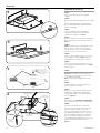
STEP 3:
Install the (4) T-Bar clips included with the
luminaire (located in pre-pack fastened to
luminaire junction box). See Figure 1.
STEP 4:
Place the CR-B troffer into the T-Bar Ceiling panel.
Ensure T-Bar clips are attached to the T-Bar. See
Figure 2.
STEP 5:
NOTE: For GTD luminaires skip to SETUP section.
Drill 2.5” hole in ceiling at desired location of
test switch. Make sure test switch conduit from
luminaire will reach chosen location.
STEP 6:
Insert test switch adapter into hole. Orient test
switch adapter as shown in Figure 3 and secure
with provided 2.5” nut until tight to ceiling tile.
STEP 7:
Fasten test switch from the luminaire to the test
switch adapter using provided ¾” nut. See Figure
3 for orientation.
SETUP
OPTION: Power whip (if installed) skip Steps 1-3
and refer directly to the Electrical Connections
section and wire flying leads.
Note: Power whip is not supported for -GTD
options.
STEP 1:
Disconnect power to circuit by turning circuit
breaker OFF before installation.
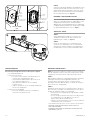
STEP 2:
Remove the cover of the power supply junction
box and bring conduit into the power supply
compartment using one of the provided knock-
outs. See Figure 4.
STEP 3:
Wire luminaire per ELECTRICAL CONNECTIONS
section and push all leads into the junction boxes.
STEP 4:
Luminaires ordered with SC1 are provided
with factory installed integrated Cree Lighting
SmartCast® Wireless fixture control with
occupancy and Daylight sensor. Make sure the
blue LED has a two-blink sequence. If not, please
proceed to Troubleshooting section. Otherwise
proceed to commissioning as per SmartCast®
Technology Deployment guide. Please refer to the
SmartCast® documentation for details. See
Figure 5.
1
2
4Access Plate to Power
Supply Compartment
Power Supply
Compartment
EB Activation
Junction Box Cover
3
2.5” Nut
Test Switch
Adapter
Ceiling
Test Switch From
Luminaire
3/4” Nut
Optional Power
Whip
(if installed)

3 of 5 LPN05500X0004A0_A
TROUBLESHOOTING:
Out of the box, if the light does not turn on when power is applied:
• Check Wiring with power off
• If wired correctly for SC1:
• Check to see if blue LED has a two-blink sequence. If
not, please proceed to RESET procedure.
• If you have done a RESET, and the light is still off, call
Cree Lighting Customer Service.
• If blue LED is on solid or off, call Cree Lighting
Customer Service.
• If light is unresponsive, use Cree Lighting Configuration
Tool to verify configuration.
• If wired correctly for VD0/VRF:
• Refer to the installation instructions included with
Lutron Vive or at www.lutron.com.
EMERGENCY DRIVER CHECK
NOTE: For short-term testing of the emergency function, the battery
must be charged for at least one hour. The emergency driver must be
charged for at least 24 hours before conducting a long-term test.
STEP 1:
When AC power is applied, the charging indicator light is illuminated,
indicating the battery is being charged. When power fails, the
emergency driver automatically switches to emergency power,
operating the LED array. When AC power is restored, the emergency
driver returns to the charging mode.
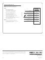
STEP 2:
Although no routine maintenance is required to keep the emergency
driver functional, it should be checked periodically to ensure that it is
working. The following schedule is recommended:
• Visually inspect the charging indicator light monthly. It should
be illuminated.
• Test the emergency operation of the fixture at 30-day intervals
for a minimum of 30 seconds. When the test switch is
depressed, the LED array should operate.
• Conduct a 90-minute discharge test once a year. The LED array
should operate for at least 90 minutes.
If the luminaire fails any of these checks, consult service personnel.
REFER ANY SERVICING INDICATED BY THESE CHECKS TO
QUALIFIED PERSONNEL
EMERGENCY DRIVER AND AC DRIVER MUST BE FED FROM THE
SAME BRANCH CIRCUIT
5
LUTRON VIVE SENSOR
(VDO/VRF)
Ambient Light Sensor /
Blue LED indicator
Motion
Sensor
Reset
Button
Ambient Light Sensor /
Blue LED indicator
Motion
Sensor
Reset
Button
SmartCast® SENSOR
(SC1)
STEP 7:
Luminaires ordered with VD0/VRF are provided with factory
installed Lutron Vive Wireless fixture control. For set-up
programming, troubleshooting with a Lutron Vive system,
please refer to the installation instructions included with
Vive or at www.lutron.com. See Figure 5.
EXPANDED JBOX ASSEMBLY OPTION:
In the case of through wiring with conductors larger than 14
gauge, it is recommended to utilize the EJBCR-5PK accessory
to expand the junction box volume, thereby allowing for
additional space for wiring and wiring fasteners. EJBCR-5PK
is supplied separately and attaches to existing J-Box assembly.
It is sold in minimum quantities of five. See Figure 6.
SMARTCAST® RESET
STEP 1:
Actuate RESET button through the access hole. Press
and hold Reset button until the blue LED flashes fast
(approximately 5 seconds). See Figure 5.
STEP 2:
Release the Reset button for 1 second (Fast flashing
continues). Press and hold Reset for 1 second until fast
flashing stops. If the blue LED does not respond with the
two-blink sequence, please repeat the RESET procedure.
6

4 of 5 LPN05500X0004A0_A
FCC NOTICE
CAUTION: Changes or modifications not expressly approved could void
your authority to use this equipment.
This device complies with Part 15 of the FCC Rules. Operation to
the following two conditions: (1) This device may not cause harmful
interference, and (2) this device must accept any interference received,
including interference that may cause undesired operation.
The LED in the front of this device operates within Risk Group 1 levels
per IEC 62471.
This device has been tested and found to comply with the limits for
a Class A digital device, pursuant to Part 15 of the FCC Rules. These
limits are designed to provide reasonable protection against harmful
interference when the device is operated in a commercial environment.
This device generates, uses, and can radiate radio frequency energy
and, if not installed and used in accordance with the instruction manual,
may cause harmful interference to radio communications. Operation of
this device in a residential area is likely to cause harmful interference
in which case the user will be required to correct the interference at his
own expense.
INDUSTRY CANADA STATEMENT
This device complies with Industry Canada licence-exempt RSS
standard(s). Operation is subject to the following two conditions: (1) this
device may not cause interference, and (2) this device must accept any
interference, including interference that may cause undesired operation
of the device. In addition, this device complies with ICES-003 of the
Industry Canada (IC) Regulations.
Le présent appareil est conforme aux CNR d’Industrie Canada
applicables aux appareils radio exempts de licence. L’exploitation est
autorisée aux deux conditions suivantes : (1) l’appareil ne doit pas
produire de brouillage, et (2) l’utilisateur de l’appareil doit accepter tout
brouillage radioélectrique subi, même si le brouillage est susceptible
d’en compromettre le fonctionnement.
RF EXPOSURE NOTICE:
To comply with the FCC/IC RF exposure compliance requirements,
this device and its antenna must not be co-located or operating to
conjunction with any other antenna or transmitter.
This equipment shall be installed and operated with minimum distance
5 cm between the radiator & your body. No other antenna is authorized
for use with this product.
Pour correspond aux requis d’exposition au FCC/IC RF, cet appareil et
son antenne ne doivent etre localisee tout pret ou operer en conjunction
ave d’autres antennes ou transmetteurs. Cet equipement doit etre
installe et opere avec une distance minimum 5 cm entre l’emetteur et
votre corps. Aucune autre antenne externe n’est autorisee a etre utilise
avec ce produit.
ELECTRICAL CONNECTIONS- EB
NOTE: The emergency driver must be fed
from the same branch as the AC Driver.
STEP 1:
Make the following electrical connections:
In Power Supply Junction Box:
a. Connect the black luminaire lead to
the switched line or Hot 1.
b. Connect the yellow/black luminaire lead
to the unswitched supply or Hot 1.
c. Connect white luminaire lead to the neutral or Hot 2.
d. Connect ground bare or green/yellow
wire lead to the supply ground lead.
STEP 2:
a. Reattach junction box lid over power wire
connections. Make sure no wires are pinched.
b. Supply AC power to luminaire.
STEP 3:
a. Remove EB activation junction box cover. See
Figure 4.
b. Locate the (2) black/white leads in junction box and
connect them.
c. Replace EB activation junction box cover. Make sure no
wires are pinched.
SUPPLY WIRING
POWER SUPPLY
JUNCTION BOX
GROUND GREEN/YELLOW
YELLOW/BLACK
SWITCHED HOT 1 BLACK
UNSWITCHED HOT 1
WHITE
NEUTRAL
OR HOT 2
** NOTE: DO NOT mate leads until installation
is complete and AC power is supplied
**BLACK/WHITE
**BLACK/WHITE
ENABLE
LEADS
LUMINAIRE EB
ACTIVATION
JUNCTION BOX
* NOTE: For Power Whip options
*RED

5 of 5 LPN05500X0004A0_A
www.creelighting.com
© 2023 Cree Lighting, A company of IDEAL INDUSTRIES. All rights reserved. For informational purposes only. Content
is subject to change. See www.creelighting.com/warranty for warranty and specifications. Cree® and the Cree Lighting
logo are registered trademarks of Cree, Inc. SmartCast® is a registered trademark, and CR14™, CR22™ and CR24™ are
trademarks of Cree Lighting, A company of IDEAL INDUSTRIES.
ELECTRICAL CONNECTIONS- GTD
NOTE: GTDU is internally wired as Branch Circuit
Emergency Lighting Transfer Switch (BCELTS).
STEP 1:
In Power Supply Junction Box:
a. Connect the black luminaire lead to the
unswitched line or unswitched Hot 1.
b. Connect the red luminaire lead to the
switched line or switched Hot 1.
c. Connect the white luminaire lead to the
normal panel neutral or Hot 2.
d. Connect the green or green/yellow ground
lead to the supply ground lead.
e. Connect blue luminaire lead to the emergency Hot.
f. Connect blue/white luminaire lead
to the emergency neutral.
STEP 2:
a. Reattach junction box lid over power wire
connections. Make sure no wires are pinched.
b. Supply AC power to luminaire.
NORMAL PANEL NEUTRAL
OR HOT 2
SUPPLY WIRING
GROUND
WHITE
GREEN/YELLOW
POWER WIRING
JUNCTION BOX
BLACK
SWITCHED HOT 1 RED
UNSWITCHED HOT 1
EMERGENCY HOT BLUE
EMERGENCY NEUTRAL BLUE/WHITE
-
 1
1
-
 2
2
-
 3
3
-
 4
4
-
 5
5


