Installation and Operation Instructions
Devonshire™ Direct-Vent Gas Fireplace
Models
Devonshire36TEN Devonshire36TEP
Devonshire42TEN Devonshire42TEP
P/N 126730-01 Rev. H 01/2019
Report No. F09 -099
PFS
®
USC
P126730-01
INSTALLER: Leave this manual with the appliance.
CONSUMER: Retain this manual for future reference.
Installateur : Laissez cette notice avec l’appareil.
Consommateur : Conservez cette notice pour
consultation ultérieure.
This appliance may be installed in an aftermarket permanently located, manufactured home (USA only) or
mobile home, where not prohibited by local codes. This appliance is only for use with the type of gas indicated
on the rating plate. This appliance is not convertible for use with other gases, unless a certified kit is used.
Cet appareil peut installé dans une maison préfabriquée (mobile) déjà installée à demeure, si les réglements
locaux le permettent. Ce appareil doit être utilisé uniquement avec le type de gaz indiqué sure la plaque
signalétique. Cet appareil ne peut être converti à d’autres gaz, sauf si une trousse de conversion est utilsée.
WARNING:
FIRE OR EXPLOSION HAZARD
Failure to follow safety warnings exactly could
result in serious injury, death, or property
damage.
AVERTISSEMENT
RISQUED’INDENDIE OU D’EXPLOSION
Le non-respect Des avertissements de sécurité pourrait
d’entraîner des blessures graves, la mort ou des dom-
mages matériels.
— Do not store or use gasoline or other flammable
vapors and liquids in the vicinity of this or any
other appliance.
— WHAT TO DO IF YOU SMELL GAS
• Do not try to light any appliance.
• Do not touch any electrical switch; do not use
any phone in your building.
• Leave the building immediately.
• Immediately call your gas supplier from a
neighbor’s phone. Follow the gas supplier’s
instructions.
• If you cannot reach your gas supplier, call the
fire department.
— Installation and service must be performed by
a qualified installer, service agency or the gas
supplier.
— Ne pas entreposer ni utilizer d’essence ni d’autres
vapeurs ou liquides inflammables dans le voisinage de
cet appareil ou de tout autre appareil.
— QUE FAIRE SI VOUS SENTEZ UNE ODEUR DE GAZ:
• Ne pas tenter d’allumer d’appareil.
• Ne touchez à aucan interrupteur. Ne pas vous servir des
téléphones se trouvant dans le bâtiment où vous trouvez.
• Sortez immédiatement de bâtiment.
• Appelez immédiatement votre fournisseur de gaz depuis
un voisin. Suivez les instructions du fournisseur.
• Si vous ne pouvez rejoindre le fournisseur de gaz, appelez
le service des incindies.
— L’installation et l’entretien doivent être assurés par un
installateur ou un service d’entretien qualifié ou par le
fournisseur de gaz.
Ce manuel est disponible en francais, simplement
en faire la demande. Numéro de la pièce 126730-02

Astria.us.com 126730-01H2
DANGER
HOT GLASS WILL
CAUSE BURNS.
DO NOT TOUCH GLASS
UNTIL COOLED.
NEVER ALLOW CHILDREN
TO TOUCH GLASS.
A barrier designed to reduce the risk of burns from the hot viewing glass is pro-
vided with this appliance and shall be installed for the protection of children and
other at-risk individuals.
DANGER
PELIGRO
VITRE CHAUDE
RISQUE DE BRÛLURES.
NE TOUCHEZ PAS UNE VITRE
NON REFROIDIE.
NE LAISSEZ JAMAIS UN ENFANT
DE TOUCHER LA VITRE.
EL VIDRIO CALIENTE
CAUSARÁ QUEMADURAS.
USTED DEBE NUNCA
TOCAR EL VIDRIO CALIENTE.
LOS NIÑOS DEBEN NUNCA
TOCAR EL VIDRIO.
L’écran pare-étincelles fourni avec ce foyer réduit le risque de brûlure en cas de
contact accidentel avec la vitre chaude et doit être installé pour la protection Des
enfants et Des personnes à risques.
Vea el volante adjunto para la representación de color adecuado
See attached color flyer for proper color representation
Voir ci-joint tract pour une bonne représentation de la couleur
Se provee con este aparato una barrera de protección (malla), diseñada para reducir
el riesgo de quemaduras por contacto accidental con el vidrio caliente que debe estar
instalada para protección de infantes y otros individuos en riesgo.
SAFETY AND YOUR FIREPLACE

Astria.us.com126730-01H 3
Afin d’éviter les brûlures
graves ou les blessures,
ne pas retirer l’écran de
protection de la foyer qui
empêche tout contact
direct avec la vitre.
Para evitar quemaduras y lesiones
graves, no quite el protector de malla
o guardia de seguridad que evita el
contacto directo con el vidrio.
Seguridad y su
chimenea
La sécurité et
votre foyer
[FRENCH][ENGLISH] [SPANISH]
Safety and Your
Fireplace
To prevent severe burns
and injuries, do Not remove
the barrier on the appliance
which prevents direct
contact with the glass.
All parts of your
IHP fireplace get
EXTREMELY HOT!
Toutes les parties de votre
foyer IHP deviennent
EXTRÊMEMENT CHAUDES !
¡Todas las partes de la
chimenea IHP se ponen
MUY CALIENTES!
Follow the safety instructions
below and be sure everyone in your
household understands this burn
hazard:
• The surfaces on your fireplace get
EXTREMELY HOT!
• The glass on the front of the
fireplace reaches EXTREMELY HIGH
temperatures and can cause severe
burns if touched.
• Keep children away from an
operating fireplace. Closely
supervise children in any room
where a fireplace is operating to
prevent contact with glass.
• Keep clothing, furniture, gasoline,
and other flammable liquids away
from the fireplace.
• Even after the gas is turned
off, fireplace surfaces remain
extremely hot.
Be sure to attach the enclosed Safety-
in-Operation Warnings where you
turn on your fireplace, to help remind
everyone of the dangers associated
with high temperatures
(Page 26)
.
Read Important Safety Information
(Page 4)
.
Suivez les instructions de sécurité
ci-dessous et veillez à ce que tous
les membres de votre famille soient
conscients du danger de brûlure
encouru :
• Les surfaces de votre foyer
deviennent EXTRÊMEMENT CHAUDES
!
• La vitre située à l'avant du
foyer atteint des températures
EXTRÊMEMENT ÉLEVÉES et peut
causer de graves blessures en cas de
contact.
• Tenez les enfants à l'écart du foyer
lorsqu'il fonctionne. Surveillez
attentivement les enfants dans les
pièces où un foyer est utilisé afin
d'éviter qu'ils ne soient en contact
avec la vitre.
• Tenez tous les vêtements, les
meubles, l'essence et tout autre
liquide inflammable à l'écart du foyer.
• Même après fermeture du gaz, les
surfaces du foyer restent extrêmement
chaudes.
Veillez à coller les Étiquettes de mise
en garde relatives à la sécurité
d'utilisation à l'endroit où vous
utilisez le foyer, pour rappeler à tous
les utilisateurs les dangers liés aux
températures élevées
(Page 26)
.
Lisez L’information de sûreté
importante (Page 4)
.
Siga las instrucciones de seguridad
a continuación y asegúrese de que
todos en su hogar sepan acerca de
este peligro de quemadura:
• ¡Las superficies de la chimenea se
ponen MUY CALIENTES!
• El vidrio delante de la
chimenea alcanza temperaturas
EXTREMADAMENTE ALTAS y puede
causar quemaduras graves si se toca.
• Mantenga a los niños alejados de
la chimenea en funcionamiento.
Supervise en forma cercana a los
niños en cualquier cuarto donde
haya una chimenea funcionando para
impedir el contacto con el vidrio.
• Mantenga la ropa, mobiliario,
gasolina y otros líquidos inflamables
alejados de la chimenea.
• Aún después de haber apagado el
gas, las superficies de la chimenea
permanecen extremadamente calientes.
Asegúrese de colocar las Etiquetas
de advertencia de seguridad de
operación en el lugar donde enciende
la chimenea, para que todos recuerden
los peligros asociados con las altas
temperaturas
(Página 26)
.
Lea Información importante de
seguridad (página 4).

Astria.us.com 126730-01H4
Important Safety Informa-
tion
1. WARNING: Do not operate appliance
with the glass front removed, cracked,
or broken.
2. Do not use this appliance if any part
has been under water. Immediately
call a qualified service technician to
inspect the appliance and to replace
any part of the control system and
any gas control which has been under
water.
3. Due to high temperatures, the appli-
ance should be located out of traffic
and away from furniture and draperies.
4. Children and adults should be alerted
to the hazards of high surface tem-
perature and should stay away to avoid
burns or clothing ignition.
5. Clothing or other flammable material
should not be placed on or near the
appliance.
6. Young children should be carefully
supervised when they are in the same
room as the appliance. Toddlers,
young children, and others may be sus-
ceptible to accidental contact burns.
A physical barrier is recommended
if there are at-risk individuals in the
house. To restrict access to a fireplace
or stove, install an adjustable safety
gate to keep toddlers, young children,
and other at-risk individuals out of the
room and away from hot surfaces.
7. Any safety screen, guard or barrier
removed for servicing an appliance
must be replaced prior to operating
the appliance.
8. Installation and repair should be done
by a qualified service person. The
appliance should be inspected before
use and at least annually by a profes-
sional service person. More frequent
cleaning may be required due to
excessive lint from carpeting, bedding
material, et cetera. It is imperative
that control compartments, burners,
and circulating air passageways of the
appliance be kept clean. See mainte-
nance instructions on Page 28.
L’information de sûreté
importante
1. AVERTISSEMENT. Ne pas utiliser l’appareil
si le panneau frontal en verre n’est pas en
place, est craqué ou brisé.
2. Ne pas se servir de cet appareil s’il a été
plongé dans l’eau, même partiellement.
Faire inspecter l'appareil par un technicien
qualifié et remplacer toute partie du systéme
de contrôle et toute commande qui ont été
plongées dans l'eau.
3. En raison des températures élevées,
l’appareil devrait être installé dans un
endroit où il y a peu de circulation et loin
du mobilier et des tentures.
4. Les enfants et les adultes devraient être
informés des dangers que posent les tem-
pératures de surface élevées et se tenir à
distance afin d’éviter des brûlures ou que
leurs vêtements ne s’enflamment.
5. On ne devrait pas placer de vêtements
ni d’autres matières inflammables sur
l’appareil ni à proximité.
6. Les jeunes enfants devraient être surveillés
étroitement lorsqu’ils se trouvent dans la
même pièce que l’appareil. Les tout petits,
les jeunes enfants ou les adultes peuvent
subir des brûlures s’ils viennent en contact
avec la surface chaude. Il est recommandé
d’installer une barrière physique si des
personnes à risques habitent la maison.
Pour empêcher l’accès à un foyer ou à un
poêle, installez une barrière de sécurité
; cette mesure empêchera les tout petits,
les jeunes enfants et toute autre personne
à risque d’avoir accès à la pièce et aux
surfaces chaudes.
7. Tout écran ou protecteur retiré pour per-
mettre l’entretien de l’appareil doit être
remis en place avant de mettre l’appareil
en marche.
8. L’installation et la réparation devrait être
confiées à un technicien qualifié. L’appareil
devrait faire l’objet d’une inspection par un
technicien professionnel avant d’être utilisé
et au moins une fois l’an par la suite. Des
nettoyages plus fréquents peuvent être
nécessaires si les tapis, la literie, et cetera
produisent une quantité importante de pous-
sière. Il est essentiel que les compartiments
abritant les commandes, les brûleurs et les
conduits de circulation d’air de l’appareil
soient tenus propres. Voyez les instructions
d’entretien à la Page 28.
Información importante de
seguridad
1. ADVERTENCIA: No opere el artefacto con el
frente de vidrio quitado, agrietado o roto.
2. No use este artefacto si alguna de sus partes
ha estado bajo agua. Llame de inmediato
a un técnico de servicio calificado para
que inspeccione el artefacto y reemplace
cualquier parte del sistema de control y
cualquier control de gas que haya estado
bajo agua.
3. Debido a las altas temperaturas, el artefacto
debe situarse fuera de las áreas de tráfico y
lejos del mobiliario y cortinas.
4. Se debe alertar a los niños y adultos sobre
los peligros de las altas temperaturas en la
superficie y que se mantengan alejados para
evitar quemaduras o ignición de la ropa.
5. No debe colocarse ropa u otros materiales
inflamables sobre y cerca del artefacto.
6. Se debe supervisar de cerca a los niños
cuando estén en el mismo cuarto que el
artefacto. Los niños pequeños, los jóvenes
y otras personas pueden ser susceptibles
a quemaduras por contacto accidental. Se
recomienda instalar una barrera física si hay
personas en riesgo en la casa. Para restringir
el acceso a una chimenea o estufa, instale
una puerta de seguridad ajustable para
mantener a los niños pequeños, jóvenes y
otras personas en riesgo fuera del cuarto y
lejos de las superficies calientes.
7. Cualquier malla o resguardo de seguridad
quitado para dar servicio a un artefacto, debe
reinstalarse antes de operar el artefacto.
8. Una persona de servicio competente debe
realizar la instalación y reparación. Una
persona de servicio profesional debe
inspeccionar el artefacto antes de usar al
menos una vez por año. Se puede requerir
limpieza más frecuente debido a la pelusa
excesiva del alfombrado, del material de
cobijas, etc. Es imprescindible mantener
limpios los compartimientos de control, los
quemadores y los pasajes de circulación del
aire del artefacto. Ver las instrucciones de
mantenimiento en la página 28.
IMPORTANT SAFETY INFORMATION

Astria.us.com126730-01H 5
SAFETY
WARNING: Improper installation, adjustment,
alteration, service or maintenance can cause injury
or property damage. Refer to this manual for correct
installation and operational procedures. For assis-
tance or additional information consult a qualified
installer, service agency or the gas supplier.
This appliance is only for use with the type of gas
indicated on the rating plate. This appliance is not
convertible for use with other gases, unless a certi-
fied kit is used.
WARNING: This product can expose you to chemicals
including Carbon Black, which is known to the State of
California to cause cancer, and Carbon Monoxide, which
is known to the State of California to cause birth defects
or other reproductive harm. For more information go to
www.P65Warnings.ca.gov
AVERTISSEMENT: Ce produit peut vous exposer
à des produits chimiques, y compris du carbone noir
qui est reconnu par l'État de Californie comme un
produit cancérigène, et du monoxyde de carbone, qui
est reconnu par l'État de Californie comme pouvant
causer des déformations fœtales ou perturber la fonc-
tion reproductive. Pour plus d’information, aller sur
www.P65Warnings.ca.gov
Safety and your fireplace .............................................................. 2
Important Safety Information ........................................................ 4
Safety ........................................................................................... 5
Local Codes .................................................................................. 7
Product Identification .................................................................... 7
Product Features ........................................................................... 8
Requirements for the Commonwealth of Massachusetts.............. 8
Pre-installation .............................................................................. 8
Location of Termination Cap ....................................................... 11
Venting Installation ..................................................................... 12
Fireplace Installation ................................................................... 17
Installer - Attaching Safety In Operation Warnings ......................22
Operation ................................................................................... 23
Thank you for your purchase. We appreciate your
business!
Please carefully read and follow all instructions in this manual. Pay
special attention to all warnings and safety information.
Following these safety, care, and operation instructions will help
ensure many years of dependable and enjoyable service from your
fireplace.
Please read and understand these instructions before installing
or operating.
TABLE OF CONTENTS
Gas Control Module System ........................................................25
Homeowner's - Attaching Safety In Operation Warnings ..............26
Inspecting Burners ....................................................................... 27
Cleaning and Maintenance ...........................................................28
Troubleshooting ...........................................................................29
Specifications ...............................................................................31
Wiring Diagram ............................................................................31
Parts ............................................................................................32
Technical Service .........................................................................37
Replacement Parts .......................................................................37
Service Hints ................................................................................ 37
Accessories .................................................................................. 38
Warranty ......................................................................................39
State of Massachusetts: The installation must be
made by a licensed plumber or gas fitter in the Com-
monwealth of Massachusetts.
IMPORTANT: Read this owner’s manual carefully and
completely before trying to assemble, operate or ser-
vice this fireplace. Improper use of this fireplace can
cause serious injury or death from burns, fire, explo-
sion, electrical shock and carbon monoxide poisoning.
DANGER: Carbon monoxide poisoning may lead
to death!
WARNING: Do not slam or strike glass doors.
Damage can result in a hazardous condition.
This vented gas fireplace is a sealed combustion gas fireplace de-
signed for residential applications. This fireplace must be installed
with INNOVATIVE HEARTH PRODUCTS (IHP) vent pipe components
and terminations.
NOTICE: Decorative product not for use as a heating
appliance.
This fireplace must be installed by a qualified (certified or licensed)
service person. It brings in fresh air for combustion through the outer
pipe and combustion gases are exhausted through the inner pipe. If
the glass door assembly and venting pipe are not properly seated,
connected and sealed, carbon monoxide leakage (spillage) can occur.

Astria.us.com 126730-01H6
Carbon Monoxide Poisoning: Early signs of carbon monoxide poison-
ing resemble the flu, with headaches, dizziness or nausea. If you have
these signs, the fireplace may not be working properly. Get fresh air
at once! Have fireplace serviced. Some people are more affected by
carbon monoxide than others. These include pregnant women, people
with heart or lung disease or anemia, those under the influence of
alcohol and those at high altitudes.
Natural and Propane/LP Gas: Natural and propane/LP gas are odor-
less. An odor-making agent is added to the gas. The odor helps you
detect a gas leak. However, the odor added to the gas can fade. Gas
may be present even though no odor exists.
Make certain you read and understand all warnings. Keep this manual
for reference. It is your guide to safe and proper operation of this
fireplace.
WARNING: Any change to this fireplace or its con-
trols can be dangerous. Do not modify this fireplace
under any circumstances. Any parts removed for ser-
vicing must be replaced prior to operating fireplace.
WARNING: Do not use a blower insert, heat ex-
changer insert or other accessory not approved for use
with this fireplace.
WARNING: This appliance is only for use with
the type of gas indicated on the rating plate. This
appliance is not convertible for use with other gases
unless a certified kit is used.
WARNING: Do not allow fans to blow directly into
the fireplace. Avoid any drafts that alter burner flame
patterns.
Due to high temperatures, the appliance should be
located out of traffic and away from furniture and
draperies.
Clothing or other flammable material should not be
placed on or near the appliance.
Do not use this fireplace to cook food or burn paper
or other flammable material.
Any safety screen, guard, or barrier removed for
servicing an appliance must be replaced prior to
operating the appliance.
DO NOT ATTEMPT TO ALTER OR MODIFY THE CON-
STRUCTION OF THE APPLIANCE OR ITS COMPO-
NENTS. ANY MODIFICATION OR ALTERATION MAY
VOID THE WARRANTY, CERTIFICATION AND LISTINGS
OF THIS UNIT.
SAFETY Continued
Installation and repair should be done by a qualified
service person. The appliance should be inspected
before use and at least annually by a professional
service person. More frequent cleaning may be re-
quired due to excessive lint from carpeting, bedding
material, etcetera. It is imperative that control com-
partments, burners, and circulating air passageways
of the appliance be kept clean.
Children and adults should be alerted to the hazards
of high surface temperature and should stay away
to avoid burns or clothing ignition.
A barrier designed to reduce the risk of burns from
the hot viewing glass is provided with this appliance
and shall be installed for the protection of children
and other at-risk individuals.
If the barrier becomes damaged, the barrier shall
be replaced with the manufacturer's barrier for this
appliance.
Keep the area around your fireplace clear of combus-
tible materials, gasoline and other flammable vapor
or liquids. Do not run fireplace where these are used
or stored.
1. For propane/LP fireplace, do not place propane/LP supply tank(s)
inside any structure. Locate propane/LP supply tank(s) outdoors.
To prevent performance problems, do not use propane/LP fuel
tank of less than 100 lb. capacity.
2. If you smell gas
• shut off gas supply
• do not try to light any appliance
• do not touch any electrical switch; do not use any phone in your
building
• leave the building immediately
• immediately call your gas supplier from a neighbor’s phone.
Follow the gas supplier's instructions
• if you cannot reach your gas supplier, call the fire department.
3. Never install the fireplace
• in a recreational vehicle
• in windy or drafty areas where curtains or other combustible (flam-
mable) objects can make contact with the fireplace front
• in high traffic areas
4. Turn fireplace off and let cool before servicing, installing or
repairing. Only a qualified service person should install, service
or repair this fireplace. Have fireplace inspected annually by a
qualified service person.
5. You must keep control compartments, burners and circulating
air passages clean. More frequent cleaning may be needed due
to excessive lint and dust from carpeting, bedding material, etc.
Turn off the gas valve and pilot light before cleaning fireplace.

Astria.us.com126730-01H 7
SAFETY Continued
6. Have venting system inspected annually by a qualified service
person. If needed, have venting system cleaned or repaired. See
Cleaning and Maintenance, Page 28.
7. Do not use any solid fuels (wood, coal, paper, cardboard, etc.)
in this fireplace. Use only the gas type indicated on fireplace
nameplate.
8. This appliance, when installed, must be electrically grounded in
accordance with local codes or, in the absence of local codes, with
the National Electrical Code, ANSI/NFPA 70 or Canadian Electrical
Code, CSA C22.1.
9. Do not use fireplace if any part has been exposed to or under
water. Immediately call a qualified service person to arrange for
replacement of the unit.
10. Do not operate fireplace if any log is broken.
11. Do not operate fireplace with glass door removed, cracked or
broken.
12. Provide adequate clearances around air openings.
LOCAL CODES
Install and use fireplace with care. Follow all local codes. In the
absence to local codes, use the current National Fuel Gas Code ANSI
Z223.1/NFPA 54* (USA) or the current CAN/CGA B149.1 Installation
Code (Canada).
*Available from:
American National Standards Institute, Inc.
25 West 43rd Street, 4th floor
New York, NY 10036
National Fire Protection Association, Inc.
1 Batterymarch Park
Quincy, MA 02169-7471
Listing: This fireplace complies with the National Safety Standards
and is listed and tested by the PFS Corporation to ANSI Z21.50/CSA
2.22 standard as a vented gas fireplace.
These appliances comply with CSA P.4.1-2015 “Testing Method for
Measuring Annual Fireplace Efficiency. P4 (EnerGuide) is a measure-
ment of the Canadian Office of Energy Efficiency.
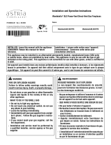
PRODUCT IDENTIFICATION
Figure 1 - Direct Vent Fireplace
Outer Glass
Door
Screen
Barrier
J7450 36"
J7456 42"
Log Set
Flue Collar Top Spacer
Spacer
Nailing Flange
Lower Door/
Control Cover
Herringbone Brick
Refractories
Grate
Based on CSA P. 4.1-2015

Astria.us.com 126730-01H8
COMMONWEALTH OF MASSACHUSETTS REQUIREMENTS
These appliances are approved for installation in the US state of
Massachusetts if the following additional requirements are met:
• Install this appliance in accordance with Massachusetts Rules
and Regulations 248 C.M.R. Sections 4.00 through 8.00.
• Installation and repair must be done by a plumber or gas fitter
licensed in the Commonwealth of Massachusetts.
• The flexible gas line connector used shall not exceed 36 inches
(92 centimeters) in length.
• The individual manual shut-off must be a T-handle type valve.
REQUIREMENTS FOR THE COMMONWEALTH OF MASSACHUSETTS
Massachusetts Horizontal Vent Requirements
In the Commonwealth of Massachusetts, horizontal terminations
installed less than seven (7) feet above the finished grade must
comply with the following additional requirements:
• A hard wired carbon monoxide detector with an alarm and
battery back-up must be installed on the floor level where
the gas fireplace is installed. The carbon monoxide detector
must comply with NFPA 720, be ANSI/UL 2034 listed and be
ISA certified.
• A metal or plastic identification plate must be permanently
mounted to the exterior of the building at a minimum height
of eight (8) feet above grade and be directly in line with the
horizontal termination. The sign must read, in print size no less
than one-half (1/2) inch in size, GAS VENT DIRECTLY BELOW.
KEEP CLEAR OF ALL OBSTRUCTIONS.
PRE-INSTALLATION
LOCATION AND SPACE REQUIREMENTS
Determine the safest and most efficient location for your direct vent
fireplace. Make sure that rafters and wall studs are not in the way of
the venting system. Choose a location where the heat output is not
affected by drafts, air conditioning ducts, windows or doors. Figure
2 shows some common locations. Be aware of all restrictions and
precautions before deciding the exact location for your fireplace and
termination cap.
When deciding the location of your fireplace, follow these rules:
• Do not connect this fireplace venting to a chimney flue serving a
separate solid-fuel burning fireplace or appliance.
• Due to high temperatures, do not locate this fireplace in high traffic
areas, windy or drafty areas or near furniture or draperies.
• Proper clearances must be maintained.
• If your fireplace is to be installed directly on carpeting, vinyl tile or any
combustible material other than wood, it must be installed on a metal
or wood panel extending the full width and depth of the fireplace (see
Figure 3).
• Your fireplace is designed to be used in zero clearance installations.
Wall or framing material can be placed directly against any exterior
surface on back, sides or top of your fireplace, except where standoff
spacers are integrally attached. If standoff spacers are attached to your
fireplace, these spacers can be placed directly against wall or framing
material. See framing details, Page 10.
• When locating termination cap, it is important to observe the
minimum clearances shown in Figure 8, Page 11.
• If recessing into a wall, you can avoid extra framing by positioning
your fireplace against an already existing framing member. Figure 2 - Common Fireplace Locations
Flush with a wall
Through exterior wall enclosed
in a chase
Corner
installation
• Do not recess termination cap into a wall or siding.
• You may paint the termination cap with 450º F (232º C) heat-
resistant paint to coordinate with the exterior finish.
• There must not be any obstruction such as bushes, garden sheds,
fences, decks or utility buildings within 24" from the front of the
termination cap and the front of outside air vent.
• Do not locate termination cap and outside air vent where excessive
snow or ice build up may occur. Be sure to clear vent termination
area after snow falls to prevent accidental blockage of venting sys-
tem. When using snow blowers, do not direct snow towards vent
termination area.
PRODUCT FEATURES
These are a few facts that can help you understand and enjoy your
direct vent fireplace:
• The venting system may be routed to the outside of your home in
several ways. It may vent through the roof (vertical) or it may vent
to an outside/exterior wall (horizontal). The vent pipe installation is
very important to allow for proper operation. You must follow the
venting instructions very carefully for either vertical or horizontal
applications.
• This fireplace may be installed in any room of your house provided
all local codes and these installation instructions are followed.
• Each time you turn on your fireplace, you may notice some amount
of condensation on the inside of the fireplace glass. This is normal
and will disappear after 10-20 minutes of operation.
• Your direct vent gas fireplace system (fireplace and venting) is a
balanced and sealed gas operating unit. It requires approximately
10-20 minutes of operating time before the flame pattern stabilizes.

Astria.us.com126730-01H 9
PRE-INSTALLATION Continued
Figure 3 - Fireplace Dimensions
Figure 4 - Electrical Outlet and Gas Knockout Locations
21 1/8" (537 mm) 36" Model
25 1/8" (638 mm) 42" Model
34 3/4" (883 mm) 42" Model
29 1/8" (740 mm) 36" Model
11 7/8" (302 mm) 36" Model
20 1/2" (521 mm) 36" Model
33 3/4" (857 mm)
42" Model
44" (1118 mm) 36" Model
35" (889 mm) 36" Model
42" (1067 mm) 42" Model
41" (1041 mm) 36" Model
48" (1219 mm) 42" Model
44" (1118 mm)
42" Model
40" (1016 mm)
36" Model
30" (762 mm)
36" Model
48" (1219 mm) 42" Model
24" (610 mm) 42" Model
13 5/8" (346 mm) 42" Model
Requires IHP 5" (127 mm) I.D.
8" (203 mm) O.D. Direct-Vent Pipe
2 1/4" (57 mm)
6 3/4" (171 mm)
10 3/4" (273 mm) 36" Model
11 1/2" (292 mm) 42" Model
2 1/4" (57 mm)
GAS LINE
KNOCK OUT
NAILING
FLANGE
NAILING
FLANGE
ELECTRICAL
OUTLET
LEFT SIDE RIGHT SIDE
GAS LINE
KNOCK OUT
10 3/4" (273 mm) 36" Model
11 1/2" (292 mm) 42" Model

Astria.us.com 126730-01H10
PRE-INSTALLATION Continued
CLEARANCES
Minimum clearances to combustibles for the fireplace are as follows:
*Back and sides 1" (26 mm)
Perpendicular walls 6" (153 mm)
Floor 0" (0 mm)
Ceiling to louver opening 42" (1067 mm)
Front 36" (915 mm)
Top of Standoffs 0" (0 mm)
Vent (See venting instructions for specific venting
clearances.)
Combustible material with a maximum thickness of 5/8" may be flush
with the top front of fireplace.
* For back and sides of fireplace, do not pack with insulation or other
materials. 1" clearance not required at nailing flanges.
NOTICE: This fireplace is intended for use as supple-
mental heat. Use this fireplace along with your primary
heating system. Do not install this fireplace as your
primary heat source. If you have a central heating
system, you may run system’s circulating blower
while using fireplace. This will help circulate the heat
throughout the house.
FRAMING AND FINISHING
Figures 5 and 5a shows typical framing of this fireplace. Figure 6 shows
framing for corner installation. All minimum clearances must be met.
If you are using a separate combustible mantel piece, refer to Figure 7
for proper installation height. You can install noncombustible mantels
at any height above the fireplace.
NOTE: Noncombustible mantels may discolor!
Ensure adequate accessibility clearances for servicing and proper
operation.
Figure 5 - Framing Clearances with Outside Air Flex Duct
Figure 6 - Framing Clearances for Corner Installation
Figure 7 - Clearances for Combustible Mantels
C
B
A
DE
FG
3
2
1
4
5
6
7
Wall
Ref. Mantel Depth Ref. Mantel from
Top of Opening
1 14" (356 mm) A 16" (406 mm)
2 12" (305 mm) B 14" (356 mm)
3 10" (254 mm) C 12" (305 mm)
4 8" (203 mm) D 10" (254 mm)
5 6" (152 mm) E 8" (203 mm)
6 4" (102 mm) F 6" (152 mm)
7 2" (51 mm) G 4" (102 mm)
36 3/8" (924 mm) 36" Model
15 3/4" (924 mm) 36" Model
51 3/8" (1305 mm)
36" Model
61 3/4" (1568 mm)
42" Model
19" (483 mm) 42" Model 41" (1041 mm) 36" Model,
48" (1219 mm) 42" Model
43" (1092 mm) 36" Model,
50" (1270 mm) 42" Model
Nailing
Flange
43 3/8" (1102 mm) 42" Model
Maintain 1" Clearance at Sides
and Back of Fireplace
44" (1118 mm) 36" Model
48" (1219 mm) 42" Model
48" (1219 mm) 42" Model
41" (1041 mm) 36" Model
Figure 5a - Framing Dimensions
22 1/8" (562 mm) 36" Model
41 1/2" (1054 mm) 36" Model
48 1/8" (1222 mm) 42" Model
26 1/8" (664 mm) 42" Model
44" (1118 mm)
36" Model
48" (1219 mm)
42" Model
NOTE: To avoid heat-related finish damage, we recommend the use
of high temperature paint (rated 175° F or higher) on the underside
of the mantel.
Minimum clearance requirements include any projections such as
shelves, window sills, mantels, etc. above the appliance.

Astria.us.com126730-01H 11
Fixed
Closed Openable Fixed
Closed
V
V
V
V
VV
V
V
X
X
VX
G
G
J
F
B
B
K
N
H
I
A
N
E
L
D
B
M
A
C
B
V
V
A
G
G
B
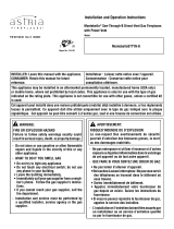
TERMINATION CAP AIR SUPPLY INLET GAS METER RESTRICTED AREA
(TERMINATION PROHIBITED)
A = clearance above grade, veranda, porch, deck, or
balcony [*12" (30.5 cm) minimum]
B = clearance to window or door that may be opened
[6" (15 cm) min. for 10,000 Btu or less; 9" (23 cm) in US
if between 10,000 and 50,000, 12" (30 cm) in Canada
if between 10,000 and 100,000; 12" (30 cm) in US if
greater than 50,000, 36" (91 cm) in Canada if greater
than 100,000]
C = clearance to permanently closed window
[minimum 12" (30.5 cm) recommended to prevent
condensation on window]
D = vertical clearance to ventilated soffit located above the
terminal within a horizontal distance of 24" (61 cm) from
the center-line of the terminal [18" (45.7 cm) minimum]
E = clearance to unventilated soffit [12" (30.5 cm) minimum]
F = clearance to outside corner (see below)
G = clearance to inside corner (see below)
H = *not to be installed above a meter/regulator assembly
within 36" (91.4 cm) horizontally from the center line
of the regulator
I = clearance to service regulator vent outlet [*72" (182.9 cm)
minimum]
J = clearance to non-mechanical air supply inlet to building
or the combustion air inlet to any other fireplace
[6" (15 cm) min. for 10,000 Btu or less; 9" (23 cm) in US
if between 10,000 and 50,000, 12" (30 cm) in Canada
if between 10,000 and 100,000; 12" (30 cm) in US if
greater than 50,000, 36" (91 cm) in Canada if greater
than 100,000]
K = clearance to a mechanical air supply inlet [*In Canada,
6 ft. (1.83m) minimum; In US 3 ft. (91 cm) above if within
10 ft. (3 m) horizontally]
L = † clearance above paved side-walk or a paved driveway
located on public property [*84" (213.3 cm) minimum]
M = clearance under veranda, porch, deck
[*12" (30.5 cm) minimum ‡]
N = clearance above a roof shall extend a minimum of
24" (61 cm) above the highest point when it passes
through the roof surface and any other obstruction within
a horizontal distance of 18" (45.7 cm)
† vent shall not terminate directly above a side-walk or paved driveway which is located between two
single family dwellings and serves both dwellings*
‡ only permitted if veranda, porch, deck or balconey is fully open on a minimum of 2 sides beneath the floor*
* as specified in CAN/CGA B149.1 Installation Codes (1991) for Canada and U.S.A.
Note: Local codes or regulations may require different clearances
A = 6" (15.2 cm)
Inside Corner
V
B
E
V
B = 6" (15.2 cm)
C = Maximum depth of 48" (121.9 cm)
for recessed location
D = Minimum width for back wall of
recessed location -
Combustible - 38" (965 mm)
Noncombustible - 24" (61 cm)
E = Clearance from corner in
recessed location-
Combustible - 6" (15.2 cm)
Noncombustible - 2" (5.1 cm)
Outside Corner Recessed Location
G
H
G = 12" (30.5 cm) minimum clearance
Balcony with No Side Wall
V
J
Combustible &
Noncombustible
H = 24" (61 cm)
J = 20" (50.8 cm)
Balcony with Perpendicular Side Wall
C
D
C
Termination Clearances for Buildings with Combustible and Noncombustible Exteriors
Openable
LOCATION OF TERMINATION CAP
Figure 8 - Minimum Clearances for Termination Cap

Astria.us.com 126730-01H12
VENTING INSTALLATION
NOTICE: Read these instructions completely before
attempting installation.
These models are tested and approved for use with an IHP (direct
vent) pipe components and terminations.
The venting system must terminate on the outside of the structure and
can not be attached to a chimney or flue system serving a separate
solid fuel or gas burning appliance. A direct vent appliance must
have its own venting system. DO NOT common vent this appliance.
These models are approved to be vented either horizontally through
an outside wall or vertically through a roof or chase enclosure using
the following guidelines:
• When venting system terminates horizontally on an outside wall,
you may install a standoff if the termination cap is to be installed
directly on a combustible finish such as vinyl, wood, stucco, etc.
• Never run the vent downward as this may cause excessive tem-
peratures which could cause a fire.
• Vent pipe air space clearances to combustibles are 1" on all sides
except on the horizontal sections, which requires 2" clearance
from the top of the pipe. Where the termination cap penetrates a
combustible wall, 1" air space clearance is required.
• Have fireplace and selected vent components on hand to help
determine the exact measurements when elbowing or offsetting.
Always use wall firestops when penetrating walls and firestops
when penetrating ceilings or attic spaces.
• For installation of fireplace at elevations of 4000 feet or greater,
pay special attention to venting requirement recommendations.
WARNING: Read all instructions completely and
thoroughly before attempting installation. Failure to
do so could result in serious injury, property damage
or loss of life.
NOTICE: Failure to follow these instructions will void the
warranty.
NOTICE: Do not seal termination cap to vent pipe. Cap
must be removable for vent inspection and mainte-
nance.
INSTALLATION PRECAUTIONS
• Wear gloves and safety glasses for protection
• Use extreme caution when using ladders or when on roof tops
• Be aware of electrical wiring locations in walls and ceilings
The following actions will void the warranty on your venting system:
• Installation of any damaged venting component
• Unauthorized modification of the venting system (Do not cut or alter
vent components)
• Installation of any component part not manufactured or approved
by IHP
• Installation other than as instructed by these instructions
WARNING: This gas fireplace and vent assembly
must be vented directly to the outside. The venting
system must NEVER be attached to a chimney serving
a separate solid fuel burning appliance. Each direct
vent gas appliance must use a separate vent system.
Do not use common vent systems.
WARNING: Vent pipe air space clearances to com-
bustibles are 1" on all sides except on the horizontal
sections, which require 2" clearances from the top
of the pipe. Where the termination cap penetrates a
combustible wall, 1" air space clearance is required.
INSTALLATION PLANNING
There are two basic types of direct vent installation:
• Horizontal Termination
• Vertical Termination
Horizontal Termination Installation
IMPORTANT: Horizontal square terminations require only inner por-
tion of wall firestop. Horizontal installations using round termination
require exterior portion of wall firestop.
1. Set fireplace in its desired location and determine the route your
horizontal venting will take. Do not secure fireplace until all venting
has been installed. Some installations require sliding fireplace in
and out of position to make final venting connections. Figures
15 and 16 on Pages 14 and 15, show different configurations
for venting with horizontal termination that will help you decide
which application best suits your installation. Check to see if wall
studs or roof rafters are in the path of your desired venting route.
If they are, you may want to adjust location of fireplace.
2. Direct vent pipe sections and components are designed with
special twist-lock connections.
Twist-Lock Procedure: Female ends of pipes have locking lugs
(indentations). These lugs will slide straight into matching slots
on male ends of adjacent pipes. Push pipe sections together and
twist one section clockwise approximately one-quarter turn until
sections are fully locked (see Figure 9, Page 13).
NOTE: Horizontal runs of vent must be supported every three feet.
Use wall straps for this purpose.
3. Assemble desired combination of pipe and elbows to fireplace flue
collar. If there are long portions of venting run, pre-assembled
pipe sections may be installed as subassemblies for convenience.
4. Carefully determine location where vent pipe assembly will pen-
etrate outside wall. Center of hole should line up with center line
of horizontal vent pipe. Mark wall for an 11-1/2" x 11-1/2" square
hole. Cut and frame square hole in exterior wall where vent will
be terminated. If wall being penetrated is constructed of noncom-
bustible material, such as masonry block or concrete, an 8-1/2"
hole with zero clearance is acceptable (see Figure 10 Page 13).
WARNING: Do not recess vent termination into any
wall. This will cause a fire hazard.

Astria.us.com126730-01H 13
VENTING INSTALLATION Continued
5. Noncombustible Exterior Wall: Position horizontal vent cap in
center of the 8-1/2" round hole and attach to exterior wall with
four wood screws provided. Before attaching vent cap to exterior
wall, run a bead of non-hardening mastic (pliable sealant) around
outside edges to make a seal between it and outside wall.
NOTE: Four wood screws provided should be replaced with ap-
propriate fasteners for stucco, brick, concrete or other types of
sidings (see Figure 11).
Combustible Exterior Wall: For stucco or wood exteriors, a sid-
ing standoff may be installed between vent cap and exterior wall.
Siding standoff is required if exterior wall is made of vinyl siding
material. Siding standoff prevents excessive heat from damaging
siding materials. Siding material must be cut to accommodate
standoff. Bolt vent cap to standoff. Apply non-hardening mastic
around outside edge of standoff. Position standoff/cap assembly
in the center of 11-1/2" square hole and attach to exterior wall with
provided wood screws (see Figure 12, Page 14). Siding standoff
must sit flush against exterior fascia material.
6. Connecting Vent Cap with Horizontal Vent Pipe: Slide wall firestop
over vent pipe before connecting horizontal run to vent cap (see
Figure 13, Page 14).
Carefully move fireplace, with vent assembly attached, toward wall
and insert vent pipe into horizontal termination. Pipe overlap should
be a minimum of 1-1/4" (see Figure 14, Page 14).
Slide wall firestop against interior wall surface and attach with
screws provided. See Figure 14, Page 14, for horizontal termina-
tion details.
Place fireplace into position and shim with noncombustible material
if needed. Nail or screw side flanges to framing to secure unit in
place.
IMPORTANT: Make sure fireplace is level before securing. If fire-
place is not level it will not work properly.
Figure 9 - Vent Pipe Connections
Figure 10 - Vent Opening Requirements Figure 11 - Installing Horizontal Vent Cap
(Noncombustible Exterior)
Female Locking
Lugs
Male Slots
Vent Opening
Combustible Wall
Vent Opening
Noncombustible Wall
(Framing Detail)
11
1
/
2
" (292 mm) Inside Framing
11
1
/
2
"
(292 mm)
8
1
/
2
"
(216 mm)
11
1
/
2
"
(292 mm)
Wood
Screw
Vent Cap
Apply Mastic
to All Four
Sides
Center of
Hole

Astria.us.com 126730-01H14
Vent Cap
(Horizontal
Termination)
Interior Wall
Surface
Wall
Firestop
Horizontal Vent Pipe
Screw
Figure 12 - Installing Siding Standoff (Combustible Exterior
Wall)
Figure 13 - Connecting Vent Cap with Horizontal Vent Pipe
Figure 14 - Typical Horizontal Termination Cap Mounting with
Additional Siding Standoff Installed Figure 15 - Horizontal Termination Using One 90° Elbow
Cut Siding Away to Fit
Standoff
Wood
Screw
Screws
Standoff
Vent
Cap
Apply Mastic
to All Four Sides
Siding Standoff
Screws
High Wind
Termination
Apply Mastic to
Outside Edge of
Standoff
Exterior Wall with
Vinyl Siding
11 1/2" (292 mm) x
11 1/2" (292 mm)
Framed Opening
Wall
Firestop
Direct
Vent
Pipe
VENTING INSTALLATION Continued
Horizontal Termination Configurations
Figure 15 shows a configuration for venting with horizontal termi-
nation with a chart of critical minimum and maximum dimensions
which MUST be met.
Figure 16, Page 15, shows a configuration for venting with horizontal
termination using two 90° elbows with a chart of critical minimum
and maximum dimensions which MUST be met.
If using a venting configuration of only horizontal venting with no
vertical run, a 1/4'' rise for every 12'' of run toward the termination
is required.
NOTICE: Do not seal termination cap to vent pipe. Cap
must be removable for vent inspection and mainte-
nance.
WARNING: Never run vent downward as this may
cause excessive temperatures which could cause a
fire. Operation of improperly installed and maintained
venting system could result in serious injury, property
damage or loss of life.
GROUND FLOOR INSTALLATION
Recommended Applications:
• Through the wall using round or square termination
• NOT FOR CORNER INSTALLATION
Wall Firestop H
90° Elbow
V + 90· Elbow
Horizontal High
Wind Square
Termination
(V) Vertical
Minimum Required
Vertical Pipe (H) Horizontal
Maximum
Inches (mm) feet (meters) feet (meters)
33" (838) 2 ft. (0.609) 7 ft. (2.134)
45" (1143) 3 ft. (0.914) 11 ft. (3.353)
57" (1448) 4 ft. (1.219) 20 ft. (6.096)
V + H = 40 feet (12.192 m) maximum
H = 20 feet (6.096 m) maximum
Minimum
Pipe Overlap
1 1/4" (32 mm)
Maintain 1" (26 mm)
Minimum Air Space
Around Outer Pipe
When Penetrating a
Wall
76" (1931 mm) Min. (42" Model)
73" (1855mm) Min. (36" Model)
1 ft (0.305 m)Pipe Min.
On Horizontal Run

Astria.us.com126730-01H 15
Figure 16 - Horizontal Termination Using Two 90° Elbows
VENTING INSTALLATION Continued
Vertical Termination Installation
NOTE: Vertical restrictor must be installed in all vertical installations.
1. Determine route your vertical venting will take. If ceiling joists,
roof rafters or other framing will obstruct venting system, consider
an offset (see Figure 17) to avoid cutting load bearing members.
NOTE: Pay special attention to these installation instructions for
required clearances (air space) to combustibles when passing
through ceilings, walls, roofs, enclosures, attic rafters, etc. Do not
pack air spaces with insulation. Also note maximum vertical rise
of venting system and any maximum horizontal offset limitations.
2. Assemble desired lengths of pipe and elbows necessary to reach
from fireplace flue up through firestop. Be sure all pipe and elbow
connections are fully twist-locked (see Figure 9, Page 13).
3. Cut a hole in the roof using locating hole as a center point. (Cover
any exposed open vent pipes before cutting hole in roof.) The
11-1/2" x 11-1/2" hole must be measured on the horizontal; actual
length may be larger depending on pitch of roof. There must be a 1"
clearance from vent pipe to combustible materials. Frame opening
as shown in Figure 10, Page 13.
4. Connect a section of pipe and extend up through hole.
NOTE: If an offset is needed to avoid obstructions, you must support
vent pipe every 3 feet. Use wall straps for this purpose (see Figure
17). Whenever possible, use 45° elbows instead of 90° elbows.
The 45° elbow offers less restriction to the flow of flue gases.
5. Place flashing over pipe section(s) extending through roof. Secure
base of flashing to roof and framing with roofing nails. Be sure roofing
material overlaps top edge of flashing as shown in Figure 17. There
must be a 1" clearance from vent pipe to combustible materials.
6. Continue to add pipe sections until height of vent cap meets the mini-
mum building code requirements described in Figure 17a.
NOTE: You must increase vent height for steep roof pitches. Nearby
trees, adjoining rooflines, steep pitched roofs and other similar
factors may cause poor draft or down-drafting in high winds.
Increasing vent height may solve this problem.
7. Twist-lock vent cap onto last section of vent pipe.
Venting with Two 90° Elbows
Vertical (V) Horizontal (H1 + H2)
feet (meters) feet (meters)
6' Min. (1.829) 8' Max (2.439)
7' Min. (2.134) 10' Max (3.048)
8' Min. (2.439) 15' Max (4.572)
20'Max. (6.096) 20' Max (6.096)
Roof Pitch Termination Height *
Flat to 6/12 1.0 ft (0.3 m)
6/12 to 7/12 1.25 ft (0.38 m)
7/12 to 8/12 1.5 ft (0.46 m)
8/12 to 9/12 2.0 ft (0.61 m)
9/12 to 10/12 2.5 ft (0.76 m
10/12 to 11/12 3.25 ft (0.99 m)
11/12 to 12/12 4.0 ft (1.22 m)
12/12 to 14/12 5.0 ft (1.52 m)
14/12 to 16/12 6.0 ft (1.83 m)
16/12 to 18/12 7.0 ft (2.13 m)
18/12 to 20/12 7.5 ft (2.29 m)
20/12 to 21/12 8.0 ft (2.44 m)
Figure 17a- Termination Heights for Vents above Flat or Sloped
Roofs (NFPA 54 / ANSI Z223.1)—Gas Vent Rule
12
X
Roof pitch is X/12
2 ft
minimum
2 ft minimum
Lowest
discharge
opening
H*
*H = minimum height from roof to
lowest discharge opening of vent
Horizontal overhang
Vertical
wall
Vent
termination
Storm collar
Concentric
vent pipe
Flashing
1” (26 mm) minimum
clearance to combustibles
Figure 17 - Offset with Wall Strap
and 45° Elbows
45° Elbow
Wall
Strap
Roof
Flashing
Ceiling Firestop
2. Set fireplace in desired
location. Drop a plumb line
down from ceiling to posi-
tion of fireplace exit flue.
Mark center point where
vent will penetrate ceiling.
Drill a small locating hole
at this point.
3. Drop a plumb line from in-
side of roof to locating hole
in ceiling. Mark center point
where vent will penetrate
roof. Drill a small locating
hole at this point.
Flat Ceiling Installation
1. Cut an 11-1/2" square hole in ceiling using locating hole as a center point.
Opening should be framed to 11-1/2" x 11-1/2" inside dimensions, as
shown in Figure 10 on Page 13 using framing lumber the same size as
ceiling joists. If area above ceiling is an insulated ceiling or an attic, nail
firestop from top side. This prevents loose insulation from falling into
required clearance space. If area above ceiling is a living space, install
firestop below framed hole. Firestop should be installed with no less
than three nails per side (see Figure 15, Page 14).

Astria.us.com 126730-01H16
NOTE: If vent pipe passes through any occupied areas above first floor,
including storage spaces and closets, you must enclose pipe. You may
frame and sheetrock enclosure with standard construction material. Make
sure and meet the minimum allowable clearances to combustibles. Do not
fill any required air spaces with insulation.
Vertical Termination Configurations
Figures 19 and 20, show the configurations for vertical termination.
Figure 18 - Installing Firestop
Figure 19 - Vertical Venting Configuration
Figure 20 - Vertical Venting Configuration Using Two 90° Elbows
If area above is a living space, install firestop below
framed hole.
If area above is an attic or insulated area, install
firestop above framed hole.
VENTING INSTALLATION Continued
Vertical
Venting
V = 40' max.
NOTE: Install
Restrictor into
Inner Collar of
Fireplace as
Shown
HIGH ALTITUDE INSTALLATION
Your IHP direct vent fireplace has been tested and approved for
elevations from 0-2000 feet.
When installing a fireplace at an elevation above 2000 feet, you may
need to decrease the input rating by changing the existing burner
orifice to a smaller size. Reduce input 4% for each 1000 feet above
sea level. Check with your local gas company for proper orifice size
identification.
When installing this fireplace at an elevation above 4500 feet, check
with local authorities.
PARTS LIST FOR VENTING KITS AND COMPONENTS
IHP (5/8") Pipe & Vent Kits
IMPORTANT NOTE: The installation accessories shown in this section are part
of the safety agency listing for the product models represented in this manual.
Catalog No. Part No. Description
J2209 P58-6 6" Section Double Wall Pipe, Galvanized
J2201 P58-12 12" Section Double Wall Pipe, Galvanized
J2203 P58-24 24" Section Double Wall Pipe, Galvanized
J2205 P58-36 36" Section Double Wall Pipe, Galvanized
J2207 P58-48 48" Section Double Wall Pipe, Galvanized
J2082 PA58-712 Adjustable 7"-12" Section Double Wall Pipe, Galvanized
J0661 E58-45 45° Elbow, Galvanized
J0663 E58-90 90° Elbow, Galvanized
J1504 HTS-58 Horizontal Square Termination, Galvanized
J3190 VT-58 Vertical Round Termination, Galvanized
J2300 SC-58 Storm Collar, Galvanized
J3479 WF-58 Wall Firestop, Galvanized
J2251 RF-58-6 Roof Flashing - 0 to 6/12 Pitch, Galvanized
J2249 RF-58-12 Roof Flashing - 6/12 to 12/12 Pitch, Galvanized
J3134 VR-58 Vertical Restrictor, Galvanized
J2292 S-58 Vinyl Siding Standoff, Galvanized
J3483 WS-58 Wall Strap
J0373 CS-58 Cathedral Ceiling Support
J0953 FP-58 Firestop Plate
J2316 SF-58 Stucco Flashing - For use with HTS-58
J1484 HHTK-58 High Wind Rd. Hor. Termin Kit
Venting with Two 90° Elbows
Vertical (V1) Horizontal (H)
feet (meters) feet (meters)
6' min. (1.829) 12' max. (3.658)
7' min. (2.134) 18' max. (5.486)
8' min. (2.438) 20' max. (6.096)
20' max. (6.096) 20' max. (6.096)
V1 + V2 = 40' (12.192 m) Max.

Astria.us.com126730-01H 17
FIREPLACE INSTALLATION
CHECK GAS TYPE
Use proper gas type for the fireplace unit you are installing. If you
have conflicting gas types, do not install fireplace. See retailer where
you purchased the fireplace for proper fireplace according to your
gas type.
INSTALLING GAS PIPING TO FIREPLACE LOCATION
WARNING: A qualified service person must con-
nect fireplace to gas supply. Follow all local codes.
CAUTION: For propane/LP units, never connect
fireplace directly to the propane/LP supply. This fire-
place requires an external regulator (not supplied).
Install the external regulator between the fireplace
and propane/LP supply.
WARNING: For natural gas, never connect fireplace
to private (non-utility) gas wells. This gas is commonly
known as wellhead gas.
Installation Items Needed
Before installing fireplace, make sure you have the items listed below.
• external regulator (supplied by installer)
• piping (check local codes)
• sealant (resistant to propane/LP gas)
• equipment shutoff valve *
• test gauge connection *
• sediment trap
• tee joint
• pipe wrench
• approved flexible gas line with gas connector (if allowed by local
codes)
* An equipment shutoff valve with 1/8" NPT tap is an acceptable
alternative to test gauge connection. Purchase the equipment shutoff
valve from your retailer.
For propane/LP connection only, the installer must supply an external
regulator. The external regulator will reduce incoming gas pressure.
You must reduce incoming gas pressure to between 11" and 14" of
w.c. pressure. If you do not reduce incoming gas pressure, fireplace
regulator damage could occur. Install external regulator with the
vent pointing down as shown in Figure 21. Pointing the vent down
protects it from freezing rain or sleet.
CAUTION: Use only new, black iron or steel pipe.
Internally-tinned copper tubing may be used in certain
areas. Check your local codes. Use pipe of 1/2" diam-
eter or greater to allow proper gas volume to fireplace.
If pipe is too small, undue loss of volume will occur.
Installation must include an equipment shutoff valve, union and
plugged 1/8" NPT tap. Locate NPT tap within reach for test gauge
hook up. NPT tap must be upstream from fireplace (see Figure 22).
IMPORTANT: Install main gas valve (equipment shutoff valve) in an
accessible location. The main gas valve is for turning on or shutting
off the gas to the appliance.
Propane/LP
Supply Tank
External Regulator with Vent
Pointing Down
Figure 21 - External Regulator with Vent Pointing Down
(Propane/LP Only)
Check your building codes for any special requirements for locating
equipment shutoff valve to fireplaces.
Apply pipe joint sealant lightly to male NPT threads. This will prevent
excess sealant from going into pipe. Excess sealant in pipe could
result in clogged fireplace valves.
Figure 22 - Gas Connection
* The equipment shutoff valve may be supplied with the appli-
ance or you can purchase it from your retailer.
Equipment Shutoff Valve with
1/8" NPT Tap*
3" (77 mm)
Minimum
Approved
Flexible Gas
Line
Cap Pipe Tee
Joint Nipple
Sediment Trap/Drip
Leg
Natural - From Gas
Meter (5.5" W.C. to
10.5" W.C. Pressure)
Propane/LP From
External Regulator
(11" W.C. to 14" W.C.
Pressure)

Astria.us.com 126730-01H18
WARNING: Use pipe joint sealant that is resistant
to liquid petroleum (LP) gas.
We recommend that you install a sediment trap/drip leg in supply
line as shown in Figure 22, Page 17. Locate sediment trap/drip leg
where it is within reach for cleaning. Install in piping system between
fuel supply and fireplace. Locate sediment trap/drip leg where trapped
matter is not likely to freeze. A sediment trap traps moisture and con-
taminants. This keeps them from going into fireplace gas controls. If
sediment trap/drip leg is not installed or is installed wrong, fireplace
may not run properly.
FIREPLACE INSTALLATION Continued
CHECKING GAS CONNECTIONS
WARNING: Test all gas piping and connections,
internal and external to unit, for leaks after installing
or servicing. Correct all leaks at once.
WARNING: Never use an open flame to check for
a leak. Apply noncorrosive leak detection fluid to all
joints. Bubbles forming show a leak. Correct all leaks
at once.
PRESSURE TESTING GAS SUPPLY PIPING SYSTEM
Test Pressures In Excess Of 1/2 PSIG (3.5 kPa)
1. Disconnect fireplace and its individual equipment shutoff valve
from gas supply piping system. Pressures in excess of 1/2 psig
(3.5 kPa) will damage fireplace gas regulator.
2. Cap off open end of gas pipe where equipment shutoff valve was
connected.
3. Pressurize supply piping system by either opening propane/LP
supply tank valve for propane/LP gas fireplace or opening main
gas valve located on or near gas meter for natural gas fireplace
or using compressed air.
4. Check all joints of gas supply piping system. Apply noncorrosive
leak detection fluid to all joints. Bubbles forming show a leak.
Correct all leaks at once.
CONNECTING FIREPLACE TO GAS SUPPLY
Installation Items Needed
• 5/16" hex socket wrench or nut-driver
• sealant (resistant to propane/LP gas, not provided)
1. Route flexible gas line (provided by installer) from equipment
shutoff valve to fireplace. Route flexible gas supply line through
one of the access holes on side of fireplace.
2. Attach flexible gas line from gas supply to control valve (see Figure
23).
3. Check all gas connections for leaks. See Checking Gas Connec-
tions.
Figure 23 - Connecting Incoming Gas Line to Flex Gas Line
Figure 24 - Equipment Shutoff Valve
5. Reconnect fireplace and equipment shutoff valve to gas supply.
Check reconnected fittings for leaks.
Test Pressures Equal To or Less Than 1/2 PSIG (3.5 kPa)
1. Close equipment shutoff valve (see Figure 24).
2. Pressurize supply piping system by either opening propane/LP
supply tank valve for propane/LP gas fireplace or opening main
gas valve located on or near gas meter for natural gas fireplace
or using compressed air.
3. Check all joints from propane/LP supply tank or gas meter to
equipment shutoff valve (see Figure 25 or Figure 26, Page 19).
Apply noncorrosive leak detection fluid to all joints. Bubbles form-
ing show a leak.
4. Correct all leaks at once.
Open
Closed
Equipment
Shutoff Valve
NOTE:
1) Wire connections not shown for clarity
2) * 1/8" NPT Plugged Tapping
MAIN
IN
OUT
PILOTADJ
PILOT
Pilot AdjustmentInlet Pressure Tap
Outlet Pressure Tap
Gas Shutoff
Valve
Flexible Gas Line
Do NOT Kink
1/2" NPT Incoming
Gas Line
Set Screw

Astria.us.com126730-01H 19
FIREPLACE INSTALLATION Continued
PRESSURE TESTING FIREPLACE GAS CONNECTIONS
1. Open equipment shutoff valve (see Figure 24, Page 16).
2. Open propane/LP supply tank valve for propane/LP fireplace
or main gas valve located on or near gas meter for natural gas
fireplace.
3. Make sure control knob of fireplace is in the OFF position.
4. Check all joints from equipment shutoff valve to gas valve (see
Figure 25 or Figure 26). Apply noncorrosive leak detection fluid to
all joints. Bubbles forming show a leak. Correct all leaks at once.
5. Light fireplace (see Operation, Page 23). Check all other internal
joints for leaks.
6. Turn off fireplace (see To Turn Off Gas to Appliance, Page 23).
Figure 27 - Removing/Replacing Door
Figure 25 - Checking Gas Joints for Propane/LP Gas Fireplace
Figure 26 - Checking Gas Joints for Natural Gas Fireplace
Propane/LP
Supply Tank
Gas Valve
Equipment
Shutoff Valve
Gas Meter
Gas Valve
Equipment Shutoff
Valve
REMOVING/REPLACING GLASS DOOR
CAUTION: Do not operate this fireplace with a bro-
ken glass door panel or without the glass door panel
securely in place. For replacement part information
see Parts, Pages 30 and 31.
CAUTION: Wear gloves and safety glasses while
handling or removing broken glass. Do not remove if
glass is hot. Keep children and pets away from glass.
WARNING: A barrier designed to reduce the risk
of burns from the hot viewing glass is provided with
this appliance and shall be installed.
WARNING: If fireplace has been running, turn off
fireplace. Let cool before removing glass doors.
WARNING: Do not slam or strike doors. Damage
can result in a hazardous condition.
Removing Glass Door
If replacement of glass is necessary, the entire frame assembly must
be replaced. Gloves must be worn when removing/replacing glass
door. If glass is broken tape remaining glass onto frame before
removing.
1. Remove screens if installed.
2. Open bottom access panel.
3. Unlock 2 door latches on bottom of firebox.
4. Tilt open glass door 45° from the bottom of firebox and lift up to
release door from firebox top retainer (see Figure 27).
Door
Retainer
Glass
Door
Bottom
Access Panel
Door
Latches
Location

Astria.us.com 126730-01H20
Replacing Glass Door
1. Position door frame in front of firebox opening with bottom of
door tilted away from firebox (see Figure 27, Page 19).
2. Hook top flange of door frame over top of firebox frame.
3. Secure 2 bottom door latches.
Reinstall the included barrier (J7450, 36" or J7456, 42")
WARNING: Reinstall any barrier removed before
operating the fireplace. The barrier is designed to
reduce the risk of burns from hot glass. Do not operate
the fireplace without the barrier installed.
NOTE: All models must have a barrier installed prior to operation.
1. Hold the barrier in front of the glass door and slide it up into the
channel underneath the upper front face (see Figure 28).
2. Slide the barrier bottom down into the slots below at the glass
door level, securing it in place (see Figure 28).
Loose
Log #3 Loose Log #2
Loose Log #1
Underneath
Log #2
Glowing Embers
Loose
Log #1
Loose Log #2
Loose Log #3
Figure 29 - Installing Loose Logs
Figure 28 - Installing Barrier
Figure 29a - Installing Loose Log #1
Figure 29b - Installing Loose Logs #2 and #3
FIREPLACE INSTALLATION Continued
Channel
Barrier
Frame
Slot
2. For 36" models only: Install 3 loose logs by placing log #1, log #2
and log #3 onto one piece log as shown in Figures 29, 29a and 29b.
3. Place volcanic stone around base of burner. Make sure burner
ports are not covered (see Figure 30, Page 21).
4. Place ember flakes around front and sides of burner and on burner
ports (see Figure 31, Page 21). This will create the glowing ember
appearance as the flame touches the ember flakes. Do not block
burner ports or pilot ports by overlapping ember flakes in one area.
It is not necessary to use all ember material provided.
5. Place scrap log pieces randomly behind grate as shown in Figure
32 on volcanic stone and around (but not on) burner ports.
6. Place grate in front of logs as shown in Figure 32, Page 21. Be
sure grate is balanced so it does not fall or lean onto logs. Grate
does not attach to hearth assembly.
Discontinue use of the appliance immediately if doors are
damaged and contact a qualified installer for repair. Only
doors certified with the appliance shall be used.
VOLCANIC STONE, DECORATIVE GRATE, EMBER FLAKES AND
SCRAP LOG INSTALLATION
NOTE: It is important to ensure proper log and ember placement
per the manual when installing these units. Verify pilot flame is not
obstructed. See "Correct Pilot Flame Pattern" on Page 27.
Volcanic stone, ember flakes and scrap log pieces are included with
your fireplace. Install these items while glass doors are open and/or
removed.
1. Follow instructions from Removing/Replacing Glass Door, Page
19, to move glass out of the way of this installation.
La page est en cours de chargement...
La page est en cours de chargement...
La page est en cours de chargement...
La page est en cours de chargement...
La page est en cours de chargement...
La page est en cours de chargement...
La page est en cours de chargement...
La page est en cours de chargement...
La page est en cours de chargement...
La page est en cours de chargement...
La page est en cours de chargement...
La page est en cours de chargement...
La page est en cours de chargement...
La page est en cours de chargement...
La page est en cours de chargement...
La page est en cours de chargement...
La page est en cours de chargement...
La page est en cours de chargement...
La page est en cours de chargement...
La page est en cours de chargement...
-
 1
1
-
2
-
3
-
4
-
5
-
6
-
7
-
8
-
9
-
10
-
11
-
12
-
13
-
14
-
15
-
16
-
17
-
18
-
19
-
20
-
21
-
22
-
23
-
24
-
25
-
26
-
27
-
28
-
29
-
30
-
31
-
32
-
33
-
34
-
35
-
36
-
37
-
38
-
39
-
40
- Taper
- Mode d'emploi
- Ce manuel convient également à
dans d''autres langues
Documents connexes
-
Astria Fireplaces Sentinel - Legacy Mode d'emploi
-
-
-
-
-
-
-
 Astria MONTEBELLO ST Mode d'emploi
-
Astria Fireplaces DRL4000 Instruction Sheet