Frigidaire AGQ6700FS1 Guide d'installation
- Catégorie
- Sèche-linge électriques
- Taper
- Guide d'installation
Ce manuel convient également à

Installation Instructions
Gas & Electric Dryer
Instructionsd'lnstallation
Secheuse & Gaz ou Electrique
instrucciones para la instalaci6n
Secadora a Gas y Electrica
\
www.frigidaire.com P/N 137101000 (0806)

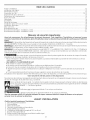
CONTENTS
Pre-lnstallation Requirements .......................................................................................................................................... 2
Electrical Requirements .................................................................................................................................................. 3
Gas Supply Requirements ........................................................................................................................................................ 3
Exhaust System Requirements ...................................................................................................................................... 3-5
Location of Your Dryer.................................................................................................................................................... 5
Rough-in Dimensions ..................................................................................................................................................... 6
Reversing Door Swing ................................................................................................................................................. 7
Unpacking ................................................................................................................................................................... 8
General Installation ....................................................................................................................................................... 8
Replacement Parts........................................................................................................................................................ 8
Mobile Home Installation ............................................................................................................................................... 9
Electrical Installation ..................................................................................................................................................... 9
Grounding Requirements .............................................................................................................................................. 10
Gas Connection .......................................................................................................................................................... 10
Electrical Connections--3-wire ........................................................................................................................................ 11
Electrical Connections--4-wire ........................................................................................................................................ 11
Francais.................................................................................................................................................................... 12-21
Espahol .................................................................................................................................. 22-31
SAFETY INSTRUCTIONS
Before beginning installation, carefully read these instructions. This will simplify the installation and ensure the dryer
is installed correctly and safely. Leave these instructions near the Dryer after installation for future reference.
NOTE: The electrical service to the Dryer must conform with local codes and ordinances and the latest edition of the National
Electrical Code, ANSI/NFPA70, or in Canada, the Canadian electrical code C22.1 part 1.
NOTE: The gas serviceto the Dryer must conform with local codes and ordinances and the latest edition of the National Fuel Gas
Code ANSI Z223.1, or in Canada, CAN/ACG B149.1-2000
NOTE: The Dryer isdesigned under ANSI Z 21.5.1 or ANSI/UL 2158 - CAN/CSA C22.2 No. 112 (latest editions) for HOME USE
only. This Dryer isnot recommended for commercial applications such asrestaurants or beauty salons, etc.
Your safety and the safety of others is very important.
We have provided many important safety messages in the Use & Care Guide, Operating Instructions, Installation Instructions and
on your appliance. Always read and obey all safety messages.
This isthe safety alert symbol. This symbol alerts you to hazards that can kill or hurt you or others. All safety messages
will be preceded by the safety alert symbol and the word "DANGER" or "WARNING". These words mean:
_ You will be killed or seriously injured if you don't follow instructions.
You can be killed or seriously injured ff you don't follow instructions.
All safety messages will identify the hazard, tell you how to reduce the chance of injury, and tell you what can happen if the
instructions are not followed.
Foryour safety the information in this manual must be followed to minimize the risk of fire or explosion or to
prevent property damage, personal injury or loss of life.
Do not store or use gasoline or other flammable vapors and liquid in the vicinity of this or any other appliance.
WHAT TODO iF YOU SMELL GAS
• Do not try to light any appliance.
• Do not touch any electrical switch; do not useany phone in your building.
Clear the room, building or area of all occupants.
Immediately call your gassupplier from a neighbor's phone. Follow the gas supplier's instructions.
If you cannot reach your gassupplier, call the fire department.
Installation and service must be performed by a qualified installer, service agency or the gas supplier.
PRE-INSTALLATION REQUIREMENTS
Tools and Materials Required for installation:
1. Phillips head screwdriver.
2. Channel-lock adjustable pliers.
3. Carpenter's level.
4. Flat or straight blade screwdriver.
5. Duct tape.
6. Rigid or flexible metal 4 inch (10.2 cm) duct.
7. Vent hood.
8. Pipe thread sealer (Gas).
9. Plastic knife.

ELECTRICAL REQUIREMENTS
ELECTRICDryer
CIRCUIT- individual 30 amp. branch circuit fused with 30
amp. time delay fuses or circuit breakers.
Use separately fused circuits for washers and dryers, and DO
NOToperate a washer and a dryer on the same circuit.
POWER SUPPLY- 3 wire or 4-wire, 240 volt, single phase, 60
Hz,Alternating Current.
]
POWER SUPPLYCORD KIT- 3 wire - the dryer MUSTemploy
a 3-conductor power supply cord NEMA 10-30 type SRDTrated
at 240 volt AC minimum, 30 amp., with 3 open end spade lug
connectors with upturned ends or closed loop connectors and
marked for usewith clothes dryers. See ELECTRICALCONNEC-
TIONS FORA 3-WIRE SYSTEM.
4 wire - The dryer MUSTemploy a 4-conductor power supply
cord NEMA 14-30 type SRDTor ST(as required) rated at 240
volt AC minimum, 30 amp., with 4 open end spade lug connec-
tors with upturned ends or closed loop connectors and marked
for use with clothes dryers. See ELECTRICALCONNECTIONS
FORA 4-WIRE SYSTEM.
(Canada - 4-wire power supply cord isinstalled on dryer.)
WARNING - Risk of Shock, Appliance grounded to neutral
conductor through a link. Grounding through the neutral link is
prohibited for (1) New branch circuit installations (2) mobile
homes; (3) recreational vehicles; and (4) areaswhere local codes
do not permit grounding through the neutral, (1)disconnect the
link from the neutral, (2) use grounding terminal or lead to
ground appliance in accordance with local codes and (3) con-
nect neutral terminal or lead to branch circuit neutral in usual
manner (if the appliance isto be connected by means of a cord
kit, use4-conductor cord for this purpose). USECOPPERCON-
DUCTOR ONLY.
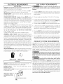
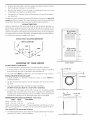
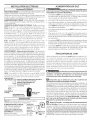
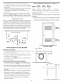
OUTLET RECEPTACLE- NEMA 10-30R receptacle to be located
so the power supply cord is accessible when the dryer is in the
installed position. (Canada - NEMA 14-30R receptacle.)
NEMA 10-30R NEMA 14-30R
GAS Dryer ]
CIRCUIT- Individual 15 amp. branch circuit fused with a 15
amp. maximum time delay fuse or circuit breaker.
POWER SUPPLY - 3 wire, 120 volt single phase, 60 Hz,
Alternating Current.
POWER SUPPLY CORD - The dryer is equipped with a 120 volt
3-wire power cord.
NOTE: Do not under any
circumstances remove
grounding prong from
plug.
PRONG
GAS SUPPLY REQUIREMENTS
Replace copper connecting pipe that is not
plastic-coated. Stainless steel or plastic-coated brass MUST
be used.
1. Installation MUSTconform with local codes,or in the absence
of local codes, with the National FuelGasCode, ANSIZ223.1
(latest edition).
2. The gas supply line should be of 1/2 inch (1.27 cm) pipe.
3. if codes allow, flexible metal tubing may be used to connect
your dryer to the gas supply line. The tubing MUST be
constructed of stainless steel or plastic-coated brass.
4. The gas supply line MUSThave an individual shutoff valve.
5. A 1/8 inch (0.32 cm) N.RT. plugged tapping, accessible for
test gauge connection, MUST be installed immediately
upstream of the gas supply connection to the dryer.
6. The dryer MUSTbe disconnected from the gas supply piping
system during any pressure testing of the gas supply piping
system at test pressures in excess of 1/2 psig (3.45 kPa).
7. Thedryer MUSTbe isolated from the gassupply piping system
during any pressure testing of the gas supply piping system
at test pressures equal to or less than 1/2 psig (3.45 kPa).
EXHAUST SYSTEM REQUIREMENTS
Use only 4 inch (10.2 cm) diameter (minimum) rigid or flexible
metal duct and approved vent hood which has a swing-out
damper(s) that open when the dryer is in operation. When the
dryer stops, the dampers automatically close to prevent drafts
and the entrance of insects and rodents. Toavoid restricting the
outlet, maintain a minimum of 12 inches (30.5 cm) clearance
between the vent hood and the ground or anyother obstruction.
The following are specific requirements for
proper and safe operation of your dryer. Failure to follow
these instructions can create excessive drying times and
fire hazards.
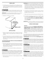
Do not install a dothes dryer with flexible
plastic venting materials. If your present system is made up
of plastic duct or metal foil duct, replace it with a rigid or semi-
rigid metal duct. InCanada and the United States if metal (foil
type) duct is installed, it must be of a specific type identified by
the appliance manufacturer assuitable for usewith clothes dry-
ers and in the United States must also comply with the Outline
for Clothes Dryer Transition Duct, ULstandard 2158A. Flexible
venting materials are known to collapse, be easily crushed and
trap lint. These conditions will obstruct clothes dryer airflow and
increase the risk of fire. Ensure the present duct is free of
any lint prior to installing dryer duct.

Correct Incorrect
L
DO
Correct
DON'T
Incorrect
- Risk of Fire - A clothes dryer must be ex-
hausted outdoors. Do not exhaust dryer into a chimney, a
wall, a ceiling, an attic, a crawl space or any concealed space
of a building A clothes dryer produces combustible lint. If the
dryer is not exhausted outdoors some fine lint will be expelled
into the laundry area. An accumulation of lint in any area of the
home can create a health and fire hazard. The dryer must be
connected to an exhaust outdoors. Regularly inspect the
outdoor exhaust opening and remove any accumulation of lint
around the outdoor exhaust opening and in the surrounding
area.
Do not allow combustible materials (for ex-
ample: clothing, draperies/curtains, paper) to come in con-
tact with exhaust system. Thedryer MUSTNOT beexhausted
into a chimney, a wall, a ceiling, or any concealed space of a
building which can accumulate lint, resulting in a fire hazard.
Exceeding the length of duct pipe or num-
ber of elbows allowed in the "MAXIMUM LENGTH" charts
can cause an accumulation of lint in the exhaust system. Plug-
ging the system could create a fire hazard, as well as increase
drying times.
Do not screen the exhaust ends of the vent
system, nor use any screws, rivets or other fastening means
that extend into the duct and catch lint to assemble the
exhaust system, Lint can become caught in the screen, on the
screws or rivets, dogging the duct work and creating a fire haz-
ard as well as increasing drying times. Use an approved vent
hood to terminate the duct outdoors, and sealall joints with duct
tape. All male duct pipe fittings MUSTbe installed downstream
with the flow of air.
Explosion hazard. Do not instafl the dryer
where gasoline or other flammables are kept or stored. If
the dryer is installed in a garage, it must be a minimum of 18
inches (45.7 cm) above the floor. Failure to do so can result in
death, explosion, fire or bums.
Number
of
90°
Turns
0
1
2
3
4
Number
of
90°
Turns
0
1
2
3
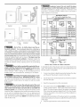
MAXIMUM LENGTH
of 4" (10,2 cm) Dia. Rigid Metal Duct
VENT HOOD TYPE
(Preferred)
(10.2 cm)
6oft.(l&28m)
52 ft.(is.84 m)
44 ft.(13.41 m)
32 ft.(9.75 m)
28 ft.(8.s3m)
MAXIMUM LENGTH
(6.35cm)
48ft.(14.63m)
40 ft.(12.19 m)
32ft. (9.75m)
24ft. (7.31m)
16ft. (4.87m)
of 4" (10,2 cm) Dia. Flexible Metal Duct
VENT HOOD TYPE
(Preferred)
3Oft. (9.14 m)
22 ft. (6.71 m)
14 ft. (4.27 m)
NOT RECOMMENDED
(6.35cm)
18ft. (5.49m)
14 ft. (4.27 m)
1oft. (3.OSm)
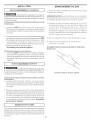
INSTALL MALE FITTINGS IN CORRECT DIRECTION
In installations where the exhaust system isnot described in the
charts, the following method must be used to determine if the
exhaust system is acceptable:
1. Connect an inclined or digital manometer between the dryer
and the point the exhaust connects to the dryer.
2. Setthe dryer timer and temperature to air fluff (cool down)
and start the dryer.
3. Read the measurement on the manometer.
4. The system back pressure MUSTNOTbe higher than 0.75
inches of water column. Ifthe system back pressure is less
than 0.75 inches of water column, the system isacceptable.
If the manometer reading ishigher than 0.75 inchesof water
column, the system istoo restrictive and the installation is
unacceptable.
Although vertical orientation of the exhaust systemisacceptable,
certain extenuating drcumstances could affect the performance
of the dryer:
• Only the rigid metal duct work should be used.

• Ventingverticalthrougharoofmayexposetheexhaustsystemtodown
draftscausinganincreaseinventrestriction.
• Runningtheexhaustsystemthroughan uninsulatedareamaycause
condensationandfasteraccumulationoflint.
• Compressionorcrimpingoftheexhaustsystemwillcauseanincreasein
ventrestriction.
Theexhaustsystemshouldbeinspectedandcleanedaminimumofevery 18
months with normal usage. The more the dryer isused, the more often you
should check the exhaust system and vent hood for proper operation.
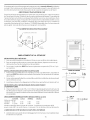
EXHAUST DIRECTION
All dryers shipped from the factory are set up for rear exhausting. However, on
electric dryers, exhausting can be to the right or left side of the cabinet or the
bottom of the dryer. On gas dryers, exhausting can be to the right side of the
cabinet or the bottom of the dryer. Directional exhausting can be accomplished
by installing Exhaust Kit, P/N 131456800, available through your parts distribu-
tor. Follow the instructions supplied with the kit.
EXHAUST DUCT LOCATING DIMENSIONS
4 3/8"
3 3/4"
3 3/4"
LOCATION OF YOUR DRYER
DO NOT INSTALL YOUR DRYER:
1. In an area exposed to dripping water or outside weather conditions.
2. In an area where it will come in contact with curtains, drapes, or anything
that will obstruct the flow of combustion and ventilation air.
3. On carpet. Floor MUSTbe solid with a maximum slope of 1 inch (2.54 cm).
INSTALLATION IN RECESSORCLOSET
1. A dryer installed in a bedroom, bathroom, recess or closet, MUST be
exhausted outdoors.
2. No other fuel burning appliance shall be installed in the same closet as the
Gasdryer.
3. Your dryer needs the space around it for proper ventilation.
DO NOT install your dryer in a closet with a solid door.
4. A minimum of 120 square inches (774.2 square cm) of opening, equally
divided at the top and bottom of the door, is required. Air openings are
required to be unobstructed when a door isinstalled. A Iouvered door with
equivalent air openings for the full length of the door isacceptable.
MINIMUM INSTALLATION CLEARANCES- Inches (cm)
SIDES REAR TOP FRONT
Alcove 0(0cm) 0(0cm)
Closet 0 (0 cm) 0 (0 cm) 1 (2.54 cm)
Closet door ventilation required: 2 Iouvered openings each 60 square inches
(387 square centimeters) -- 3 inches (7.6 cm) from bottom and top of door.
This dryer MUST be exhausted outdoors.
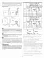
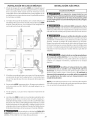
5 Thefollowing illustrations show minimum clearance dimensions for proper
operation in a recessor closet installation.
5
CLOSET DOOR
il
ii ==
--_,*--0 (Ocm)
H
II
II 1 ==
II
_11 _
0"(0,, cm)
(2.54 cm) _,,4

23%"
(60.33)
24"
{60.96)
25/8"
(8.67)
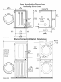
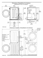
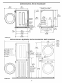
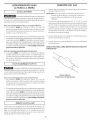
Dryer Installation Dimensions
Free-Standing & Under Counter
Electrical supply
on rear of unit
/
/
T 5W'
(13.97) _
13W'
29%" (34.29) 23/8"
_875..(f4.931 75.57) ; To rear (6.03)
',To base '_
:exhaust and base
exhausts --_
4.375"(11.12)
To side Jr 0
:exhausts
5.0"(12.7) 5"
height for rear, __ __ .
right, left vent T Gas sUp_ply
pipe on rear
15/8" of unit
(4.13) - -
27"
" (68.58)
22¾"
(57.79)
243/8"
(61.91)
27"
inches (cm)
Stacked Dryer Installation Dimensions
__ 27"
(68.58)
34 _
(86.."
,11---
6)
To front of cabinet
28.25"(71.76)
To clear kobs
28.75"(73.03)
To clear door
29.5"(74.93)
To clear open door
53"(134.62)
41.00"
(97.16)
Center line
height for
rear, right,
left vents
72.00"
(172.88)
Gas
supply iI
p pe on
rear of
inches (cm)
_L
t 2.25"
(5.72)
Electrical
supply on
rear of
unit

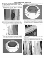
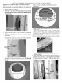
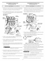
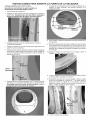
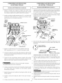
DRYER DOOR REVERSAL INSTRUCTIONS
Be sure to wear gloves while reversing the door assembly.
You will need a #2 square head drive screwdriver, a Phillips head
screwdriver and pliers.
1. Open the dryer door.
2. Remove the two screws that secure the door hinge to the front panel.
Remove the bottom screw first. Support the door assembly
firmly before removing the top screw.
7. Remove the two hinge attachment screws, one square plug, two
round plugs and one metal strike from the inner door.
attac hment
screw
3. Hold the door near the top and bottom and lift to remove the door.
4. Place door assembly face down on a padded, flat surface.
5. Pull out the two round plugs and slide the rectangular plug up and out
of the front panel. Use care to avoid scratching the surface or damaging
the plugs. Reinstall the plugs in Step 9.
Rectan
8.
9.
Rotate the hinge and reattach it to the opposite side of the inner door.
Dispose of the old metal strike and install the new strike (included in
the literature pack) in the opposite side of the inner door. Reinstall the
round plugs and square plug in the holes left by the hinge and hinge
screws.
10. Remove the hinge cutout plug. Rotate it and install it on the opposite
side of the outer door.
6.
Remove the five longer screws (1 through 5) and the two shorter
screws (6 and 7) that attach the inner door to the outer door. Do not
remove any other screws at this time. Separate the inner door
from the outer door.
11. Reattach the inner door to the outer door using the seven screws
removed in Step 6.
12. Holding the door at the top and bottom, insert the hinge post in the "T"
slot in the front panel and lower to align the screw holes. While
supporting the door, install the two screws removed in Step 2. Install
the top screw first.
13. Close the door.
7

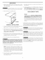
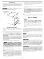
UNPA CKIN G
1. Using the four shipping carton corner posts (two on each
side), carefully lay the dryer on its left side and remove the
foam shipping base.
To prevent damage, do not use the control
panel asa means to pick up or move the dryer.
2. Return the dryer to an upright position.
GENERAL iNSTALLATiON
Connect the exhaust duct to outside exhaust system (see
pages 3 and 4). Use duct tape to seal all joints.
,
With the dryer in its final position, adjust one or more of the
legs until the dryer is resting solid on all four legs. Place a
level on top of the dryer. The dryer MUST be level and
resting solid on all four legs.
3. Plug the power cord into a grounded outlet. NOTE:Check
to ensure the power is off at circuit breaker/fuse box before
plugging the power cord into the outlet.
4. Turn on the power at the circuit breaker/fuse box.
Before operating the dryer, make sure the
dryer area is clear and free from combustible materials,
gasoline, and other flammable vapors. Also see that noth-
ing (such as boxes, dothing, etc.) obstructs the flow of
combustion and ventilation air.
5. Run the dryer through a cycle check for proper operation.
NOTE: On gas dryers, before the burner will light, it is nec-
essaryfor the gas line to be bled of air. If the burner does
not light within 45 seconds the first time the dryer isturned
on, the safety switch will shut the burner off. If this happens,
turn the timer to "OFF" and wait 5 minutes before making
another attempt to light.
6. If your dryer does not operate, please review the "Avoid
Service Checklist" located in your Use and Care Guide be-
fore calling for service.
,
,
Placethese instructions in a location near the dryer for fu-
ture reference.
To stack your dryer on a compatible washer, visit web site
www.frigidaire.com, call your local dealer or call the Toll
Freenumber (1- see- 444 - 4944) to find your localdistribu-
tor to purchase stacking kit accessorypart number STACKIT3.
REPLA CEMENT PARTS
Pedestal
A pedestal accessory, Model No. APWD15W (White),
A PWD 15GB (Glacier Blue), A PWD 15P(Pla tinum) and
APWD15E(Black), specificallydesigned for this dryermay
be usedwhen elevating the dryer for easeof use. Failure
to use accessories certified by the manufacturer could
result in personal injury, property damage or damage to
the dryer.
If replacements parts are needed for your dryer, contact the
source where you purchased your dryer, call 1-800-944-9044,
or visit our website, www.frigidaire.com, for the Frigidaire Com-
pany Authorized Parts Distributor nearest you.
Label all wires prior to disconnection when ser-
vicing controls. Wiring errors can cause improper and danger-
ous operation. Verify proper operation after servicing.
Destroy the carton and plastic bags after the
dryer is unpacked. Children might use them for play. Cartons
covered with rugs, bedspreads, or plastic sheets can become
airtight chambers causing suffocation. Placeall materials in a
garbage container or make materials inaccessible to children.
The instructions in this manual and all other
literature included with this dryer are not meant to cover every
possible condition and situation that may occur. Good safe prac-
tice and caution MUST be applied when installing, operating
and maintaining any appliance.

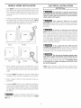
MOBILE HOME INSTALLATION
Dryer MUSTbe exhausted outside (outdoors, not beneath
the mobile home) using metal ducting that will not sup-
port combustion. Metal ducting must be 4 inches (10.16
cm) in diameter with no obstructions. Rigid metal duct is
preferred.
,
If dryer isexhausted through the floor and area beneath
the mobile home is enclosed, the exhaust system MUST
terminate outside the enclosure with the termination se-
curely fastened to the mobile home structure.
DO
\, /
• -- ,===/
L
Correct
f
DO
k J_ i
' : i
Correct _4
Incorrect
Incorrect _,
,
When installing a gas dryer into a mobile home, a provi-
sion must be made for outside make up air.This provision
isto be not lessthan twice the area of the dryer exhaust
outlet.
4. This dryer MUSTbe fastened to the floor. Mobile Home
Installation Kit No. 346764 is available from your dealer.
5. Refer to pages 3 and 4 for other important venting re-
quirements.
, InstallationMUSTconform to current Manufactured Home
Construction & Safety Standard (which isa Federal Regu-
lation Title 24 CFR-Part32-80) or when such standard is
not applicable, with American National Standard for Mo-
bile Homes.
ELECTRICAL INSTALLATION
{ ELECTRICDryer ]
The following are specific requirements
for proper and safe electrical instaflation of your dryer.
Failure to follow these instructions can create electrical
shock and/or a fire hazard.
This appliance MUST be properly
grounded, Electrical shock can result if the dryer is not prop-
erlygrounded. Follow the instructions in this manual for proper
grounding.
Do not use an extension cord with this
dryer. Some extension cords are not designed to withstand
the amounts of electrical current this dryer utilizes and can
melt, creating electrical shock and/or fire hazard. Locate the
dryer within reachof the receptacle for the length power cord
to be purchased, allowing some slack in the cord. Refer to
the pro-installation requirements in this manual for the proper
power cord to be purchased.
A U.L approved strain refief must be
installed onto power cord, If the strain relief isnot attached,
the cord can be pulled out of the dryer and can be cut by any
movement of the cord, resulting in electrical shock.
Do not use an aluminum wired recep-
tacle with a copper wired power cord and plug (or wce
versa), A chemical reaction occurs between copper and alu-
minum and can cause electrical shorts. The proper wiring
and receptacle is a copper wired power cord with a cop-
per wired receptacle.
NOTE: Dryers operating on 208 volt power supply will have
longer drying times than operating on 240 volt power supply.
The dryer isdesigned under ANSIZ 21.5.1 or
ANSI/UL2158 - CAN/CSA C22.2 (latest editions) for HOME
USEonly.
9

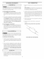
GROUNDING REQUIREMENTS GAS CONNECTION
USA ELECTRICDryer
improper connection of the equipment ground-
ing conductor can result in a risk of electrical shock. Check
with a licensed electrician if you are in doubt asto whether
the appliance isproperly grounded.
For a grounded, cord-connected dryer:
1. The dryer MUSTbe grounded. In the event of a malfunc-
tion or breakdown, grounding will reduce the risk of elec-
trical shock by a path of least resistance for electrical cur-
rent.
,
If your dryer isequipped with a power supply cord having
an equipment-grounding conductor and a grounding plug,
the plug MUST be plugged into an appropriate, copper
wired receptacle that isproperly installed and grounded in
accordance with all local codes and ordinances. If in doubt,
call a licensed electrician. Do not modify plug pro-
vided with the appliance.
For a permanently connected dryer:
1. The dryer MUSTbe connected to a grounded metal, per-
manent wiring system; or an equipment grounding con-
ductor must be run with the circuit conductors and con-
nected to the equipment-grounding terminal or lead on
the appliance.
Canadian ELECTR/CDryer
]
improper connection of the equipment ground-
ing conductor can result in a risk of electrical shock. Check
with a licensed electrician if you are in doubt asto whether
the appliance isproperly grounded.
Fora grounded cord-connected dryer:
,
,
,
,
Removethe shipping cap from gas pipe at the rear of the
dryer.
NOTE: DO NOTconnect the dryer to L.Rgasservicewith-
out converting the gas valve. An L.R conversion kit must
be installed by a qualified gas technician.
Connect a 1/2 inch (1.27 cm)I.D, semi-rigid or approved
pipe from gas supply line to the 3/8 inch (0.96 cm) pipe
located on the back of the dryer (see pages 6 and 7). Use
a 1/2 inch to 3/8 inch (1.27 cm to 0.96 cm) reducer for a
connection. Apply an approved thread sealer that is re-
sistant to the corrosive action of liquefied gases on all
pipe connections.
Open the shutoff valve in the gas supply line to allow gas
to flow through pipe.
Testall connections by brushing on a soapy water
solution.
NEVER test for gas leaks with an open flame.
VALVE OPEN/GAS FLOW POSITION
,
The dryer must be grounded, in the event of a malfunc-
tion or breakdown, grounding will reduce the risk of elec-
trical shock by a path of least resistance for electrical cur-
rent.
,
,
Since your dryer is equipped with a power supply cord
having an equipment-grounding conductor and a ground-
ing plug, the plug must be plugged into an appropriate
outlet that isproperly installed and grounded in accordance
with all local codes and ordinances. If in doubt, call a li-
censed electrician. Do not modify plug provided with
the appliance.
/ILL 6AS Dryers 1
The dryer isequipped with a three-prong (grounding) plug
for your protection against shock hazard and should be
plugged directly into a properly grounded three-prong
receptacle. Do not cut or remove the grounding prong
from the plug.
10

[
1.
,
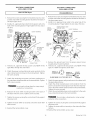
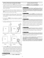
ELECTRICALCONNECTIONS
FOR 3- WIRE SYSTEM
USA ELECTRICDryer
]
Removethe screws securing the terminal block accesscover
and the strain relief mounting bracket located on the back of
the dryer upper corner.
Install a U.L.approved strain relief into the power cord entry
hole of the mounting bracket. Finger tighten the nut only at
this time.
GREEN
GROUND
SCREW
SILVERTERMINAL
NEUTRAL
GROUND
WIRE
NUT
TIGHTEN NUT
TO THESE
THREADS
RELIEF
MOUNTING
BRACKET
POWER CORD
3. Thread a U.L. approved 30 amp. power cord, NEMA 10-30
type SRDT,through the strain relief.
4. Attach the power cord neutral (center wire) conductor to the
silver colored center terminal on the terminal block. Tighten
the screw securely.
5. Attach the remaining two power cord outer conductors to
the outer brasscolored terminals on the terminal block. Tighten
both screws securely.
Do not make a sharp bend or crimp wiring/
conductor at connections.
6. Reattach the strain relief mounting bracket to the back of
the dryer with two screws. Tighten screws securely.
7. Tighten the screws securing the cord restraint firmly against
the power cord.
8. Tighten the strain relief nut securely so that the strain relief
does not turn.
9. Reinstall the terminal block cover.
ELECTRICALCONNECTIONS
FOR 4- WIRE SYSTEM
[
1.
,
USA ELECTRICDryer
J
Remove the screws securing the terminal block accesscover
and the strain relief mounting bracket located on the back of
the dryer upper corner.
Install a U.L. approved strain relief in the entry hole of the
mounting bracket. Finger tighten the nut only at this time.
GREEN POWER CORD
GREEN GROUND WIRE
GROUND -_'-'T-q.-- SILVERTERMINAL
SCREW I_"_;J_ _'_'_ _/
J_ ___ TERMINAL BLOCK
! , j/ MOUNTING
/ _/ / BRACKET.
'POWER CORD
3. Remove the ground wire from the green ground screw
located above the terminal block.
4. Thread a U.L. approved 30 amp power cord, NEMA 14-30
type STor SRDTthrough the strain relief.
ONOUCTOR/>WH,
_ Z _F_ED
30 AMP NEMA 14-30 TYPE SRDT OR ST _GREEN
5. Attach the green power cord ground wire to the cabinet with
the green ground screw.
6. Attach the white (neutral) power cord conductor from the
power cord and the neutral ground wire from the dryer har-
nessto the silver-coloredcenter terminal on the terminal block.
Tighten the screw securely.
7. Attach the red and black power cord conductors to the outer
brass-colored terminals on the terminal block.
Do not make a sharp bend or crimp wiring/
conductor at the connections.
8. Tighten the screws securing the cord restraint firmly against
the power cord.
9. Tighten the strain relief nut securely sothe strain relief does
not turn.
l O.Reinstall the terminal block accesscover.
11 Printed in U.S.A.

Table des matieres
Avant I'installation ............................................................................................................................................................ 12
Installation _lectrique .................................................................................................................................................... 13
Alimentation en gaz......................................................................................................................................................... 13
Evacuation de I'air .................................................................................................................................................. 13-1 5
Emplacement de la s_cheuse........................................................................................................................................... 15
Dimensions de I'emplacement ................................................................................................................................. 16
Porte r_versible ............................................................................................................................................... 17
D_ballage ..................................................................................................................................................... 18
Installation .......................................................................................................................................................... 18
Pi_ces de rechange ......................................................................................................................................................... 18
Installation dans une maison mobile .................................................................................................................................. 19
Installation _lectrique ....................................................................................................................................................... 19
Mise _ la terre ................................................................................................................................................................ 20
Branchement du gaz............................................................................................................................................................. 20
Branchement _lectrique - Installation _ 3 fils........................................................................................................................ 21
Branchement _lectrique - Installation _ 4 fils........................................................................................................................ 21
Mesures de securite importantes
Avant de commencer, lire attentivement le prOsent document. Cola simplifiera I'installation et assurera la pose
correcte et s_curitaire de la s_cheuse. AprOs I'installa tion, laisser ce document b proximit_ de la s_cheuse pour rOf_rence
future.
REMARQUE :L'alimentation _lectrique dela s_cheusedolt respecter loscodes et ordonnances Iocauxainsi que I'_dition la plusr_cente
du Code ANSI/NFPA70 (Etats-Unis), ou au Canada, le Code canadien d'_lectricit_, ACNOR C22.1, 1 re pattie.
REMARQUE :L'alimentation engaz de la s_cheusedolt respecter lescodes etordonnances Iocaux ainsi que I'_dition la plus r_cente du
Code ANSI Z223.1 (Etats-Unis), ou au Canada, le code CAN/ACG B149.1-2000.
REMARQUE : Las_cheuseest conc ue conform_ment au code ANSIZ21.5.1 ou ANSI/UL2158 - CAN/AC G C22.2 No. 112 (l'_dition la
plus r_cente) pour un USAGEDOMESTIQUEseulement. Cette s_cheuse n'est pas recommand_e pour une utilisation commerciale,
comme par exemple dans un restaurant ou dans un salon de coiffure, etc.
Pour votre s_curit_, suivre los directives _nonc_es dans le present guide afin de minimiser los risques d'incendie,
d'explosion, de dommages materiels, de blessures et de mort.
- Ne pas entreposer ni utiliser d'essence ou autres liquides ou produits inflammables _ proximit_ de cette s_cheuse ou de tout
autre appareil m_nager.
- QUE FAIRE S'IL YA UNE ODEUR DE GAZ
• Ne mettre en marche aucun appareil.
• Ne toucher aucun interrupteur _lectrique; n'utiliser aucun t_l_phone dans I'immeuble.
• Faire sortir tous los occupants de la piece, de I'immeuble ou de la zone avoisinante.
• Appeler la fournisseur de gaz imm_diatement en utilisant le t_l_phone d'un voisin. Suivre los directives du fournisseur de
gaz.
• S'il est impossible de joindre le fournisseur de gaz, appeler le service de protection des incendies.
L'installation et los r_parations doivent gtre effectuges par un service de rgparation, un technicien qualifig ou le fournisseur de gaz.
Votre s_curit_ et celle des autres est tr_s importante.
Nous donnons de nombreux messagesde sgcuritg importants dans ce manuel et survotre appareil mgnager. Assurez-vous de toujours
life tous los messages de sgcuritg et de vous y conformer.
Voici le symbole de mise en garde. Ce symbole met en garde contre los risques pouvant entratner le dgcgs ou des blessures
sol ou aux autres. Tous losmessagesrelatifs _la sgcuritg sont prgcgdgs du symbole de mise en garde et du terme <<DANGER
>>ou <<AVERTISSEMENT>>.Cos termes signifient •
_ L'utilisateur sera tug gravement blessg s'il ne suit pas cosdirectives.
_ L'utilisateur peut gtre tug ou gravement blessg s'il ne suit pas cos directives.
Tous los messages relatifs b la s_curit_ indiquent le risque, comment r_duire le risque de blessure et ce qui peut
survenir si on ne suit pas les directives.
AVANT L'INSTALLATION
Outils et mat_riei requis pour l'installation :
1. Tournevis_ pointecruciforme
2. Pinto multiprise
3. Niveau de menuisier
4. Tournevis _ pointe plate ou _ lame droite
5. Rubanadhgsif pour conduits
6. Conduite en mgtal rigide ou souple de 10,2 cm (4 po)
7. Bouche d-gvacuation de I'air
8. Ruban ou p_te d'gtanchgitg pot joints filetgs (modgle _ gaz)
9. Couteau _ mastic en plastique
12

INS TA LLATION L'LECTRIQ UE
[ S#cheusesELECTR/QUES ]
CIRCU/TELECTRIQUE- Circuit de d_rivation distinct de 30 A avec
fusibles _ retardement ou disjoncteurs d'au 30 A.
Utilisez des circuits avec un disjoncteur ou fusible s@ar_ pour les
machines _ laver et s_cheuses, et NE PASfaire fonctionner une
machine _ laver et une s_cheuse sur un m_me circuit.
ALIMENTATIONELECTRIQUE- 3 illsou 4 ills, 240 volts, une phase,
60 Hz, courant alternatif. (Canada - 240 volts, une phase, 60 Hz,
courant alternatif.)
CORDOND fAL/MENT.47/ONELECYR/QUE- 3 fils - Ia s6cheuse
DO/T6tre dot_e d'un cordon d'alimentation dectrique a 3 ills
NEMA 10-30, c.a, 30 A, de type SRDTd'une capacit6 minimale
de 240 volts, avec fiche en L _ 3 broches _ extr6mit_s ouvertes,
relev_es ou ferm6es, OUd'un cordon d'alimentation 6Iectrique
4 fils NEMA 14-30, c.a, 30 A, de type SRDTou ST(selon Ie cas)
d'une capacit6 minimale de 240 volts, avec 3 connecteurs _ cosse
ouverte recourb6e vers Iehaut aux extr6mit_s ou 3 connecteurs
cosseferm_e, concus pour Ie raccordement d'une s6cheuse.
4 fils - Elle DO/T6tre dot_e d'un cordon d'alimentation a 4 ills
NEMA 14-30, c.a, 30 A, de type SRDTou ST(selon le cas)d'une
capacit6 minimale de 240 volts, avec4 connecteurs _ cosseouverte
recourb6e vers Ie haut aux extr6mit6s ou 4 connecteurs a cosse
ferrule, concus pour le branchement d'une s_cheuse. Voir la
section INSTALLATIONELECTRIQUEpour plus de d_tails.
AVERTISSEMENT-Risque de choc _lectrique. Unappareil mis
la terre _ I'aide d'un lien ou c_ble conducteur neutre. La mise
laterre _ I'aide d'un conducteur ou c_ble neutre est interdite dans
lescas suivants : (1) lesinstallations de nouveau circuit d_vir_ (2)
lesmaisons mobiles (3)les v_hicules r_cr_atifs ou caravanes et (4)
lesr_gions ou lescodes Iocaux interdisent la mise _ laterre _ I'aide
d'un c_ble ou conducteur neutre. (1) D_branchez le conducteur
ou c_ble du neutre, (2) utilisez la borne de mise _ laterre ou le c_ble
de mise _ la terre de I'appareil conform_ment aux codes Iocaux et
(3)connectez ou branchez la borne neutre ou lec_ble au neutre du
circuit d_vir_de lamani_re habituelle (siI'appareil dolt _tre connect_
I'aide d'un cordon, utilisez un cordon _ 4 c_bles ou ills pour ce
faire). N'UTILISEZQUE DESCABLESOU FILSENCUIVRE.
PR/SE- PriseNEMA 10-30R (3 alv_oles) ou prise NEMA 14-30R
(4 alv_oles) plac_e de facon que le cordon d'alimentation
dectrique soit accessible une fois la s_cheuse en place.
ALIMENTATIONII , . .
teLECTRIQUE _ _ BOJTE A FUSIBLES PRINCIPALE NEUTRE A 3
I _ FILS12e-2.4eVOLTS60 CYCLES
I_ _ _ FUSIBLES A RETARDEMENT OU
DISJONCTEUR DE 30 A_-_.. FIL NEUTRE
PRISE MURALE
(CUIVRE) NEMA I 0-30R
SOUS RIeSERVE DES (CUIVRE)
EXIGENCES LOCALES
[ S#cheuses_GAZ i
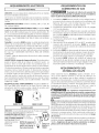
CiRCUiT- D_rivation distincte de 15 A avecfusible
retardement ou disjoncteur d'au plus 15 A. _
ALIMENTATION_'LECTRIQUE- REMARQUE: _J|l I|I
3ills, 120volts, une phase, aucun cas ( \\ _ _j
60 Hz,courant alternatif, retirer la \ } _k
CORDOND'ALIMENTATION broche de '\ / J \
_'LECTRIQUE- Las_cheuseest mise a la terre \\ IjI BROCHE DE
pourvued'uncordon de la fiche. _ MISE A LA
d'alimentation _lectrique _ 3 ills de 120 volts. TERRE
ALIMENTATION EN GAZ
Remplacer le tuyau de raccordement en
cuivre non recouvert de plastique. II FAUT utiliser du laiton
inoxydable ou recouvert de plastique.
1. L'installation DOITrespecter lescodes Iocaux, ou s'il n'existe pas
de codes Iocaux, le code ANSI Z223.1 (l'_dition laplus r_cente)
ou au Canada, le Code actuel CAN/CGA B149.
2. Laconduite d'alimentation en gazdolt mesurer 1,27 cm (1/2 po).
3. Si lescodes le permettent, un tuyau en m_tal flexible peut _tre
utilis_ pour connecter la s_cheuse _ I'alimentation en gaz. Le
tuyau DOIT_tre fabriqu_ en acier inoxydable ou en cuivre avec
un rev_tement de plastique.
4. La conduite d'alimentation en gaz DOITcomporter unrobinet
d'arr_t distinct.
,
Une prise de 0,32 cm (1/8 po) NPT accessible pour le
branchement d'u nmanom_tre DOIT_tre install_e tout juste en
amont du branchement de la conduite d'alimentation en gaz
sur la s_cheuse.
6. La s@cheuseDOIT@tre d@branch@ede la canalisation de gaz
pendant toute v@rificationde pression de I'alimentation en gaz
des pressions qui d@assent 3,45 kPa(1/2 Ib/po_).
7. Las@cheuseDOIT@tre isol@ede lacanalisation de gaz pendant
toute v@rification de pression de I'alimentation en gaz _ des
pressions @galesou inf@rieures_ 3,45 kPa(1/2 Ib/po_).
EVA CUATION DE L'AIR
Utiliser uniquement un conduit en metat rigide ou souple de 10,2
cm (4 po) de diam_tre (minimum) ainsi qu'une bouche
d'_vacuation approuv_e dont les clapets s'ouvrent !orsque la
s_cheuse fonctionne. Quand Ia s6cheuse s'arr6te, Ies clapets se
ferment automatiquement pour @iter Iescourants d'air et I'entr_e
d'insectes ou de rongeurs. Afin de ne pasobstruer Iasortie d'air,
laisser une distance minimum de 30,5 cm (12 po) entre la bouche
d'_vacuation et le sol ou tout autre obstacle.
Les directives suivantes ont #t_ #mises afin
d'assurer /'insta//ation appropri4e et s#curitaire de votre
s#cheuse. Le d#faut de respecter ces directives risque
d'entrafner des chocs #/ectriques e_/ou un incendie,
N'installez pas la S_cheuse avec des materiels de
ventila tion en ma tieres plastiques flexibles.
Sila conduite existante est en plastique ou en papier m_tallique, la
remplacer par une conduite en m_tal rigide ou flexible. Au Canada
etaux Etats-Unissileconduit estde m_tal (type feuille d'aluminium),
celui-ci dolt _tre d'un type sp_cifique identi% par le fabricant,
recommand_ pour I'utilisation avec des S_cheuses; et aux Etats-
Unis il dolt en outre remplir la norme UL215% Lesmat_riaux de
ventilation fiexibles peuvent s'abimer facilement et recueillir du
duvet. Cesconditions obstrueront lacirculation d'air de la %cheuse
de v_tements et augmenteront lerisque d'incendie. S'assurer
qu'il n'y a pas de charpie clans la conduite existante avant
d'installer la conduite de la s_cheuse.
V_ -Risque d'incendie- une S_cheuse de v_tement doit _tre
a_r_ b I'air libre, N'a_rez pas la S_cheuse dans une chemin_e,
une paroi, un plafond, un espaceferm_ ou aucun espacecach_ du
b_timent. Une s_cheuse_linge produit de la charpie combustible.
Si Fair n'_tait pas repouss_ _ I'ext_rieur de la maison de petites
particules de charpie seretrouveraient dans lapiece ou est insta%e
la s_cheuse. Toute accumulation de charpie dans la maison peut
presenter des risques pour la sant_ et des risques d'incendie.
13

La s_cheuse dolt _tre connect_e b une bouche d'_vacua tion
vers I'ext_rieur du b_timent ou de I'immeuble. Vous devez
inspecter r_guli_rement I'_vent ext_rieur et enlever toute
accumulation de charpie autour de I'@ent et dans la cavit_ du
conduit d'@acuation.
I
h
Correct Incorrect
_1_ Nelaisseraucun mat_riau inflammable (comme desv_tements
destentures des rideaux ou du papier) entrer en contact avec les
conduits d'_vacuation. L'air de la s_cheuse NE DOlT PAS _tre
@acu_dansunechemin@, un mur, un plafond nitout espaceferm_
d'un batiment ou la charpie pourrait s'accumuler et presenter un
risque d'incendie.
_ Augmenter laIongueurduconduit rigideou lenombre decoudes
permis au tableau _LONGUEURMAXIMUM_ risque de r_duire la
capacit_ d'@acuation du circuit. Obturer le circuit peut cr@r un
risque d'incendie et augmenter le temps de s_chage.
_ N'obstruez les du tube de ventilation utilisez
pas
extr_mit_s ni
desvis, rivetsou autres moyens de fixation qui peuvent obstruer le
conduit et recueillir du duvet. L'engorgement subsequent risquerait
de ralentir letemps de s_chage,voirede causerun incendie. Installer
une bouche d'@acuation approuv@ a I'ext_rieur et scellertousles
joints a I'aide d'un ruban adh_sif a conduits. Tousles raccords de
condu it malesDO/Y£4/7-_tre install_s dans lesensde lacirculation
d'air.
Risques d'explosion. Ne pas installer la
s_cheuseaunendroit o0 I'on qarde delagazolineou tout autreproduit
inflammable. Si la s_cheuse est install@ dans un garage, elle dolt
_trea un minimum de45,7 cm (18 po) au-dessusdu plancher. Toute
d_rogation pourrait provoquer la mort, I'explosion, I'encendie ou
lesbr01ures.
Nombre de
coudes
90 °
o
14
0
1
2
3
4
LONGUEUR MAXIMUM
d'une conduite en m_tal rigide de
10,16 cm (4 po) de diam.
TYPEDE GRILLEDE SORTIE
(Recommand_)
cm
(4 po)
18,28 m
15,84m
13,41 m
9,75 m
8,53 m
volet
(60 po) 14,63rr
(52 po)
(44 po)
(32 po)
(28 po)
(48 po)
12,19m (40 po)
9,75 m(32 po)
7,31 m(24 po)
4,87 m(16 po)
Nombre de
coudes
90°
0
1
2
3
LONGUEUR MAXIMUM
d'une conduite en m_tal flexible de
10,16 cm (4 po) de diam.
TYPEDE GRILLEDE SORTIE
(Recommand_)
,,_ a volet
cm
(4po)
9,14 m (30 po)
6,71 m (22 po)
4,27 m (14 po)
5,49 m(18 po)
4,27 m (14 po)
3,05 m (10 po)
NON RECOMMANDE
POSERLESRACCORDS MALES DANS LA BONNE DiRECTiON
Pour lesinstallations dont le circuit d'6vacuation n'est pasd6crit
dans lestableaux, il faut utiliser la m6thode suivante sile circuit
d'@acuation n'est pasacceptable:
1. Brancher un manom6tre digital ou a tube inclin6 entre la
s6cheuse et le raccord d'@acuation de la s6cheuse.
2. R6glerla minuterie de la s6cheuse et la temp6rature a air froid
(refroidissement) et d6marrez la s6cheuse.
3. Life la mesure indiqu@ au manom6tre.
4. Labasse pression ne dolt pas 6tre sup_rieure a 0,75 pouce de
colonne d'eau. Sila bassepression est inf6rieure a0,75 pouce
de colonne d'eau, lecircuit estacceptable. Sila lecture indique
une pression sup6rieure a 0,75 pouce de colonne d'eau, la
capacit6 du circuit est insuffisante etl'installation inacceptable.
Bien qu'un circuit vertical soit acceptable, certaines circonstances
att6nuantes peuvent influencer la performance de la s6cheuse.
IIfaut utiliser uniquement des conduits rigides en m6tal.
Unesortie sur un toit d'un circuit vertical peut exposer celui-ci a
un contre-tirage et ainsi r6duire sacapacit6 d'@acuation.
L'isolant que dolt traverser un tel circuit peut causer de la
condensation et ainsir6duire lacapacit6 d'6vacuation du circuit.
Un circuit d'_vacuation comprim6 ou ondulant peut voir sa
capacit6 d'@acuation r6duite.

IIfautinspecterlecircuitd'_vacuationetlenettoyeraumoinsatousles 18mois d'utilisation
normale. Plusla s_cheuse est utilis_e, plus il faut proc_der souvent a une v_rification du
bon fonctionnement du circuit d'_vacuation et du couvercle du registre ou de I'_vent.
DIRECTION DEL'_'VACUATION DEL'AIR
Toutes less#cheusesempaquet#es par I'usine sont concuesde facon _ceque I'#vacuation
de I'air sefasse_ I'arri_re. Toutefois, dans le casdess#cheuses#lectriques, I'#vacuation de
I'air peut sefaire sur ladroite ou surla gauche du bottler ou encore, sous las#cheuse. Dans
lecas dess#cheuses_ gaz, I'#vacuation de I'air peut sefaire sur la droite du bottler ou sous
la s#cheuse. On pout donc modifier I'orientation de I'#vacuation de I'air en installant un
ensemble d'#vacuation de I'air n° de piece 131456800 disponible chez d'un fournisseur de
pi_ces agr##. Suivre losdirectives qui accompagnent cot ensemble.
"" _'_LACEMENTDESBOUCHESD'_'VA CUATION
9,5 cm
(3 314po)
COMME SUR L'AUTRECOTE
15cm
(5 718po)
//
34 cm
-. _ "(131/2po)
11 cm
9,5 cm
(3 314po)
EMPLA CEMENT DE LA SECHEUSE
NE PASINSTALLERLA SL'CHEUSE:
1. Dans un endroit expos_ bun _coulement d'eau ou aux conditions atmosph_riques.
2. Dans un endroit ou elle serait en contact avec des rideaux, draperies ou tout cequi
obstruera le flux d'air de combustion et de ventilation.
3. Sur un tapis. Le plancher DOIT_tre ferme et presenter une pente de 2,54 cm (1 po)
au maximum.
INSTALLATION DANS UNEAL COVEOU UN PLACARD
1. Toute s_cheuse install_e dans une chambre _coucher, une sallede bain, une alc6ve ou
un placard DOIT_tre reli_e _une conduite d'_vacuation d'air seterminant _ I'ext_rieur
de la maison.
2. Aucun autre appareil br01antdu combustible ne dolt _tre install_ dansle m_me placard
que la s_cheuse au Gaz.
3. Las_cheuse a besoin d'un d_gagement suffisant pour permettre la circulation de I'air.
NEPASINSTALLER LA SE'CHEUSEDANS UN PLACARDPOURVU
D'UNEPOR TEPLEINE.
,
Une ouverture minimum de 774,2 cm2(120 po2)r_partie _galement entre le haut et le
has de la porte est requise. Cette ouverture ne dolt pas_tre obstru_e Iorsque la porte
est en place. Une porte _volets dont losouverturestotalisent la norme d_crite ci-dessus
est acceptable.
D_'GAGEMENTS MINIMAUX POUR L'INSTALLATION en po (cm)
D'AVANT COTES ARRIERE DESSUS
AIc6ve ou sous un
comptoir 0 (0) 0 (0) 0 (0) 0 (0)
Armoire 1 (2,54) 0 (0) 0 (0) 0 (0)
A@ration n@cessairedans la porte de I'armoire: 2 ouvertures _ persiennes de 60
pouces carr@s(387 cm cart@s)chacun - _ 3 pouces (7,6 cm) du haset du haut de la porte.
L 'A_'RATIONDE CETTESE'CHEUSESEFAIT VERSL 'EXTERIEUR.
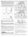
5. Losillustrations qui suiventdonnent led@gagementminimum pour une installation dans
une alc6ve ou un placard.
15
©
387,1 cm 2
(60 po_)
PORTE DU PLACARD
II
_l_ 0 era(0 po) 0 ¢m
ii (opo)
II
,, 2,54 cm
I_-Ii_
ii (1 po) _-li_ o cm(o po)
II II
i
i]

23%"
(60,33)
25/8"
(8.67)
inches (cm)
Dimensions D'lnstallation De Secheuse
Independant Et Sous Le Compteur
24"
(60,96)
22¾"
(57,79)
243/8"
(61,91)
5.875"(14.93)
',Aux
_chappements
_bas
29%"
:75,57)
4.375"(11.12)
Aux
_chappements J,
lat_raux
5.0"(12.7) 5"
ugneta,le (12,70)
centrale pour __
artiste, droit, --f
patti, passage
Alimentation
_lectrique
I'arri_re de I'appereil
/
/
De la sortie
d'_vacuation
arri_re et
de base
13W'
(34,29) 23/8"
" ' (6,03)
.,IF---
O 4!
--Conduit _" t 2.25"
d'alimentation en gaz & (5,72)
I'arri_re del'appareii
de l'unit_
27"
(68,58)
Dimensions Empilees D'lnstallation De Secheuse
[
Pour affronter le coffret
28.25"(71,76)
Aux boutons clairs
28.75"(73,03)
A la poign_e claire
de porte
29.5"(74,93)
A I'espace libre ouvrez
la porte
53"(134,62)
lif ................
72.00"
(172,88)
4.375"
(11,12)
Echappements
Lat_raux
41.00"
(97,16)
Ligne taille
centrale
pour arri_re,
droit, parti,
passage
Pipe
d'offre de
gaz sur i l
l'arri_re
de l'unit t
:;<.i
(34,29) _ ,,
I
38.25"
(97,16)
inches (cm)
16
Alimentation
61ectrique
-- sur l'arri_re
_nit_

INSTRUCTIONS D'INVERSION
Assurez=vous de porter des gants au moment d'inverser la 7.
porte.
Vous aurez besoin d'un tournevis a t_te carte, d'un autre a t_te
en etoile et de pinces.
1. Ouvrez ta porte de la secheuse.
2. Demontez tes deux vis de fixation de ta penture de ta charniere
de la porte au panneau avant. Demontez en premier les vis
inferieures. Tenez la porte fermement avant de demonter les
vis superieures.
DE PORTE DE SE CHEUSE
Retirez les deux vis de fixation de charniere, te bouchon
carte, tes deux bouchons ronds et la g_che en metal de la
contre-porte.
ronds
3,
4.
5.
Tenez ta porte par le bas et le haut et soulevez la porte pour la
retirer.
Placez la porte face vers le bas sur une surface plate et
rembourree.
Retirez les deux bouchons ronds, glissez te bouchon
rectangulaire et retirez-le du panneau avant. Prenez soin d'eviter
d'egratigner la surface ou d'endommager les bouchons.
8,
9.
Faites une rotation de ta charniere et fixez-ta du c6te oppose de
la contre-porte.
Jetez la vielle g&che en metal et posez ta nouvetle g&che
(comprise dans la trousse de documentation) sur te c6te
oppose de la contre-porte. Reposez tes bouchons ronds et te
bouchon carre dans les trous taisses par la charniere et les vis
de fixation de charniere.
10. Retirez le bouchon de decoupe de charniere. Faites une rotation
de la charniere et posez-ta du c6te oppose de la contre-porte.
6,
Recta
Bouct
Demontez tes cinq vis plus longues (1 a 5) et les deux plus
courtes (6 et 7) fixant ta contre-porte a la porte. Ne demontez
pas les autres vis presentement. Separez la contre-porte de
la porte.
11. Reposez la contre-porte a ta porte a t'aide des sept vis
retirees a l'etape 6.
12. Tenez ta porte par te haut et te bas pour inserer le touritlon de
charniere dans l'encoche en T du panneau avant et baisser
pour aligner les trous de vis. Tout en soutenant la porte, posez
les deux vis retirees a t'etape 2. Posez en premier la vis
superieure.
13. Fermez la porte de la secheuse.

DEBALLAGE
,
A I'aide desquatre coins de protection de I'emballage (deuxsur
chaque c6t_), d_poser d_licatement la s_cheuse sur son c6t_
gauche et retirer le morceau de mousse plac_ sous la s_cheuse
pour I'exp_dition.
Pour ne pasendommager la s_cheuse,ne pas
soulever ou d_placer la s_cheuse par le panneau de commande.
REMARQUE : Sila s_cheuse dolt _tre install_e sous un comptoir,
le panneau du dessuspeut _tre d_mont_ pour I'installation.
2. Remettre la s_cheuse _ la verticale.
REMARQUE: Dans le casdes s_cheuses_ gaz, la conduite dolt
_tre vid_e de son air avant que le br01eur ne puisse s'allumer.
Si le br01eurne s'allume pasdans les45 secondes qui suivent
le premier d_marrage, I'interrupteur de s0ret_ _teint
automatiquement le br01eur. Si cela se produit, remettre la
minuterie _ <<OFF>>et attendre 5 minutes avant de tenter une
nouvelle fois d'allumer le br01eur.
6. Si la s_cheuse ne fonctionne pas, passer en revue la section
de d_pannage inclus dans le Guide de I'utilisateur avant
d'appeler un centre de service.
7. Placercette notice pros de la s_cheuse pour r_f_rence future.
,
Pourempiler votre Secheusesurune Laveusecompatible, visitez
le site Web www,#igidaire.cern, appelez votre revendeur
local ou appelez le num_ro sanscoot (1 see-444- 4944) pour
trouver votre distributeur local et acheter la piece accessoire
num_ro STACKIT3.
MORCEAU
_DE MOUSSE
SBALLAGE
INSTALLATION
,
,
Relierlesconduits d'_vacuation d'air _ laconduite d'_vacuation
ext_rieure. Utiliser un ruban adh_sif pour conduites pour sceller
lesjoints.
Unefois las_cheusedans sonemplacement d_finitif, ajuster les
pieds de nivellement jusqu'_ ce que la s_cheuse repose
fermement sur sesquatre pieds. Placerun niveau sur le dessus
de la s_cheuse.
LA SE:CHEUSEDOITETRE A NIVEAU ETREPOSERFERMEMENT
SURSESQUATRE PIEDS.
,
Brancherlecordon d'alimentation _lectrique dansune prisemise
laterre. REMARQUE :S'assurer que lecourant est coup_ _ la
botte defusibles ou de disjoncteurs avant de brancher lecordon
d'alimentation dans une prise.
4. Remettre le courant _ la botte de fusibles ou de disjoncteurs.
Avant d'utiliser la s_cheuse s'assurer que les
environs de las_cheusesont exempts detout mat'_riauinflammable,
d'essence et de toute autre vapeur inflammable. S'assurer
_galement qu'aucun objet (bottes, v_tements, etc.) n'obstrue la
circulation de I'air servant _ la combustion et _ la ventilation.
5. Fairefonctionner las_cheusesurun cyclecomplet pour env_rifier
lefonctionnement.
REMARQUE: Un schema de c_blage setrouve dans le panneau
de commande ou sous le couvercle de las_cheuse.
PIE-CES DE RECHANGE
Pi_destal
Un accessoirede pi_destal, N°de Modele APWD15 (Blanc),
APWD15GB (Bleu Glacier), APWD15P (Graphite) and
APWD15E (Noir), a sp_cifiquement conc u pour cette
s_cheuse peut _tre utilis_ en _levant la s_cheuse pour la
facilit_ d'utilisation. Le manque d'utiliser des accessoires
certi%s par le fabricant a pu avoir comme consequence des
blessures, des dommages materiels ou des dommages _ la
s_cheuse.
Sivous d_sirez despi_cesde remplacement pour votre machine
laver,communiquez avecle num_ro sansfrais de Serviceet pi_ces
de Frigidaire CompanyAuthorized PartsDistributor,
1-800-944-9044, ouvisiteznotre website, www, frigidaire,com.
Lotsde tout travail d'entretien ou de r_paration
descommandes, _tiqueter tousles c_blesavant de lesd_brancher.
Les erreurs de connexion de c_ble peuvent entratner un
fonctionnement incorrect et dangereux. Une fois la r_paration
ou I'entretien terming, assurez-vous que I'appareil fonctionne
correctement.
D_truire le carton et les sacsen plastique
apr_s avoir d_ball_ la s_cheuse. Desenfants risqueraient de s'en
servircommejouet. Lescartons recouverts d'un tapis, d'un couvre-
lit ou d'une feuille de plastique peuvent former une chambre
_tanche et faire suffoquer un enfant. Placer le materiel
d'emballage dans une poubelle ou lesmettre hors de pottle des
enfants.
Lesdirectives qui figurent dans cette notice
et dans lesautres documents qui accompagnent la s_cheuse ne
sauraient couvrir toutes lescirconstanceset lessituations possibles.
Comme dans le cas de tout gros appareil _lectrom_nager, il
IMPORTE de faire preuve de jugement et de prudence lots de
I'installation, de I'utilisation et de I'entretien decet appareil.
18

,
,
,
,
,
INSTALLATION DANS UNE MAISON MOBILE
L'_vacuation d'air de la s_cheuseDOITse faire _ I'ext_rieur de
la maison (_ I'_xterieur et non pas au-dessous de la maison
mobile) _ I'aide de conduit en m_tal non inflammable,
I'_preuve du feu. Lesconduits en m_tal doivent avoir 10,16 cm
(4 pouces) dediam_tre sansobstructions. Losconduits en m_tal
rigide sont preferables.
Si la conduite d'_vacuation d'air traverse le plancher et un
espace ferm_ situ_ sous la maison mobile, I'_vacuation d'air
DOITse terminer _ I'ext_rieur decet espace fermi, et la sortie
bien fix_e _ la structure de la maison mobile.
Lors de I'installation d'une s@cheuse_ gaz dans une maison
mobile, ilfaut pr@voirunapport d'air ext@rieur.L'espace_ pr@voir
dolt @tresup@rieurde deux fois celui du conduit d'@vacuation
de la s@cheuse.
Cette s@cheuse DOIT@tre fix@e au plancher. L'ensemble
d'installation no. 169840 pour maisonmobile estdisponible chez
votre distributeur.
Ser@f@rerauxpages 2 et 3 pour de plus amples informations ur
losexigences de ventilation.
I ¸ ¸
Do DON'T
O "1
/ ,
Correct Incorrect
i DO
E,¸xxxx_,_ Ii_1
DON'T
[_ Incorrect
[
INSTALLATION ELECTRIQUE
TOUTES/es s_cheuses tL ECTRIQUE5
i
Los raises en garde qui suivent se
rapportent directement au branchement _lectrique correct
et s_curitaire de la s_cheuse. Toute d_rogation b cos raises
en garde pourrait entrafner des risques choc _lectflque et
d'incendie.
Cet appareil DOIT_tre convenablement mis
laterre. Las_cheusepr_senterait desrisques choc _lectrique sielle
n'_tait pasconvenablement mise_ laterre. Respecterlosdirectives
de mise _ la torte contenues dans cette notice pour une mise _ la
torte correcte.
Nepasutiliser de cordon de rallonge aveccette
s_cheuse. Certains cordons de rallonge ne sont pas concus pour
supporter I'intensit_ du courant qu'utilise cette s_cheuse;ilspeuvent
fondre et presenter un risque choc _lectrique ou d'incendie. Placer
la s_cheuse _ port_e de la prise murale afin de d_terminer la
Iongueur du cordon _ acheter et pr_voir un certain jeu dans la
Iongueur du cordon. Sereporter _la section <<AvantI'installation>>
de cette notice pour savoir quel type de cordon acheter.
Und_tendeur approuv_ par U.L. dolt _tre fix_
au cordon d'alimentation. Sile d_tendeur n'_tait pas present, le
cordon pourrait _tre arrach_ de las_cheuseou coup_ par tout type
de mouvement, cequi pr_senterait un risque choc _lectrique.
Ne pas utiliser une prise _ conducteurs en
aluminium avec un cordon ou une prise_conducteurs en cuivre (ni
I'inverse). Une r_action chimique se produit entre le cuivre et
I'aluminium qui pourrait causer un court-circuit.
II faut utiliser un cordon d'alimentation b conducteurs en
cuivre avec une prise b conducteurs en cuivre.
REMARQUE : Les s_cheuses qui fonctionnent avec une
alimentation de 208 volts auront un temps de s_chage plus
long que celles qui utilisent une alimentation de 240 volts.
,
L'installationDOITrespecter lanorme f_d_rale surlaconstruction
et la s_curit_ des maisons mobiles en vigueur (Manufactured
Home Construction & Safety Standard) (partie int_grante du
r_glement f_d_ra124 CFRPattie32-80) ou, Iorsque cette norme
ne s'applique pas, elle dolt respecter la norme nationale
am_ricaine pour los maisons mobiles (American National
Standard for Mobile Homes). Lorsque I'installation se fait au
Canada, elle dolt seconformer aux normes ACNOR Z240.
Las_cheuseest concue conform_ment
la normeANSlZ 21.5.1 pour un USAGE DOMESTIQUE
seulement.
19

MISE,_ LA TERRE BRANCHEMENT DU GAZ
S_cheuses ELECTR/QUESnon-Canadiennes
Lebranchement inad_quat du conducteur de
mise ala terre pourrait presenter un risque choc _lectrique. Encas
dedoute quant _ lamisea laterre adequate de I'appareil, contacter
un _lectricien agree.
Pour brancher et mettre _ laterre la s_cheuse_ I'aide d'un cordon
d'alimentation :
, La s_cheuse DOIT_tre mise _ la terre. En cas de mauvais
fonctionnement ou de panne, la mise_ laterre r_duit lesrisques
choc _lectrique en offrant un parcours de moindre r_sistance
au courant.
,
Silas_cheuseestpourvue d'un cordon d'alimentation _lectrique
comportant un conducteur et unefiche de terre,cette fiche DOlT
_tre branch@ dans une prise murale a conducteur en cuivre
convenablement raccord_e au r_seau et mise a la terre
conform_ment _ tousles codes et ordonnances Iocaux. Encas
de doute, contacter un _lectricien agree.
Ne modifiez pas la prise de I'appareil.
Pour brancher la s_cheuse en permanence :
1. Las_cheuseDOIT_tre branch@ _ une installation m_tallique
mise a laterre en permanence; sinon, un conducteur de mise
la terre de I'appareil doit suivre lesconducteurs du circuit et
_tre branch_ a laborne ou ala connexion de mise ala terre de
I'appareil.
5_cheuses EZECTR/QUESCanadiennes
1. Retirer Iebouchon d'exp_dition qui recouvre le tuyau de gaz
I'arriere de la s_cheuse.
REMAR@UE:NEPASbrancher Ia s6cheuse sur une installation
de propane Iiquide sansavoir pos6 un n_cessaire de conversion.
¢e n_cessaire doit _tre install_ par un technicien quali%.
.
Raccorder un tuyau semi-rigide ou approuv6 de 1,27 cm (1/2
po) de diam_tre int_rieur au tuyau de 0,96 cm (3/8 po) situ_
I'arriere de Ia s6cheuse (voir pages 6 et 7). Utiliser un
r_ducteur de 1,27 cm-0,96 cm (1/2 po-3/8 po) pour Ie
raccordement Appliquer, sur tous Ies raccords, un ruban ou
une p_te d'_tanch_it_ pour joints filet_s approuv_ r_sistant
corrosion produite par lesgaz liqu_fi_s.
3, Ouvrir la soupape d'arr_t du conduit d'alimentation en gaz,
4. V_rifier tous Ies raccordements en versant de I'eau
savonneuse sur lesjoints.
Ale JAMA/5 v_rifier /a presence de fuites _ /'aide d'une
f/amine nueo
Le branchement inad_quat du conducteur
de mise a la terre pourrait presenter un risque choc _lectrique. En
cas de doute quant _ la mise a la terre adequate de I'appareil,
contacter un _lectricien agree.
SOUPAPE D'ARRET EN POSITION OUVERTE
Pour brancher et mettre _ laterre la s_cheuse_ I'aide d'un cordon
d'alimentation :
1. La s_cheuse doit _tre mise a la terre. En cas de mauvais
fonctionnement ou de panne, la mise_ laterre r_duit lesrisques
choc _lectrique en offrant un parcours de moindre r_sistance
au courant.
,
Puisque la s_cheuse est pourvue d'un cordon d'alimentation
_lectrique comportant un conducteur et une fiche de terre, la
fiche doit _tre branch@ dans une prise murale a conducteur
en cuivre convenablement raccord@ au r_seau et mise _ la
terre conform_ment _ tous les codes et ordonnances Iocaux.
Encasde doute, contacter un _lectricien agree. Nemodifiez
pas la prise de I'appareiL
TOUTES/es s_cheuses _ 6AZ
Pourvotre protection contre leschocs _lectriques, la s_cheuseest
_quip@ d'une fiche a trois homes (mise _ la terre) et doit _tre
branch@ directement dansuneprisea3 homes correctement mise
la terre. Ne pascouper ni enlever la fiche de mise a la terre de
cette prise.
20
La page charge ...
La page charge ...
La page charge ...
La page charge ...
La page charge ...
La page charge ...
La page charge ...
La page charge ...
La page charge ...
La page charge ...
La page charge ...
-
 1
1
-
 2
2
-
 3
3
-
 4
4
-
 5
5
-
 6
6
-
 7
7
-
 8
8
-
 9
9
-
 10
10
-
 11
11
-
 12
12
-
 13
13
-
 14
14
-
 15
15
-
 16
16
-
 17
17
-
 18
18
-
 19
19
-
 20
20
-
 21
21
-
 22
22
-
 23
23
-
 24
24
-
 25
25
-
 26
26
-
 27
27
-
 28
28
-
 29
29
-
 30
30
-
 31
31


Frigidaire AGQ6700FS1 Guide d'installation
- Catégorie
- Sèche-linge électriques
- Taper
- Guide d'installation
- Ce manuel convient également à
dans d''autres langues
Documents connexes
-
Frigidaire LGQ1452KS0 Guide d'installation
-
Crosley AEQ6500CFS0 Guide d'installation
-
White-Westinghouse FGR641FS1 Guide d'installation
-
White-Westinghouse CDG2000FW0 Guide d'installation
-
Universal/Multiflex (Frigidaire) GCET1031FS2 Guide d'installation
-
-
-
Frigidaire GLET1031FS0 Guide d'installation
-
Crosley CDEC400FW1 Guide d'installation
Autres documents
-
-
Maytag MCE8000AYQ Guide d'installation
-
Amana NDE2335AYW Guide d'installation
-
-
Maytag MEW5527DDB Guide d'installation
-
-
-