Blodgett DFG-100 XCel spécification
- Catégorie
- Cuisinières
- Taper
- spécification
Ce manuel convient également à

BLODGETT OVEN COMPANY
www.blodgett.com
44 Lakeside Avenue, Burlington, Vermont 05401 USA Telephone (800) 331Ć5842, (802) 860Ć3700 Fax: (802)864Ć0183
PN 36434 Rev N (7/10)
E 2010 - G.S. Blodgett Corporation
DFGĆ100 XCEL
CONVECTION OVEN
INSTALLATION - OPERATION - MAINTENANCE
DFGĆ100 XCEL
FOURS À CONVECTION
MANUEL D'INSTALLATION - FONCTIONNEMENT - ENTRETIEN

IMPORTANT
FOR YOUR SAFETY
Do not store or use gasoline or other flammable vapors or liquids in the vicinity
of this or any other appliance.
AVERTISSEMENT
Ne pas entreposer ni utiliser de l'essence ni d'autres vapeurs ou liquides inflamĆ
mables dans le voisinage de cet appariel, ni de tout autre appareil.
INSTRUCTIONS TO BE FOLLOWED IN THE EVENT THE USER SMELLS GAS
MUST BE POSTED IN A PROMINENT LOCATION. THIS INFORMATION MAY BE
OBTAINED BY CONTACTING YOUR LOCAL GAS SUPPLIER.
LES INSTRUCTIONS À RESPECTER AU CAS OÙ L'UTILISATEUR PERÇOIT UNE
ODEUR DE GAZ DOIVENT ÊTRE AFFICHÉES DANS UN ENDROIT BIEN VISIBLE.
VOUS POUVEZ VOUS LES PROCURER AUPRÈS DE VOTRE FOURNISSEUR DE
GAZ LOCAL.
WARNING: IMPROPER INSTALLATION, ADJUSTMENT, ALTERATION, SERVICE OR
MAINTENANCE CAN CAUSE PROPERTY DAMAGE, INJURY OR DEATH. READ THE
INSTALLATION, OPERATING AND MAINTENANCE INSTRUCTIONS THOROUGHLY
BEFORE INSTALLING OR SERVICING THIS EQUIPMENT
AVERTISSEMENT: UNE INSTALLATION, UN AJUSTEMENT, UNE ALTÉRATION, UN
SERVICE OU UN ENTRETIEN NON CONFORME AUX NORMES PEUT CAUSER DES
DOMMAGES À LA PROPRIÉTE, DES BLESSURES OU LA MORT. LISEZ ATTENTIVEĆ
MENT LES DIRECTIVES D'INSTALLATION, D'OPÉRATION ET D'ENTRETIEN AVANT
DE FAIRE L'INSTALLATION OU L'ENTRETIEN DE CET ÉQUIPEMENT.
The information contained in this manual is important for the proper installation,
use, and maintenance of this oven. Adherence to these procedures and instrucĆ
tions will result in satisfactory baking results and long, trouble free service.
Please read this manual carefully and retain it for future reference.
Les informations données dans le présent manuel sont importantes pour installer,
utiliser et entretenir correctement ce four. Le respect de ces instructions et procéĆ
dures permettra d'obtenir de bons résultats de cuisson et une longue durée de serĆ
vice sans problèmes. Veuillez lire le présent manuel et le conserver pour pouvoir
vous y reporter à l'avenir.
Errors: Descriptive, typographic or pictorial errors are subject to correction. SpecificaĆ
tions are subject to change without notice.
Erreurs:Les erreurs de description, de typographie ou d'illustration font l'objet de
corrections. Les caractéristiques sont sujettes à modifications sans préavis.

THE REPUTATION YOU CAN COUNT ON
UNE RÉPUTATION SUR LAQUELLE VOUS POUVEZ COMPTER
For over a century and a half, The Blodgett Oven Company has been building
ovens and nothing but ovens. We've set the industry's quality standard for all
kinds of ovens for every foodservice operation regardless of size, application
or budget. In fact, no one offers more models, sizes, and oven applications
than Blodgett; gas and electric, fullĆsize, halfĆsize, countertop and deck, conĆ
vection, Cook'n Hold, CombiĆOvens and the industry's highest quality Pizza
Oven line. For more information on the full line of Blodgett ovens contact your
Blodgett representative.
Cela fait maintenant dessus un siècle et demi que Blodgett se spécialise dans
la fabrication de fours. Nous avons établi les normes de qualité qui s'appliĆ
quent dans l'industrie à tous les types de fours utilisés dans les services aliĆ
mentaires, quel qu'en soit la taille, l'exploitation ou le budget. En fait, ni n'offre
plus de modèles, de tailles et d'applications de fours que Blodgett. À gaz et
électriques. De tailles différentes, sur plan de travail et superposables. Qu'il
s'agisse de fours à convection, des modèles Cook'n Hold et CombiĆOven, ou
de la gamme de fours à pizzas de la plus haute qualité offerte sur le marché.
Pour de plus amples informations sur la gamme complète de fours Blodgett,
veuillez contacter votre représentant Blodgett.

Your Service Agency's Address:
Adresse de votre agence de service:
Model/Modèl:
Serial Number/Numéro de série:
Your oven was installed by/
Installateur de votre four:
Your oven's installation was checked by/
Contrôleur de l'installation de votre four:

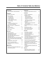
Table of Contents/Table des Matières
Introduction
Oven Description and Specifications 2. . . .
Installation
Delivery and Location 3. . . . . . . . . . . . . . . . .
Oven Assembly 4. . . . . . . . . . . . . . . . . . . . . .
Sanitation Bolts 4. . . . . . . . . . . . . . . . . . . . .
Leg Attachment 5. . . . . . . . . . . . . . . . . . . . .
Caster Assembly 5. . . . . . . . . . . . . . . . . . . .
Double Section Assembly 6. . . . . . . . . . . .
Oven Leveling 6. . . . . . . . . . . . . . . . . . . . . .
Ventilation 7. . . . . . . . . . . . . . . . . . . . . . . . . . .
Canopy Type Exhaust Hood 7. . . . . . . . . .
Direct Flue Arrangement 8. . . . . . . . . . . . .
Utility Connections - Standards and
Codes 9. . . . . . . . . . . . . . . . . . . . . . . . . . . . . . .
Gas Connection 10. . . . . . . . . . . . . . . . . . . . . .
Electrical Connection 13. . . . . . . . . . . . . . . . .
Initial Startup 14. . . . . . . . . . . . . . . . . . . . . . . . .
Operation
Safety Information 15. . . . . . . . . . . . . . . . . . . .
Solid State Manual Control 16. . . . . . . . . . . . .
Solid State Digital Control 17. . . . . . . . . . . . . .
Solid State Digital Control with Core
Temperature Probe 20. . . . . . . . . . . . . . . . . . .
Solid State Digital Control with Humidaire 24
CHĆPro3 (Solid State Programmable Digital
Control) 27. . . . . . . . . . . . . . . . . . . . . . . . . . . . .
Blodgett IQ2T Vision Control 30. . . . . . . . . .
How Cook and Hold Works 40. . . . . . . . . . . .
General Guidelines for Operating
Personnel 41. . . . . . . . . . . . . . . . . . . . . . . . . . . .
Maintenance
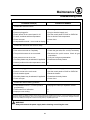
Cleaning and Preventative Maintenance 42.
Troubleshooting Guide 43. . . . . . . . . . . . . . . .
Introduction
Description et Spécifications du Four 44. . . .
Installation
Livraison et Implantation 45. . . . . . . . . . . . . . .
Montage du Four 46. . . . . . . . . . . . . . . . . . . . .
Boulons Sanitation 46. . . . . . . . . . . . . . . . . .
Assemblage des Pieds 47. . . . . . . . . . . . . . .
Montage des Roulettes 47. . . . . . . . . . . . . .
Montage de la Section Double 48. . . . . . . .
Mise à Niveau du Four 48. . . . . . . . . . . . . . .
Ventilation 49. . . . . . . . . . . . . . . . . . . . . . . . . . .
Hotte D'évacuation Type Voûte 49. . . . . . .
En Prise Directe 50. . . . . . . . . . . . . . . . . . . . .
Branchements de Service - Normes et
Codes 51. . . . . . . . . . . . . . . . . . . . . . . . . . . . . . .
Branchement de Gaz 52. . . . . . . . . . . . . . . . .
Raccordement Électrique 55. . . . . . . . . . . . . .
Mise en Marche Initiale 56. . . . . . . . . . . . . . . .
Utilisation
Informations de Sécurité 57. . . . . . . . . . . . . . .
Commandes Standard 58. . . . . . . . . . . . . . . .
Commandes Numériques à
SemiĆConducteurs 60. . . . . . . . . . . . . . . . . . . .
Commande Numérique à SemiĆConducteur
avec Sonde de Température Interne 63. . . .
Commandes Numériques à
SemiĆConducteurs avec Humidaire 68. . . . .
CHĆPro3 (Commande Numérique
Programmable pour SemiĆConducteurs) 72.
Blodgett IQ2T Commande Vision 77. . . . . .
Principe de la Fonction de Cuisson et
Maintien 88. . . . . . . . . . . . . . . . . . . . . . . . . . . . .
Consignes Générales à l'Intention des
Utilasateurs 89. . . . . . . . . . . . . . . . . . . . . . . . . .
Entretien
Nettoyage et Entretien Préventif 90. . . . . . . .
Guide de Détection des Pannes 91. . . . . . . .

Introduction
2
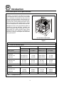
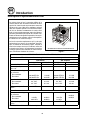
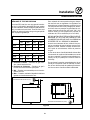
Oven Description and Specifications
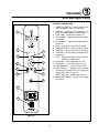
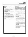
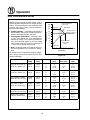
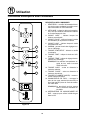
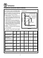
Cooking in a convection oven differs from cooking
in a conventional deck or range oven since heated
air is constantly recirculated over the product by
a fan in an enclosed chamber. The moving air conĆ
tinually strips away the layer of cool air surroundĆ
ing the product, quickly allowing the heat to peneĆ
trate. The result is a high quality product, cooked
at a lower temperature in a shorter amount of time.
Blodgett convection ovens represent the latest adĆ
vancement in energy efficiency, reliability, and
ease of operation. Heat normally lost, is recircuĆ
lated within the cooking chamber before being
vented from the oven: resulting in substantial reĆ
ductions in energy consumption and enhanced
oven performance.
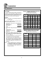
Air Flow Pattern for DFGĆ100 XCEL
Figure 1
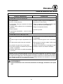
GAS SPECIFICATIONS - DFG1XL/AA
U.S., Canada and General Export
Natural Gas Propane Gas
US Units SI Units US Units SI Units
Heating Value 1000 BTU/cu.ft. 37.3 MJ/m
3
2550 BTU/cu. ft. 95.0 MJ/m
3
Specific Gravity (air=1.0) 0.63 0.63 1.53 1.53
Oven Input
Standard rate
High rate
60,000 BTU/hr
80,000 BTU/hr
17.5 kW
23.5 kW
60,000 BTU/hr
80,000 BTU/hr
17.5 kW
23.5 kW
Manifold Pressure
Standard rate
High rate
2.0" W.C.
3.5" W.C.
5.0 mb
8.7 mb
5.5" W.C.
10.0" W.C.
14.3 mb
25 mb
Main Burner Orifice Size 45 MTD 2.1 mm 55 MTD 1.3 mm
Australia
Oven Input
Standard rate
High rate
0.5 kPa
0.875 kPa
63 MJ/h
84 MJ/h
1.44 kPa
2.5 kPa
63 MJ/h
84 MJ/h
Main Burner Orifice Size 2.1 mm 2.1 mm 55 MTD 1.3 mm
NOTE: * - Multiple Twist Drill

Installation
3
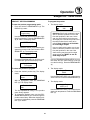
Delivery and Location
DELIVERY AND INSPECTION
All Blodgett ovens are shipped in containers to
prevent damage. Upon delivery of your new oven:
D Inspect the shipping container for external damĆ
age. Any evidence of damage should be noted
on the delivery receipt which must be signed by
the driver.
D Uncrate the oven and check for internal damĆ
age. Carriers will accept claims for concealed
damage if notified within fifteen days of delivery
and the shipping container is retained for inĆ
spection.
The Blodgett Oven Company cannot assume
responsibility for loss or damage suffered in
transit. The carrier assumed full responsibility
for delivery in good order when the shipment
was accepted. We are, however, prepared to
assist you if filing a claim is necessary.
OVEN LOCATION
The well planned and proper placement of your
oven will result in long term operator convenience
and satisfactory performance.
The following clearances must be maintained beĆ
tween the oven and any combustible or nonĆcomĆ
bustible construction.
DFG100 XCEL
D Oven body right side - 0" (0cm)
D Oven body left side - 0" (0cm)
D Oven body back - 0" (0cm)
D Oven body bottom - 6" (15cm)
The following clearances must be available for serĆ
vicing.
D Oven body sides - 12" (30cm)
D Oven body back - 12" (30cm)
NOTE: On gas models, routine servicing can usuĆ
ally be accomplished within the limited
movement provided by the gas hose reĆ
straint. If the oven needs to be moved furĆ
ther from the wall, the gas must first be
turned off and disconnected from the oven
before removing the restraint. Reconnect
the restraint after the oven has been reĆ
turned to its normal position.
It is essential that an adequate air supply to the
oven be maintained to provide a sufficient flow of
combustion and ventilation air.
D Place the oven in an area that is free of drafts.
D Keep the oven area free and clear of all combusĆ
tibles such as paper, cardboard, and flammable
liquids and solvents.
D A clearance of 6" is required on the bottom and
sides of the unit for cleaning. Do not place the
oven on a curb base or seal to a wall.
D The location must provide adequate clearance
for the air opening into the combustion chamĆ
ber.
Before making any utility connections to this oven,
check the rating plate to be sure the oven specifiĆ
cations are compatible with the gas and electrical
services supplied for the oven.
1. The rating plate is located inside the combusĆ
tion compartment.

Installation
4
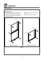
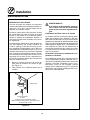
Oven Assembly
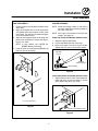
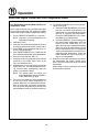
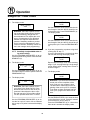
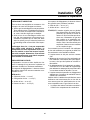
SANITATION BOLTS
These bolts are required to block any exposed
hole on the back of an oven. This includes:
D any unit, single or stacked, without a back panel.
D any holes in stacked units not used for mountĆ
ing stacking brackets.
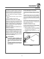
1. Locate the 5/16" bolts that were shipped with
the oven.
2. Install the bolts as shown in Figure 2.
Double Stacked Units Units without Back Panels
Figure 2

Installation
5
Oven Assembly
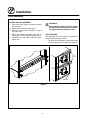
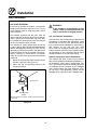
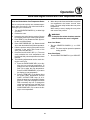
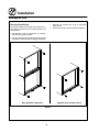
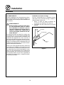
LEG ATTACHMENT
1. Push the oven onto a lift with the bottom of the
oven down.
2. Align the threaded stud in each leg with the
nut located inside each bottom corner of the
oven frame. Turn the legs clockwise and tightĆ
en to the nearest full turn.
3. Align the two leg plate holes in each leg with
those in the oven bottom. Secure each leg usĆ
ing two 1/2" bolts.
NOTE: If using casters see CASTER ASĆ
SEMBLY before proceeding.
4. Level the oven by screwing the adjustable leg
feet in or out as necessary.
6" (15 cm) Legs Shown
Figure 3
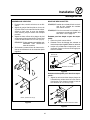
CASTER ASSEMBLY
NOTE: Install the locking casters on the front of
the oven. Install the nonĆlocking casters on
the back of the oven.
NOTE: Use a gas hose restraint on all units with
casters. See page 12.
Casters for Single and Double Stacked Ovens:
1. Attach the legs as described.
2. Pry the adjustable feet out of the legs.
3. Insert one caster into each leg as shown.
Tighten the lock nuts to secure the casters.
Adjustable
Leg Foot
Caster Assembly
Gas Hose
Restraint Bracket
Figure 4
Low Profile Casters for Double Stacked Ovens:
1. Align the three holes in each caster assembly
plate with those in the oven bottom. Secure
each caster using three 1/2" bolts.
Gas Hose Restraint Bracket
Figure 5

Installation
6
Oven Assembly
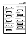
DOUBLE SECTION ASSEMBLY
1. Secure the short legs to the bottom sections
as described.
2. Attach lower flue box to lower oven.
3. Place the upper section in position on top of
the lower oven.
4. Attach the stacking brackets using the reĆ
maining 5/16" bolts shipped with the ovens.
5. Install flue riser and attach upper flue box to
upper oven.
WARNING!!
When stacking ovens be sure to remove
the single oven flue boxes prior to attachĆ
ing upper and lower boxes and riser.
OVEN LEVELING
After assembly, the oven should be leveled and
moved to the operating location.
1. The oven can be leveled by adjusting the feet
or casters located on the bottom of each leg.
Flue Riser
Flue
Boxes
Figure 6

Installation
7
Ventilation
On gas models the installation of a proper ventilaĆ
tion system cannot be over emphasized. This sysĆ
tem removes unwanted vapors and products of
combustion from the operating area.
This oven may be vented using either:
D A mechanically driven, canopy type, exhaust
hood, or
D A direct flue arrangement.
U.S. and Canadian installations
Refer to your local ventilation codes. In the abĆ
sence of local codes, refer to the National ventilaĆ
tion code titled, Standard for the Installation of
Equipment for the Removal of Smoke and Grease
Laden Vapors from Commercial Cooking EquipĆ
ment", NFPAĆ96ĆLatest Edition.
Australia and general export installations
Installation must conform with Local and National
installation standards. Local installation codes
and/or requirements may vary. If you have any
questions regarding the proper installation and/or
operation of your Blodgett oven, please contact
your local distributor. If you do not have a local disĆ
tributor, please call the Blodgett Oven Company at
0011Ć802Ć860Ć3700.
WARNING:
Failure to properly vent the oven can be
hazardous to the health of the operator
and may result in operational problems,
unsatisfactory baking and possible damĆ
age to the equipment.
Damage sustained as a direct result of imĆ
proper ventilation will not be covered by
the manufacturer's warranty.
CANOPY TYPE EXHAUST HOOD
A mechanically driven, canopy type exhaust hood
is the preferred method of ventilation.
The hood should be sized to completely cover the
equipment plus an overhang of at least 6" (15 cm)
on all sides not adjacent to a wall. The distance
from the floor to the lower edge of the hood should
not exceed 7' (2.1m).
The total makeup and exhaust air requirements for
hood capacity should be approximately 30 CFM
(.85 m
3
) for each oven section.
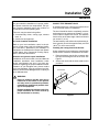
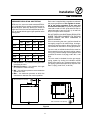
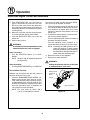
Installing the canopy hood draft diverter
Ovens ordered for hood venting are supplied with
a draft diverter. Install the draft diverter as follows:
1. Place the diverter over the flue connector with
the open area facing the front of the oven. See
Figure 7.
2. Secure both ends with the sheet metal screws
provided.
Front of
Oven
Draft Diverter
Figure 7

Installation
8
Ventilation
DIRECT FLUE ARRANGEMENT
When the installation of a mechanically driven exĆ
haust hood is impractical the oven may be vented
by a direct flue arrangement.
WARNING!!
It is essential that the direct flue be
installed as follows. Incorrect installation
will result in unsatisfactory baking and
oven damage.
The flue must be class B or better with a diameter
of 6" (15 cm) for single ovens and 8" (20 cm) for
double stacked ovens. The height of the flue
should rise 6Ć8 ft (2Ć2.5 m) above the roof of the
building or any proximate structure. Never direct
vent the oven into a hood. The flue should be
capped with a UL Listed type vent cap to isolate
the unit from external environmental conditions.
The direct vent cannot replace air consumed and
vented by the oven. Provisions must be made to
supply the room with sufficient makeĆup air. Total
makeĆup air requirements for each oven section
should be approximately 30 CFM (.85 m
3
) per secĆ
tion. To increase the supply air entering the room,
a ventilation expert should be consulted.
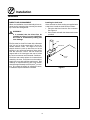
Installing the draft hood
Ovens ordered for direct venting are supplied with
a draft hood. Install the draft hood as follows:
1. Place the draft hood over the flue connector.
See Figure 8.
2. Secure both ends with the sheet metal screws
provided.
Front of
Oven
Draft Hood
Flue
Figure 8

Installation
9
Utility Connections - Standards and Codes
THE INSTALLATION INSTRUCTIONS CONĆ
TAINED HEREIN ARE FOR THE USE OF QUALIĆ
FIED INSTALLATION AND SERVICE PERSONNEL
ONLY. INSTALLATION OR SERVICE BY OTHER
THAN QUALIFIED PERSONNEL MAY RESULT IN
DAMAGE TO THE OVEN AND/OR INJURY TO
THE OPERATOR.
Qualified installation personnel are individuals, a
firm, a corporation, or a company which either in
person or through a representative are engaged
in, and responsible for:
D the installation or replacement of gas piping
and the connection, installation, repair or servĆ
icing of equipment.
D the installation of electrical wiring from the elecĆ
tric meter, main control box or service outlet to
the electric appliance.
Qualified installation personnel must be experiĆ
enced in such work, familiar with all precautions
required, and have complied with all requirements
of state or local authorities having jurisdiction.
U.S. and Canadian installations
The installation must conform with local codes, or
in the absence of local codes, with the National
Fuel Gas Code, ANSI Z223.1/NFPA 54, or the NatuĆ
ral Gas and Propane Installation Code, CSA
B149.1, as applicable.
Installation must conform with local codes, or in
the absence of local codes, with the National ElecĆ
trical Code, ANSI/NFPA 70-Latest Edition and/or
Canadian National Electric Code C22.1 as applicaĆ
ble.
Appliance is to be installed with backflow prevenĆ
tion in accordance with applicable federal, provĆ
ince and local codes.
Australia and general export installations
Installation must conform with Local and National
installation standards. Local installation codes
and/or requirements may vary. If you have any
questions regarding the proper installation and/or
operation of your Blodgett oven, please contact
your local distributor. If you do not have a local disĆ
tributor, please call the Blodgett Oven Company at
0011Ć802Ć860Ć3700.

Installation
10
Gas Connection
GAS PIPING
A properly sized gas supply system is essential for
maximum oven performance. Piping should be
sized to provide a supply of gas sufficient to meet
the maximum demand of all appliances on the line
without loss of pressure at the equipment.
Example:
NOTE: BTU values in the following example are
for natural gas.
You purchase a DFGĆ100 XCEL convection oven to
add to your existing cook line.
1. Add the BTU rating of your current appliances.
Pitco Fryer 120,000 BTU
6 Burner Range 60,000 BTU
Deck Oven 50,000 BTU
Total 230,000 BTU
2. Add the BTU rating of the new oven to the toĆ
tal.
Previous Total 230,000 BTU
DFGĆ100 XCEL (high rate) 80,000 BTU
New Total 310,000 BTU
3. Measure the distance from the gas meter to
the cook line. This is the pipe length. Let's say
the pipe length is 40' (12.2 m) and the pipe
size is 1" (2.54 cm).
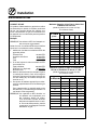
4. Use the appropriate table to determine the toĆ
tal capacity of your current gas piping.
The total capacity for this example is 320,000
BTU. Since the total required gas pressure,
310,000 BTU is less than 320,000 BTU, the
current gas piping will not have to be inĆ
creased.
NOTE: The BTU capacities given in the tables are
for straight pipe lengths only. Any elbows
or other fittings will decrease pipe capaciĆ
ties. Contact your local gas supplier if you
have any questions.
Maximum Capacity of Iron Pipe in Cubic Feet
of Natural Gas Per Hour
(Pressure drop of 0.5 Inch W.C.)
Pipe
L th (ft)
Nominal Size, Inches
p
Length (ft)
3/4" 1" 1Ć1/4" 1Ć1/2" 2"
10 360 680 1400 2100 3950
20 250 465 950 1460 2750
30 200 375 770 1180 2200
40 170 320 660 990 1900
50 151 285 580 900 1680
60 138 260 530 810 1520
70 125 240 490 750 1400
80 118 220 460 690 1300
90 110 205 430 650 1220
100 103 195 400 620 1150
From the National Fuel Gas Code Part 10 Table 10Ć2
Maximum Capacity of Pipe in Thousands of
BTU/hr of Undiluted L.P. Gas at 11" W.C.
(Pressure drop of 0.5 Inch W.C.)
Pipe Length
(ft)
Outside Diameter, Inches
pg
(ft)
3/4" 1" 1Ć1/2"
10 608 1146 3525
20 418 788 2423
30 336 632 1946
40 287 541 1665
50 255 480 1476
60 231 435 1337
70 215 404 1241
80 198 372 1144
90 187 351 1079
100 175 330 1014
From the National Fuel Gas Code Part 10 Table 10Ć15

Installation
11
Gas Connection
PRESSURE REGULATION AND TESTING
DFGĆ100 XCEL ovens are rated at 60,000 BTU/Hr.
(17.5 kW) (63 MJ) per section at standard rate or
80,000 BTU/Hr. (23.5 kW) (84 MJ) per section at
high rate. Each oven has been adjusted at the facĆ
tory to operate with the type of gas specified on the
rating plate.
Inlet Pressure
Natural Propane
Min Max Min Max
W.C. 7.0" 10.5" 11.0" 13.0"
kPa 1.742 2.61 2.74 3.23
Manifold Pressure
Natural Propane
W.C. 2.0" 3.5" 5.5" 10.0"
kPa 0.50 .87 1.37 2.49
D Inlet Pressure - the pressure of the gas before
it reaches the oven.
D Manifold Pressure - the pressure of the gas
as it enters the main burner(s).
D Min - the minimum pressure recommended to
operate the oven.
D Max - the maximum pressure at which the
manufacturer warrants the oven's operation.
Each oven is supplied with a regulator to maintain
the proper gas pressure. The regulator is essenĆ
tial to the proper operation of the oven and
should not be removed. It is preset to provide the
oven with 2.0 and 3.5" W.C. (0.50 and 0.87 kPa) for
natural gas and 5.5 and 10.0" W.C. (1.37 and 2.50
kPa) for Propane at the manifold.
DO NOT INSTALL AN ADDITIONAL REGULATOR
WHERE THE OVEN CONNECTS TO THE GAS
SUPPLY UNLESS THE INLET PRESSURE IS
ABOVE MAXIMUM.
Prior to connecting the oven, gas lines should be
thoroughly purged of all metal filings, shavings,
pipe dope, and other debris. After connection, the
oven should be checked for correct gas pressure.
The oven and its individual shutoff valve must be
disconnected from the gas supply piping system
during any pressure testing of that system at test
pressures in excess of 1/2 psig (13.85" W.C., 3.45
kPa).
The oven must be isolated from the gas supply
piping system by closing its individual manual
shutoff valve during any pressure testing of the
gas piping system at test pressures equal or less
than 1/2 psig (13.85" W.C., 3.45 kPa).
Gas Connection 3" (76 mm)
Gas Connection 3.75" (86 mm)
Figure 9

Installation
12
Gas Connection
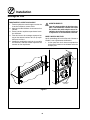
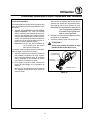
GAS HOSE RESTRAINT
If the oven is mounted on casters, a commercial
flexible connector with a minimum of 3/4" (1.9 cm)
inside diameter must be used along with a quick
connect device.
The restraint, supplied with the oven, must be
used to limit the movement of the unit so that no
strain is placed upon the flexible connector. With
the restraint fully stretched the connector should
be easy to install and quick connect.
The restraint (ie: heavy gauge cable) should be
1,000 lb. (453 kg) test load and should be attached
without damaging the building. DO NOT use the
gas piping or electrical conduit for the attachment
of the permanent end of the restraint! Use anchor
bolts in concrete or cement block. On wooden
walls, drive hi test wood lag screws into the studs
of the wall.
1. Mount the supplied bracket to the leg bolt just
below the gas inlet. See Figure 10.
2. Attach the clip on restraining cable to the
mounting bracket.
Restraint Cable
Bracket
Back of Oven
Double stacked unit shown. Use the same procedure for
single units.
Figure 10
WARNING!!
If the restraint is disconnected for any
reason it must be reconnected when the
oven is returned to its original position.
U.S. and Canadian installations
The connector must comply with the Standard for
Connectors for Movable Gas Appliances, ANSI
Z21.69VCSA 6.16 and a quick disconnect device
that complies with the Standard for QuickĆDisconĆ
nect Devices for Use with Gas Fuel, ANSI
Z21.41VCSA 6.9. Adequate means must be proĆ
vided to limit the movement of the appliance withĆ
out depending on the connection and the quick
disconnect device or its associated piping.
Australia and general export installations
The restraint and quick connect must conform
with Local and National installation standards. LoĆ
cal installation codes and/or requirements may
vary. If you have any questions regarding the propĆ
er installation and/or operation of your Blodgett
oven, please contact your local distributor. If you
do not have a local distributor, please call the
Blodgett Oven Company at 0011Ć802Ć860Ć3700.

Installation
13
Electrical Connection
Wiring diagrams are located in the control
compartment and on the back of the oven.
This oven is supplied for connection to 115 volt
grounded circuits. The electric motor, indicator
lights and related switches are connected through
the 6' electric supply cord found at the rear of the
oven.
WARNING!!
This appliance is equipped with three
prong grounding type plug for your
protection against shock hazard and
should be plugged directly into a properly
grounded three prong receptacle. DO
NOT cut or remove the grounding prong
from this plug.
THE BLODGETT OVEN COMPANY CANNOT ASĆ
SUME RESPONSIBILITY FOR LOSS OR DAMAGE
SUFFERED AS A RESULT OF IMPROPER INSTALĆ
LATION.
ELECTRICAL SPECIFICATIONS
Hz Volts Phase Amps Electrical Connection
(minimum size)
U.S. and Canadian Installations
60 115 1 10 Cord set provided
Australia and General Export Installations
50 220Ć240 1 5 Size per local code

Installation
14
Initial Startup
The following is a checkĆlist to be completed by
qualified personnel prior to turning on the
appliance for the first time.
j Open the manual shutĆoff valve at the rear of
the oven.
j Remove the control panel and combustion
cover.
j Be sure the gas on/off switch on the front panĆ
el is in the on position.
j Turn the selector switch to High Fan, 80,000
BTU, and the thermostat to 550_F (288_C).
The oven main burner lights, and the Oven Ready
Light comes on. With the main burner on, check
the following.
j Verify there are no gas leaks, by checking all
gas connections with a soapy water solution.
j Verify that the inlet pressure is correct. The inĆ
let pressure can be checked at the pressure
tap located on the combination valve's inlet
side.
j Verify that the manifold pressure is correct.
The manifold pressure can be checked at the
pressure tap located on the manifold. Check
pressure at both 80,000 BTU and 60,000 BTU.
j If the pressure readings are not set correctly,
adjust accordingly.
j FIRST TIME ONLY BREAKĆIN PROCEDURES
a.) Set burner rate to 60,000 BTU.
b.) Turn oven on high fan and adjust thermoĆ
stat to 350°F (177°C). Allow oven to heat
soak for one hour.
c.) Adjust thermostat to 550°F (288°C). After
reaching setpoint, set burner rate to
80,000 BTU. Allow oven to heat soak until
all residual smoke and fumes have
stopped.
WARNING
The break in procedure burns off excess
oils present in the metals during fabricaĆ
tion. Smoke may be produced. Proper
ventilation is required.
ADJUSTMENTS ASSOCIATED WITH INITIAL
INSTALLATION
Each oven, and its component parts, have been
thoroughly tested and inspected prior to shipĆ
ment. However, it is often necessary to further
test or adjust the oven as part of a normal and
proper installation. These adjustments are the
responsibility of the installer, or dealer. Since
these adjustments are not considered defects
in material or workmanship, they are not covĆ
ered by the Original Equipment Warranty. They
include, but are not limited to:
D calibration of the thermostat
D adjustment of the doors
D burner adjustments
D leveling
D testing of gas pressure
D tightening of fasteners.
No installation should be considered complete
without proper inspection, and if necessary,
adjustment by qualified installation or service
personnel.

Operation
15
Safety Information
THE INFORMATION CONTAINED IN THIS SECĆ
TION IS PROVIDED FOR THE USE OF QUALIFIED
OPERATING PERSONNEL. QUALIFIED OPERATĆ
ING PERSONNEL ARE THOSE WHO HAVE
CAREFULLY READ THE INFORMATION CONĆ
TAINED IN THIS MANUAL, ARE FAMILIAR WITH
THE FUNCTIONS OF THE OVEN AND/OR HAVE
HAD PREVIOUS EXPERIENCE WITH THE OPĆ
ERATION OF THE EQUIPMENT DESCRIBED. ADĆ
HERENCE TO THE PROCEDURES RECOMĆ
MENDED HEREIN WILL ASSURE THE
ACHIEVEMENT OF OPTIMUM PERFORMANCE
AND LONG, TROUBLEĆFREE SERVICE.
Please take the time to read the following safety
and operating instructions. They are the key to the
successful operation of your Blodgett conveyor
oven.
SAFETY TIPS
For your safety read before operating
What to do if you smell gas:
D DO NOT try to light any appliance.
D DO NOT touch any electrical switches.
D Use an exterior phone to call your gas supplier
immediately.
D If you cannot reach your gas supplier, call the
fire department.
What to do in the event of a power failure:
D Turn all switches to off.
D DO NOT attempt to operate the oven until the
power is restored.
NOTE: In the event of a shutĆdown of any kind, alĆ
low a five (5) minute shut off period before
attempting to restart the oven.
General safety tips:
D DO NOT use tools to turn off the gas control. If
the gas cannot be turned off manually do not try
to repair it. Call a qualified service technician.
D If the oven needs to be moved for any reason,
the gas must be turned off and disconnected
from the unit before removing the restraint
cable. Reconnect the restraint after the oven
has been returned to its original location.
D DO NOT remove the control panel cover unless
the oven is unplugged.

Operation
16
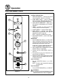
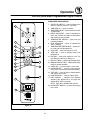
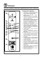
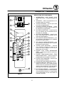
Solid State Manual Control
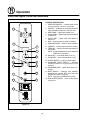
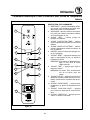
1
2
3
4
5
6
7
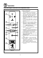
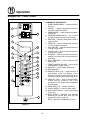
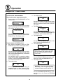
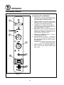
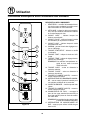
Figure 11
CONTROL DESCRIPTION
1. SELECTOR SWITCH - controls power to the
oven for high fan, low fan or cool down.
2. OVEN READY LIGHT - when lit indicates
burner operation. When the light goes out the
oven has reached operating temperature.
3. SOLID STATE THERMOSTAT - allows an infiĆ
nite selection of temperatures from 150Ć550_F
(66Ć288_C).
4. TIMER - activates an electric buzzer that
sounds when the cook time expires.
5. LIGHTS SWITCH - controls interior lights.
6. RATE SWITCH - switches oven between
standard rate (60,000 BTU) and high rate
(80,000 BTU) while in high fan.
NOTE: High rate is disabled with low fan.
7. GAS ON/OFF SWITCH - press to shut off gas
to the oven.
OPERATION
1. Turn the SELECTOR Switch (1) to either HIGH
FAN or LOW FAN. The blower and control comĆ
partment cooling fan operate and are controlled
automatically by the action of the doors.
If high fan is chosen, high rate may be seĆ
lected by toggling the RATE SWITCH (6).
2. Set the SOLID STATE THERMOSTAT (3) to the
desired setting or temperature.
3. Preheat until the OVEN READY LIGHT (2)
goes out.
4. Load product into the oven. Determine cook
time and set the TIMER (4).
5. When the buzzer sounds, remove the product
from the oven. Turn the TIMER knob (4) to OFF
to silence the buzzer.
Oven Cool Down:
1. Turn the SELECTOR Switch (1) to COOL
DOWN.
NOTE: The doors may be opened to speed the
cooling process.
Oven Shut Down:
1. Turn the SELECTOR SWITCH (1) to OVEN OFF.
WARNING!!
A complete five minute shutdown must be
observed before the oven is relighted.
La page est en cours de chargement...
La page est en cours de chargement...
La page est en cours de chargement...
La page est en cours de chargement...
La page est en cours de chargement...
La page est en cours de chargement...
La page est en cours de chargement...
La page est en cours de chargement...
La page est en cours de chargement...
La page est en cours de chargement...
La page est en cours de chargement...
La page est en cours de chargement...
La page est en cours de chargement...
La page est en cours de chargement...
La page est en cours de chargement...
La page est en cours de chargement...
La page est en cours de chargement...
La page est en cours de chargement...
La page est en cours de chargement...
La page est en cours de chargement...
La page est en cours de chargement...
La page est en cours de chargement...
La page est en cours de chargement...
La page est en cours de chargement...
La page est en cours de chargement...
La page est en cours de chargement...
La page est en cours de chargement...
La page est en cours de chargement...
La page est en cours de chargement...
La page est en cours de chargement...
La page est en cours de chargement...
La page est en cours de chargement...
La page est en cours de chargement...
La page est en cours de chargement...
La page est en cours de chargement...
La page est en cours de chargement...
La page est en cours de chargement...
La page est en cours de chargement...
La page est en cours de chargement...
La page est en cours de chargement...
La page est en cours de chargement...
La page est en cours de chargement...
La page est en cours de chargement...
La page est en cours de chargement...
La page est en cours de chargement...
La page est en cours de chargement...
La page est en cours de chargement...
La page est en cours de chargement...
La page est en cours de chargement...
La page est en cours de chargement...
La page est en cours de chargement...
La page est en cours de chargement...
La page est en cours de chargement...
La page est en cours de chargement...
La page est en cours de chargement...
La page est en cours de chargement...
La page est en cours de chargement...
La page est en cours de chargement...
La page est en cours de chargement...
La page est en cours de chargement...
La page est en cours de chargement...
La page est en cours de chargement...
La page est en cours de chargement...
La page est en cours de chargement...
La page est en cours de chargement...
La page est en cours de chargement...
La page est en cours de chargement...
La page est en cours de chargement...
La page est en cours de chargement...
La page est en cours de chargement...
La page est en cours de chargement...
La page est en cours de chargement...
La page est en cours de chargement...
La page est en cours de chargement...
La page est en cours de chargement...
La page est en cours de chargement...
La page est en cours de chargement...
-
 1
1
-
 2
2
-
 3
3
-
 4
4
-
 5
5
-
 6
6
-
 7
7
-
 8
8
-
 9
9
-
 10
10
-
 11
11
-
 12
12
-
 13
13
-
 14
14
-
 15
15
-
 16
16
-
 17
17
-
 18
18
-
 19
19
-
 20
20
-
 21
21
-
 22
22
-
 23
23
-
 24
24
-
 25
25
-
 26
26
-
 27
27
-
 28
28
-
 29
29
-
 30
30
-
 31
31
-
 32
32
-
 33
33
-
 34
34
-
 35
35
-
 36
36
-
 37
37
-
 38
38
-
 39
39
-
 40
40
-
 41
41
-
 42
42
-
 43
43
-
 44
44
-
 45
45
-
 46
46
-
 47
47
-
 48
48
-
 49
49
-
 50
50
-
 51
51
-
 52
52
-
 53
53
-
 54
54
-
 55
55
-
 56
56
-
 57
57
-
 58
58
-
 59
59
-
 60
60
-
 61
61
-
 62
62
-
 63
63
-
 64
64
-
 65
65
-
 66
66
-
 67
67
-
 68
68
-
 69
69
-
 70
70
-
 71
71
-
 72
72
-
 73
73
-
 74
74
-
 75
75
-
 76
76
-
 77
77
-
 78
78
-
 79
79
-
 80
80
-
 81
81
-
 82
82
-
 83
83
-
 84
84
-
 85
85
-
 86
86
-
 87
87
-
 88
88
-
 89
89
-
 90
90
-
 91
91
-
 92
92
-
 93
93
-
 94
94
-
 95
95
-
 96
96
-
 97
97


Blodgett DFG-100 XCel spécification
- Catégorie
- Cuisinières
- Taper
- spécification
- Ce manuel convient également à
dans d''autres langues
- English: Blodgett DFG-100 XCel Specification
Documents connexes
-
Blodgett DFG-200 Mode d'emploi
-
-
-
-
-
Blodgett ZEPHAIRE-G Mode d'emploi
-
-
-
-