Lincoln Electric EASY-MIG 180 Le manuel du propriétaire
- Catégorie
- Système de soudage
- Taper
- Le manuel du propriétaire

• Sales and Service through Subsidiaries and Distributors Worldwide •
Cleveland, Ohio 44117-1199 U.S.A. TEL: 216.481.8100 FAX: 216.486.1751 WEB SITE: www.lincolnelectric.com
• World's Leader in Welding and Cutting Products •
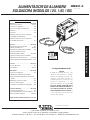
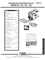
OPERATOR’S MANUAL
MANUAL DE OPERACIÓN
MANUEL DE L’OPÉRATEUR
ISO 9001
CERTIFICATE NUMBER: 30273
Designed and Manufactured Under aI
Quality Program Certified byI
ABS Quality Evaluations, Inc.I
to ISO 9001 Requirements.
QMS
ANSI RAB
Copyright © Lincoln Global Inc.
WIRE FEEDER
WELDER (125, 140, 180 MODELS)
IM891-C
January, 2009
For use with machines having Code Numbers: 11173 thru 11506, 11550
TABLE OF CONTENTS
Installation ...........................Section A
Technical Specifications ...................A-1,A-2
SafetyPrecautions...........................A-2
Location .................................A-2
Stacking .................................A-2
Tilting ...................................A-2
Identify and Locate Components for 180 Amp
and140AmpUnits .........................A-3
Identify and Locate Components for 125 Amp
FluxCoreUnit.............................A-3
Operation ............................Section B
Safety and Product Description .................B-1
ControlsandSettings.....................B-2,B-3
DriveRollandWireGuidesTable ...............B-4
Setting Up and Making a Flux-Cored Weld .B-4 thru B-6
Setting Up and Making a MIG Weld and
InstallShieldingGas ................B-7thruB-10
Setting Up and Making a Aluminum Weld ........B-11
Accessories . . . .......................Section C
Optional Accessories .........................C-1
Utility Carts ............................C-2,C-3
Maintenance..........................Section D
SafetyPrecautions ..........................D-1
Wire Feed Compartment, Fan Motor, Wire Reel
Maintenance ..............................D-1
GunAndCableMaintenance ..................D-2
OverloadProtection..........................D-2
Component Replacement Procedures ...........D-2
Troubleshooting ......................Section E
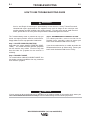
SafetyPrecautions...........................E-1
How to Use Troubleshooting Guide ..............E-1
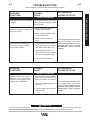
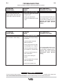
Troubleshooting Guide .................E-2thruE-3
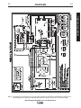
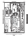
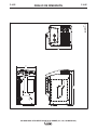
Wiring Diagram and Dimension Print .....Section F
Safety Depends on You
Lincoln arc welding and cutting
equipment is designed and built
with safety in mind. However, your
overall safety can be increased by
proper installation ... and thought-
ful operation on your part. DO
NOT INSTALL, OPERATE OR
REPAIR THIS EQUIPMENT
WITHOUT READING THIS
MANUAL AND THE SAFETY
PRECAUTIONS CONTAINED
THROUGHOUT. And, most
importantly, think before you act
and be careful.
RETURN TO MAIN MENU

i
SAFETY
i
FOR ENGINE
powered equipment.
1.a. Turn the engine off before troubleshooting and maintenance
work unless the maintenance work requires it to be running.
____________________________________________________
1.b. Operate engines in open, well-ventilated
areas or vent the engine exhaust fumes
outdoors.
____________________________________________________
1.c. Do not add the fuel near an open flame
welding arc or when the engine is running.
Stop the engine and allow it to cool before
refueling to prevent spilled fuel from vaporiz-
ing on contact with hot engine parts and
igniting. Do not spill fuel when filling tank. If
fuel is spilled, wipe it up and do not start
engine until fumes have been eliminated.
____________________________________________________
1.d. Keep all equipment safety guards, covers and devices in
position and in good repair.Keep hands, hair, clothing and
tools away from V-belts, gears, fans and all other moving
parts when starting, operating or repairing equipment.
____________________________________________________
1.e. In some cases it may be necessary to remove safety
guards to perform required maintenance. Remove
guards only when necessary and replace them when the
maintenance requiring their removal is complete.
Always use the greatest care when working near moving
parts.
___________________________________________________
1.f. Do not put your hands near the engine fan.
Do not attempt to override the governor or
idler by pushing on the throttle control rods
while the engine is running.
___________________________________________________
1.g. To prevent accidentally starting gasoline engines while
turning the engine or welding generator during maintenance
work, disconnect the spark plug wires, distributor cap or
magneto wire as appropriate.
ARC WELDING CAN BE HAZARDOUS. PROTECT YOURSELF AND OTHERS FROM POSSIBLE SERIOUS INJURY OR DEATH.
KEEP CHILDREN AWAY. PACEMAKER WEARERS SHOULD CONSULT WITH THEIR DOCTOR BEFORE OPERATING.
Read and understand the following safety highlights. For additional safety information, it is strongly recommended that you
purchase a copy of “Safety in Welding & Cutting - ANSI Standard Z49.1” from the American Welding Society, P.O. Box
351040, Miami, Florida 33135 or CSA Standard W117.2-1974. A Free copy of “Arc Welding Safety” booklet E205 is available
from the Lincoln Electric Company, 22801 St. Clair Avenue, Cleveland, Ohio 44117-1199.
BE SURE THAT ALL INSTALLATION, OPERATION, MAINTENANCE AND REPAIR PROCEDURES ARE
PERFORMED ONLY BY QUALIFIED INDIVIDUALS.
WARNING
Mar ‘95
ELECTRIC AND
MAGNETIC FIELDS
may be dangerous
2.a. Electric current flowing through any conductor causes
localized Electric and Magnetic Fields (EMF). Welding
current creates EMF fields around welding cables and
welding machines
2.b. EMF fields may interfere with some pacemakers, and
welders having a pacemaker should consult their physician
before welding.
2.c. Exposure to EMF fields in welding may have other health
effects which are now not known.
2.d. All welders should use the following procedures in order to
minimize exposure to EMF fields from the welding circuit:
2.d.1.
Route the electrode and work cables together - Secure
them with tape when possible.
2.d.2. Never coil the electrode lead around your body.
2.d.3. Do not place your body between the electrode and
work cables. If the electrode cable is on your right
side, the work cable should also be on your right side.
2.d.4. Connect the work cable to the workpiece as close as
possible to the area being welded.
2.d.5. Do not work next to welding power source.
1.h. To avoid scalding, do not remove the
radiator pressure cap when the engine is
hot.
CALIFORNIA PROPOSITION 65 WARNINGS
Diesel engine exhaust and some of its constituents
are known to the State of California to cause can-
cer, birth defects, and other reproductive harm.
The engine exhaust from this product contains
chemicals known to the State of California to cause
cancer, birth defects, or other reproductive harm.
The Above For Diesel Engines The Above For Gasoline Engines

ii
SAFETY
ii
ARC RAYS can burn.
4.a. Use a shield with the proper filter and cover
plates to protect your eyes from sparks and
the rays of the arc when welding or observing
open arc welding. Headshield and filter lens
should conform to ANSI Z87. I standards.
4.b. Use suitable clothing made from durable flame-resistant
material to protect your skin and that of your helpers from
the arc rays.
4.c. Protect other nearby personnel with suitable, non-flammable
screening and/or warn them not to watch the arc nor expose
themselves to the arc rays or to hot spatter or metal.
ELECTRIC SHOCK can
kill.
3.a. The electrode and work (or ground) circuits
are electrically “hot” when the welder is on.
Do not touch these “hot” parts with your bare
skin or wet clothing. Wear dry, hole-free
gloves to insulate hands.
3.b. Insulate yourself from work and ground using dry insulation.
Make certain the insulation is large enough to cover your full
area of physical contact with work and ground.
In addition to the normal safety precautions, if welding
must be performed under electrically hazardous
conditions (in damp locations or while wearing wet
clothing; on metal structures such as floors, gratings or
scaffolds; when in cramped positions such as sitting,
kneeling or lying, if there is a high risk of unavoidable or
accidental contact with the workpiece or ground) use
the following equipment:
• Semiautomatic DC Constant Voltage (Wire) Welder.
• DC Manual (Stick) Welder.
• AC Welder with Reduced Voltage Control.
3.c. In semiautomatic or automatic wire welding, the electrode,
electrode reel, welding head, nozzle or semiautomatic
welding gun are also electrically “hot”.
3.d. Always be sure the work cable makes a good electrical
connection with the metal being welded. The connection
should be as close as possible to the area being welded.
3.e. Ground the work or metal to be welded to a good electrical
(earth) ground.
3.f.
Maintain the electrode holder, work clamp, welding cable and
welding machine in good, safe operating condition. Replace
damaged insulation.
3.g. Never dip the electrode in water for cooling.
3.h. Never simultaneously touch electrically “hot” parts of
electrode holders connected to two welders because voltage
between the two can be the total of the open circuit voltage
of both welders.
3.i. When working above floor level, use a safety belt to protect
yourself from a fall should you get a shock.
3.j. Also see Items 6.c. and 8.
FUMES AND GASES
can be dangerous.
5.a. Welding may produce fumes and gases
hazardous to health. Avoid breathing these
fumes and gases.When welding, keep
your head out of the fume. Use enough
ventilation and/or exhaust at the arc to keep
fumes and gases away from the breathing zone. When
welding with electrodes which require special
ventilation such as stainless or hard facing (see
instructions on container or MSDS) or on lead or
cadmium plated steel and other metals or coatings
which produce highly toxic fumes, keep exposure as
low as possible and below Threshold Limit Values (TLV)
using local exhaust or mechanical ventilation. In
confined spaces or in some circumstances, outdoors, a
respirator may be required. Additional precautions are
also required when welding on galvanized steel.
5. b. The operation of welding fume control equipment is affected
by various factors including proper use and positioning of
the equipment, maintenance of the equipment and the spe-
cific welding procedure and application involved. Worker
exposure level should be checked upon installation and
periodically thereafter to be certain it is within applicable
OSHA PEL and ACGIH TLV limits.
5.c.
Do not weld in locations near chlorinated hydrocarbon
vapors
coming from degreasing, cleaning or spraying operations.
The heat and rays of the arc can react with solvent vapors
to
form phosgene, a highly toxic gas, and other irritating prod-
ucts.
5.d. Shielding gases used for arc welding can displace air and
cause injury or death. Always use enough ventilation,
especially in confined areas, to insure breathing air is safe.
5.e. Read and understand the manufacturer’s instructions for this
equipment and the consumables to be used, including the
material safety data sheet (MSDS) and follow your
employer’s safety practices. MSDS forms are available from
your welding distributor or from the manufacturer.
5.f. Also see item 1.b.
AUG 06
OPERATOR’S MANUAL

iii
SAFETY
iii
FOR ELECTRICALLY
powered equipment.
8.a. Turn off input power using the disconnect
switch at the fuse box before working on
the equipment.
8.b. Install equipment in accordance with the U.S. National
Electrical Code, all local codes and the manufacturer’s
recommendations.
8.c. Ground the equipment in accordance with the U.S. National
Electrical Code and the manufacturer’s recommendations.
CYLINDER may explode
if damaged.
7.a. Use only compressed gas cylinders
containing the correct shielding gas for the
process used and properly operating
regulators designed for the gas and
pressure used. All hoses, fittings, etc. should be suitable for
the application and maintained in good condition.
7.b. Always keep cylinders in an upright position securely
chained to an undercarriage or fixed support.
7.c. Cylinders should be located:
• Away from areas where they may be struck or subjected to
physical damage.
• A safe distance from arc welding or cutting operations and
any other source of heat, sparks, or flame.
7.d. Never allow the electrode, electrode holder or any other
electrically “hot” parts to touch a cylinder.
7.e. Keep your head and face away from the cylinder valve outlet
when opening the cylinder valve.
7.f. Valve protection caps should always be in place and hand
tight except when the cylinder is in use or connected for
use.
7.g. Read and follow the instructions on compressed gas
cylinders, associated equipment, and CGA publication P-l,
“Precautions for Safe Handling of Compressed Gases in
Cylinders,” available from the Compressed Gas Association
1235 Jefferson Davis Highway, Arlington, VA 22202.
Jan, 07
WELDING and CUTTING
SPARKS can
cause fire or explosion.
6.a.
Remove fire hazards from the welding area.
If this is not possible, cover them to prevent
the welding sparks from starting a fire.
Remember that welding sparks and hot
materials from welding can easily go through small cracks
and openings to adjacent areas. Avoid welding near
hydraulic lines. Have a fire extinguisher readily available.
6.b. Where compressed gases are to be used at the job site,
special precautions should be used to prevent hazardous
situations. Refer to “Safety in Welding and Cutting” (ANSI
Standard Z49.1) and the operating information for the
equipment being used.
6.c. When not welding, make certain no part of the electrode
circuit is touching the work or ground. Accidental contact
can cause overheating and create a fire hazard.
6.d. Do not heat, cut or weld tanks, drums or containers until the
proper steps have been taken to insure that such procedures
will not cause flammable or toxic vapors from substances
inside. They can cause an explosion even
though
they have
been “cleaned”. For information, purchase “Recommended
Safe Practices for the
Preparation
for Welding and Cutting of
Containers and Piping That Have Held Hazardous
Substances”, AWS F4.1 from the American Welding Society
(see address above).
6.e. Vent hollow castings or containers before heating, cutting or
welding. They may explode.
6.f.
Sparks and spatter are thrown from the welding arc. Wear oil
free protective garments such as leather gloves, heavy shirt,
cuffless trousers, high shoes and a cap over your hair. Wear
ear plugs when welding out of position or in confined places.
Always wear safety glasses with side shields when in a
welding area.
6.g. Connect the work cable to the work as close to the welding
area as practical. Work cables connected to the building
framework or other locations away from the welding area
increase the possibility of the welding current passing
through lifting chains, crane cables or other alternate cir-
cuits. This can create fire hazards or overheat lifting chains
or cables until they fail.
6.h. Also see item 1.c.
6.I. Read and follow NFPA 51B “ Standard for Fire Prevention
During Welding, Cutting and Other Hot Work”, available
from NFPA,1 Batterymarch Park,PO box 9101, Quincy, Ma
022690-9101.
6.j. Do not use a welding power source for pipe thawing.

WIRE FEEDER WELDERS (125, 140, 180 MODELS)
iv
SAFETY
iv
Mar. ‘93
PRÉCAUTIONS DE SÛRETÉ
Pour votre propre protection lire et observer toutes les instruc-
tions et les précautions de sûreté specifiques qui parraissent
dans ce manuel aussi bien que les précautions de sûreté
générales suivantes:
Sûreté Pour Soudage A L’Arc
1. Protegez-vous contre la secousse électrique:
a. Les circuits à l’électrode et à la piéce sont sous tension
quand la machine à souder est en marche. Eviter toujours
tout contact entre les parties sous tension et la peau nue
ou les vétements mouillés. Porter des gants secs et sans
trous pour isoler les mains.
b. Faire trés attention de bien s’isoler de la masse quand on
soude dans des endroits humides, ou sur un plancher
metallique ou des grilles metalliques, principalement dans
les positions assis ou couché pour lesquelles une
grande partie du corps peut être en contact avec la
masse.
c. Maintenir le porte-électrode, la pince de masse, le câble
de soudage et la machine à souder en bon et sûr état
defonctionnement.
d.Ne jamais plonger le porte-électrode dans l’eau pour le
refroidir.
e. Ne jamais toucher simultanément les parties sous tension
des porte-électrodes connectés à deux machines à soud-
er parce que la tension entre les deux pinces peut être le
total de la tension à vide des deux machines.
f. Si on utilise la machine à souder comme une source de
courant pour soudage semi-automatique, ces precautions
pour le porte-électrode s’applicuent aussi au pistolet de
soudage.
2. Dans le cas de travail au dessus du niveau du sol, se pro-
téger contre les chutes dans le cas ou on recoit un choc. Ne
jamais enrouler le câble-électrode autour de n’importe quelle
partie du corps.
3. Un coup d’arc peut être plus sévère qu’un coup de soliel,
donc:
a. Utiliser un bon masque avec un verre filtrant approprié
ainsi qu’un verre blanc afin de se protéger les yeux du
rayonnement de l’arc et des projections quand on soude
ou quand on regarde l’arc.
b. Porter des vêtements convenables afin de protéger la
peau de soudeur et des aides contre le rayonnement de
l‘arc.
c. Protéger l’autre personnel travaillant à proximité au
soudage à l’aide d’écrans appropriés et non-inflamma-
bles.
4. Des gouttes de laitier en fusion sont émises de l’arc de
soudage. Se protéger avec des vêtements de protection
libres de l’huile, tels que les gants en cuir, chemise épaisse,
pantalons sans revers, et chaussures montantes.
5. Toujours porter des lunettes de sécurité dans la zone de
soudage. Utiliser des lunettes avec écrans lateraux dans les
zones où l’on pique le laitier.
6. Eloigner les matériaux inflammables ou les recouvrir afin de
prévenir tout risque d’incendie dû aux étincelles.
7. Quand on ne soude pas, poser la pince à une endroit isolé de
la masse. Un court-circuit accidental peut provoquer un
échauffement et un risque d’incendie.
8. S’assurer que la masse est connectée le plus prés possible
de la zone de travail qu’il est pratique de le faire. Si on place
la masse sur la charpente de la construction ou d’autres
endroits éloignés de la zone de travail, on augmente le risque
de voir passer le courant de soudage par les chaines de lev-
age, câbles de grue, ou autres circuits. Cela peut provoquer
des risques d’incendie ou d’echauffement des chaines et des
câbles jusqu’à ce qu’ils se rompent.
9. Assurer une ventilation suffisante dans la zone de soudage.
Ceci est particuliérement important pour le soudage de tôles
galvanisées plombées, ou cadmiées ou tout autre métal qui
produit des fumeés toxiques.
10. Ne pas souder en présence de vapeurs de chlore provenant
d’opérations de dégraissage, nettoyage ou pistolage. La
chaleur ou les rayons de l’arc peuvent réagir avec les
vapeurs du solvant pour produire du phosgéne (gas forte-
ment toxique) ou autres produits irritants.
11. Pour obtenir de plus amples renseignements sur la sûreté,
voir le code “Code for safety in welding and cutting” CSA
Standard W 117.2-1974.
PRÉCAUTIONS DE SÛRETÉ POUR
LES MACHINES À SOUDER À
TRANSFORMATEUR ET À
REDRESSEUR
1. Relier à la terre le chassis du poste conformement au code
de l’électricité et aux recommendations du fabricant. Le dis-
positif de montage ou la piece à souder doit être branché à
une bonne mise à la terre.
2. Autant que possible, I’installation et l’entretien du poste
seront effectués par un électricien qualifié.
3. Avant de faires des travaux à l’interieur de poste, la
debrancher à l’interrupteur à la boite de fusibles.
4. Garder tous les couvercles et dispositifs de sûreté à leur
place.
OPERATOR’S MANUAL

iviv
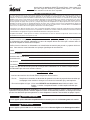
Thank You
for selecting a QUALITY product by Lincoln Electric. We want you
to take pride in operating this Lincoln Electric Company product
••• as much pride as we have in bringing this product to you!
Read this Operators Manual completely before attempting to use this equipment. Save this manual and keep it
handy for quick reference. Pay particular attention to the safety instructions we have provided for your protection.
The level of seriousness to be applied to each is explained below:
WARNING
This statement appears where the information must be followed exactly to avoid serious personal injury or loss of life.
This statement appears where the information must be followed to avoid minor personal injury or damage to this equipment.
CAUTION
Please Examine Carton and Equipment For Damage Immediately
When this equipment is shipped, title passes to the purchaser upon receipt by the carrier. Consequently, Claims
for material damaged in shipment must be made by the purchaser against the transportation company at the
time the shipment is received.
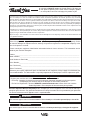
Please record your equipment identification information below for future reference. This information can be
found on your machine nameplate.
Product _________________________________________________________________________________
Model Number ___________________________________________________________________________
Code Number or Date Code_________________________________________________________________
Serial Number____________________________________________________________________________
Date Purchased___________________________________________________________________________
Where Purchased_________________________________________________________________________
Whenever you request replacement parts or information on this equipment, always supply the information you
have recorded above. The code number is especially important when identifying the correct replacement parts.
On-Line Product Registration
- Register your machine with Lincoln Electric either via fax or over the Internet.
• For faxing: Complete the form on the back of the warranty statement included in the literature packet
accompanying this machine and fax the form per the instructions printed on it.
• For On-Line Registration: Go to our
WEB SITE at www.lincolnelectric.com. Choose “Quick Links” and then
“Product Registration”. Please complete the form and submit your registration.
CUSTOMER ASSISTANCE POLICY
The business of The Lincoln Electric Company is manufacturing and selling high quality welding equipment, consumables, and cutting equip-
ment. Our challenge is to meet the needs of our customers and to exceed their expectations. On occasion, purchasers may ask Lincoln
Electric for advice or information about their use of our products. We respond to our customers based on the best information in our posses-
sion at that time. Lincoln Electric is not in a position to warrant or guarantee such advice, and assumes no liability, with respect to such infor-
mation or advice. We expressly disclaim any warranty of any kind, including any warranty of fitness for any customer’s particular purpose,
with respect to such information or advice. As a matter of practical consideration, we also cannot assume any responsibility for updating or
correcting any such information or advice once it has been given, nor does the provision of information or advice create, expand or alter any
warranty with respect to the sale of our products.
Lincoln Electric is a responsive manufacturer, but the selection and use of specific products sold by Lincoln Electric is solely within the control
of, and remains the sole responsibility of the customer. Many variables beyond the control of Lincoln Electric affect the results obtained in
applying these types of fabrication methods and service requirements.
Subject to Change – This information is accurate to the best of our knowledge at the time of printing. Please refer to www.lincolnelectric.com
for any updated information.

A-1A-1 INSTALLATION
WIRE FEEDER WELDERS (125, 140, 180 MODELS)
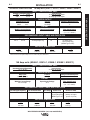
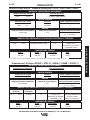
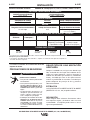
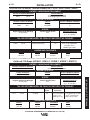
TECHNICAL SPECIFICATIONS 180 Amp units (K2481-1, K2515-1, K2659-1, K2689-1, K2698-1)
INPUT – SINGLE PHASE ONLY
RATED OUTPUT
OUTPUT
Standard Voltage/Frequency Input Current
230 V 60 Hz 20 Amps @ rated output
208 V 60 Hz 20 Amps @ rated output
Voltage/Duty Cycle Current Voltage at Rated Amperes
230 V 30% 130 Amps 20
208 V 30% 130 Amps 17
Welding Current Range Open Circuit Voltage Wire Speed Range
30-180 Amps 34 V 50 - 500 in/min.
(1.3 - 12.7 m/min.)
Input Voltage/Frequency Fuse or Breaker Size1Input Amps Power Cord
230 V 60 Hz 40 Amp Super Lag 20 50 Amp, 250 V,
Three Prong Plug
(NEMA Type 6-50P)
RECOMMENDED INPUT CABLE AND FUSE SIZES
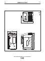
Height Width Depth Weight
13.7 in 10.15 in 17.9 in 64 Ibs
347 mm 258 mm 454 mm 29 kg
PHYSICAL DIMENSIONS
1 If connected to a circuit protected by fuses use Time Delay Fuse marked “D”.
140 Amp units (K2480-1, K2514-1, K2658-1, K2688-1, K2697-1)
INPUT – SINGLE PHASE ONLY
RATED OUTPUT
OUTPUT
Standard Voltage/Frequency Input Current
120 V / 60 Hz 20 Amps @ rated output
Duty Cycle Current Voltage at Rated Amperes
20% Duty Cycle 90 Amps 19.5
Welding Current Range Open Circuit Voltage Wire Speed Range
30-140 Amps 33 V 50 - 500 in/min.
(1.3 - 12.7 m/min.)
Input Voltage/Frequency Fuse or Breaker Size1,2 Input Amps Power Cord Extension Cord
120 V 60 Hz 20 Amp 20 15 Amp, 125 V,
3 Conductor # 12 AWG
Three Prong Plug (4mm2) or Larger
(NEMA Type 5-15P) up to 50 ft.(15.2m)
RECOMMENDED INPUT CABLE AND FUSE SIZES
Height Width Depth Weight
13.7 in 10.15 in 17.9 in 54 Ibs
347 mm 258 mm 454 mm 24.5 kg
PHYSICAL DIMENSIONS
1If connected to a circuit protected by fuses use Time Delay Fuse marked “D”.
OPERATOR’S MANUAL

INSTALLATION
WIRE FEEDER WELDERS (125, 140, 180 MODELS)
A-2
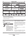
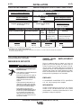
TECHNICAL SPECIFICATIONS 125 Amp units (K2479-1, K2513-1, K2696-1, K2699-1, K2785-1)
INPUT – SINGLE PHASE ONLY
RATED OUTPUT
OUTPUT
Standard Voltage/Frequency Input Current
120 V / 60 Hz 20 Amps @ rated output
Duty Cycle Current Voltage at Rated Amperes
20% Duty Cycle 90 Amps 19
Welding Current Range Maximum-Open Circuit Voltage Wire Speed Range
30-125 Amps 33 V 50 - 500 in/min.
(1.3 - 12.7 m/min.)
Input Voltage / Frequency Fuse or Breaker Size1,2 Input Amps Power Cord Extension Cord
120 V 60 Hz 20 Amp 20 15 Amp, 125 V,
3 Conductor # 12 AWG
Three Prong Plug (4mm2) or Larger
(NEMA Type 5-15P) up to 50 ft.(15.2m)
RECOMMENDED INPUT CABLE AND FUSE SIZES
Height Width Depth Weight
13.7 in 10.15 in 17.9 in 48 Ibs
347 mm 258 mm 454 mm 21.7 kg
PHYSICAL DIMENSIONS
1If connected to a circuit protected by fuses use Time Delay Fuse marked “D”.
A-2
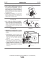
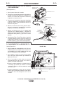
SELECT SUITABLE LOCATION
Locate the welder in a dry location where there is free
circulation of clean air into the louvers in the back and
out the front of the unit. A location that minimizes the
amount of smoke and dirt drawn into the rear louvers
reduces the chance of dirt accumulation that can
block air passages and cause overheating.
STACKING
WIRE FEEDER WELDER(125, 140, 180 MODELS)
cannot be stacked.
TILTING
Each machine must be placed on a secure, level sur-
face, directly or on recommended cart. The machine
may topple over if this procedure is not followed.
Read entire installation section before starting
installation.
SAFETY PRECAUTIONS
ELECTRIC SHOCK can kill.
• Only qualified personnel should perform
this installation.
• Only personnel that have read and under-
stood the POWER MIG Operating Manual
should install and operate this equipment.
• Machine must be plugged into a receptacle
which is grounded per any national, local
or other applicable electrical codes.
• The POWER MIG power switch is to be in
the OFF (“O”) position when installing
work cable and gun and when connecting
power cord to input power.
WARNING
2Requirements For Maximum Output
In order to utilize the maximum output capability of
the machine, a branch circuit capable of 25 amps at
120 volts, 60 Hertz is required.

A-3
INSTALLATION
WIRE FEEDER WELDERS (125, 140, 180 MODELS)
A-3
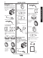
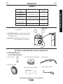
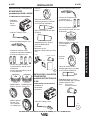
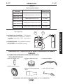
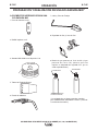
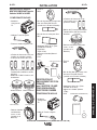
INCLUDED COMPONENTS
• Wire Feeder
Welder.
• Work Cable & Clamp.
• Magnum 100L Welding Gun.
• 3 .035 Contact Tips (1 installed
on the welding gun).
• 3 .025 Contact Tips.
• Spool of .035 diameter NR-
211MP Innershield Flux-cored
Wire.
• Spool of .025 diameter L-56 MIG
Wire.
•
.025-.030 Smooth Drive Roll
• .035 Smooth Drive Roll
• .030 -.045 Knurled
Drive Roll
(Installed on
Machine)
.025
.025
.025
.035
.035
NR-211 MP
WIRE
L-56 MIG
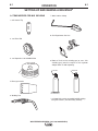
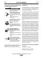
• Magnum 100L Welding Gun.
• 3 .035 Contact Tips (1 installed on
the welding gun).
• Spool of .035 diameter NR-
211MP Innershield Flux-cored
Wire.
• .030 -.045 Knurled Drive Roll
(Installed on
Machine)
• Handshield
• Black Flux-cored Gasless Gun
Nozzle (Installed on Welding Gun)
• 2” Spindle Adapter (For 8” Reel of
wire)
• Learn to Weld (LTW1 Manual)
• DVD
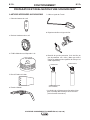
IDENTIFY AND LOCATE
COMPONENTS
for 140 AMP and 180 AMP UNITS
.035
.035
.035 NR-211 MP
F
L
U
X
-
C
O
R
E
D
W
I
R
E
LTW1
"LEARN TO WELD"
DVD
2" SPINDLE ADAPTER (FOR 8" REEL OF WIRE)
LINCOLN
ELECTRIC
®
• Handshield
• Black Flux-cored Gasless Gun
Nozzle (Installed on Welding
Gun)
• Brass MIG Gas Gun Nozzle
• 2” Spindle Adapter (For 8” Reel of
wire)
• Regulator
• Gas Hose
• Learn to Weld (LTW1 Manual)
• DVD
• INCLUDED COMPONENTS
• Wire Feeder
Welder.
• Work Cable & Clamp.
LINCOLN
ELECTRIC
®
LTW1
"LEARN TO WELD"
DVD
GAS HOSE
REGULATOR 2" SPINDLE ADAPTER (FOR 8" REEL OF WIRE)
IDENTIFY AND LOCATE
COMPONENTS
for 125 AMP FLUX CORE UNIT
OPERATOR’S MANUAL

B-1
OPERATION
B-1
WIRE FEEDER WELDERS (125, 140, 180 MODELS)
COMMON WELDING ABBREVIATIONS
GMAW (MIG)
• Gas Metal Arc Welding
FCAW (Innershield or Outershield)
• Flux Core Arc Welding
PRODUCT DESCRIPTION (PRODUCT
CAPABILITIES)
These small portable wire feed welders are capable of
MIG welding on steel, stainless steel, and aluminum.
They are also capable of flux-cored welding on mild
steel.
MIG welding stands for Metal Inert Gas welding and
requires a separate bottle of shielding gas to protect
the weld until it cools. Appropriate shielding gas
based on the type of material you are welding can be
purchased separately from your local welding gas dis-
tributor. MIG welding is ideal for welding on thinner
and clean materials when a very clean excellent cos-
metic looking weld is required. An example would be
automotive body panels.
Self Sheilding Flux-cored Welding does not require
separate shielding gas to protect the weld since the
welding wire has special additives known as flux to
protect the weld until it cools. Flux-cored welding is
ideal for medium to thicker material and if welding on
painted or rusty steel. Flux-cored welding is also ideal
in outdoor applications where windy conditions might
blow the MIG shielding gas away from the weld. Flux-
cored welding produces a good looking weld but does
not produce an excellent weld appearance as MIG
welding does.
Your machine includes the necessary items to weld
with either the MIG or the flux-cored welding process
on steel. To weld on stainless steel optional stainless
steel welding wire can be purchased separately. This
machine can weld aluminum using .035 diameter
4043 aluminum welding wire. Since aluminum weld-
ing wire is soft an optional aluminum spool gun is rec-
ommended for best results. A welding Procedure
Decal is located inside machine door to help provide
suggested settings for welding.
Read entire operation section before
operating the WIRE FEEDER WELDERS.
ELECTRIC SHOCK can kill.
• Do not touch electrically live
parts or electrode with skin or
wet clothing. Insulate yourself
from work and ground.
• Always wear dry insulating
gloves.
FUMES AND GASES can be
dangerous.
• Keep your head out of fumes.
• Use ventilation or exhaust to
remove fumes from breathing
zone.
WELDING SPARKS can
cause fire or explosion.
• Keep flammable material away.
• Do not weld on closed contain-
ers.
ARC RAYS can burn eyes
and skin.
• Wear eye, ear and body protec-
tion.
Observe all safety information throughout
this manual.
------------------------------------------------------------
WARNING

B-2
OPERATION
B-2
WIRE FEEDER WELDERS (125, 140, 180 MODELS)
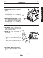
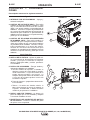
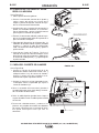
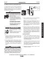
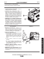
CONTROLS AND SETTINGS
This machine has the following controls:
See Figure B.1
1. POWER SWITCH – Turns power on and off to the
machine.
2. ARC VOLTAGE CONTROL – This knob sets the
output voltage of the machine. Along with wire feed
speed (WFS) this control sets a weld procedure.
Refer to the procedure decal on the inside wire
drive compartment door to set a correct welding
procedure based on type of material and thickness
being welded.
3. WIRE FEED SPEED CONTROL (WFS) – The knob
sets the speed that the machine feeds wire. Along
with arc voltage this control sets a weld procedure.
Refer to the procedure decal on the inside wire
drive compartment door to set a correct welding
procedure based on type of material and thickness
being welded.
See Figure B.2
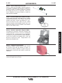
4. GUN TRIGGER – Depress the trigger to activates
the wire drive to feed wire and energizes the output
of the machine. Depress the trigger to weld and
release the trigger to stop welding.
5. WELDING GUN – Delivers wire and welding cur-
rent to the weld.
a. Gun Liner – wire travels through the liner from
the wire drive. The gun liner will feed .025 to .035
wire. The 180A machine can weld with .045 wire
if an optional .045 liner is installed in the gun.
b. Contact Tip – provides electrical contact to the
wire.
c. Nozzle – When flux-cored welding the black noz-
zle protects the mounting threads on the gun.
When MIG welding the brass nozzle funnels the
shielding gas to the weld.
6. WORK CLAMP & CABLE – Clamps to the work
piece being welded and completes the electrical
welding circuit.
7. GUN TRIGGER CONNECTOR RECEPTACLE –
Plug the 4 pin gun trigger connector into this recep-
tacle.
1
3
2
FIGURE B.1
FIGURE B.2
4
5a
5b
5
5c
67
.035"(0.9mm)
NR-211-MP
WIRE SPOOL
OPERATOR’S MANUAL

B-3
OPERATION
B-3
WIRE FEEDER WELDERS (125, 140, 180 MODELS)
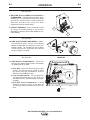
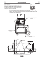
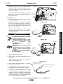
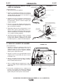
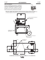
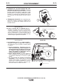
See Figure B.3
8. WELDING GUN CONNECTOR BUSHING &
THUMBSCREW – Provides electrical power to the
welding gun. The thumbscrew holds the welding
gun into the connector block. (Front of Machine,
Side Door and Wire Drive Cover have been
removed for clarity of Items 8 and 9).
9. OUTPUT TERMINALS –These connections allow
to change the welding polarity of the machine
depending on whether you are MIG welding or flux-
cored welding.
See Figure B.4
10. WIRE SPOOL SPINDLE AND BRAKE – Holds a
4 inch diameter spool. Use the 2 inch spindle
adapter included with the machine to use 8 inch
diameter spools. The thumbscrew sets the brake
friction to prevent the spool from over rotating
when the trigger is released.
See Figure B.5
11. WIRE DRIVE & COMPONENTS – Feeds wire
from the wire spool through the drive and through
the welding gun to the weld.
a. Drive Roll – Drives the wire through the drive
system. The drive roll has a groove to match
the specific wire type and diameter. Refer to
Table B.1 for available drive rolls.
b. Liner & Outgoing Guide – The liner guides the
wire between the bearing on the Pivot Arm
Assembly and Drive Roll and through the outgo-
ing guide.
c. Drive Roll Tension Thumbscrew – Turning
clockwise increases the force on the drive roll
and turning counterclockwise decreases the
force.
8
9
FIGURE B.3
FIGURE B.4
FIGURE B.5
WIRE SPOOL
.035" (0.9mm)
NR-211-MP
PIVOT ARM ASSEMBLY
TENSION ARM ASSEMBLY
LINER
DRIVE ROLL
OUTGOING GUIDE
BEARING

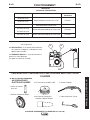
A. ITEMS NEEDED FOR
FLUX CORED WELDING
1. 035 Contact Tip
2. Knurled Drive Roll
3. .035 NR-211MP Flux-Cored Wire
4. Black Flux Cored gun nozzle
5. Welding Gun
7. Work Cable & Clamp
.035
.035 NR-211 MP
F
L
U
X
-
C
O
R
E
D
W
I
R
E
SETTING UP AND MAKING A FLUX-CORED WELD
B-4
OPERATION
B-4
WIRE FEEDER WELDERS (125, 140, 180 MODELS)
TABLE B.1
DRIVE ROLLS
Wire Diameter &
Type
.025 MIG wire
.030 MIG wire
.035 MIG wire
.030 flux-cored
.035 flux-cored
.045 flux-cored
Drive Roll
.025/.030 Smooth Drive Roll
.035 Smooth Drive Roll
.030/.045 Knurled Drive Roll
.030/.045 Knurled Drive Roll
Drive Roll Part
Number
KP2529-1
KP2529-2
KP2529-3
KP2529-3
See Figure B.6
12. CIRCUIT BREAKER – If the rated input current of
the machine is exceeded this circuit breaker will
trip. Press to reset.
13. GAS INLET –Shielding gas connects to this inlet
(This is optional on 125 Amp Unit.)
12 13
FIGURE B.6
OPERATOR’S MANUAL

B-5
OPERATION
B-5
WIRE FEEDER WELDERS (125, 140, 180 MODELS)
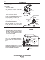
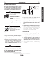
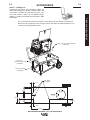
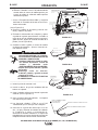
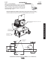
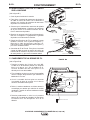
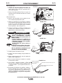
B. CONNECT LEADS AND CABLES ON
THE MACHINE
(See Figure B.7)
1. Open the case side door
2. Slide the connector end of the gun and cable
through the hole in the machine front and into the
gun connector bushing on the wire drive.
3. Make sure the gun connector end is seated fully
into the wire drive and tighten the molded hand
screw to secure the gun connector.
4. Plug the gun trigger lead connector into the 4 pin
gun trigger receptacle on the machine front.
5. Wire Drive Polarity. Flux cored welding requires
negative (-) polarity. Connect the short power
cable from the wire drive to the negative (-) output
terminal and tighten threaded knob.
6. Work Lead Connection. Slide the lugged end of
the work cable through the hole in the machine
front and place on the positive (+) output terminal
and tighten threaded knob.
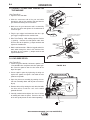
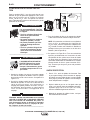
C. LOAD WIRE SPOOL
(See Figure B.8)
1. Locate the blue labeled 4" diameter spool of .035
NR-211MP flux-cored wire and place onto wire
spool spindle. Orient the spool so that the wire
feeds off the top of the spool.
2. Secure spool in place by tightening the wing nut
against the against the spacer that holds the wire
spool on the spindle.
3. Open the pivot arm assembly by rotating the ten-
sion arm assembly down and lift pivot arm assem-
bly up.
4. Remove drive roll
by turning the twist lock that holds
the drive roll on. Install the .030/.045 knurled drive
roll.
5. Carefully unwind and straighten the first six inches of
welding wire from the spool. Do not let the end of the
wire go to prevent the wire from unspooling.
WORK CLAMP
(4 PIN)
TRIGGER RECEPTACLE
PLUGGED IN
CONNECTOR
END ATTACH
ALL COMPONENTS SHOWN CONNECTED
(FRONT AND SIDE DOOR IS REMOVED
FOR CLARITY)
SHORT POWER
CABLE NEGATIVE "-"
OUTPUT TERMINAL
WORK LEAD
CONNECTION
POSITIVE "+"
OUTPUT TERMINAL
MOLDED HAND SCREW TO
TIGHTEN CONNECTOR
BUSHING
GUN AND CABLE
WORK CLAMP
(4 PIN)
LEAD CONNECTOR
TERMINAL END
(FITS ON STUD INSIDE
SEE FIGURE BELOW)
SLIDE
CONNECTOR
END HERE
OPEN LATCH DOOR
FIGURE B.7
WIRE SPOOL
.035" (0.9mm)
NR-211-MP
PIVOT ARM ASSEMBLY
TENSION ARM ASSEMBLY DOWN
LINER
TWIST LOCK
DRIVE ROLL
OUTGOING GUIDE
BEARING
FIGURE B.8

B-6
OPERATION
B-6
WIRE FEEDER WELDERS (125, 140, 180 MODELS)
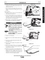
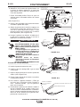
(See Figure B.9)
6. Feed the wire through the inlet liner, over the
drive roll groove, thru the outgoing guide and
wire drive outlet on the gun side.
7. Close the Pivot Arm Assembly and secure by piv-
oting the Tension Arm Assembly back to the up
position.
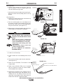
(See Figure B.10)
8. Remove the nozzle from the gun and contact tip
and straighten the gun out flat.
9. Turn the machine power to on and depress the
gun trigger to feed the wire through the gun liner
until the wire comes out of the threaded end of
the gun several inches. (See figure B.11)
10. When trigger is released spool of wire should not
unwind. Adjust wire spool brake accordingly.
MOVING PARTS AND ELECTRICAL
CONTACT CAN CAUSE INJURY OR BE
FATAL.
•When the gun trigger is depressed
drive rolls, spool of wire and elec-
trode are ELECTRICALLY LIVE (HOT).
• Keep away from moving parts and
pinch points.
• Keep all Doors, Covers, panels and
guards securely in place.
DO NOT REMOVE OR CONCEAL
WARNING LABELS.
------------------------------------------------------------------------
11. Install the .035 contact tip
12. Install the black flux cored welding nozzle to the
gun.
13. Trim the wire stickout to 3/8” from the contact tip.
(See Figure B.12)
14. Close the case side door. The machine is now
ready to weld.
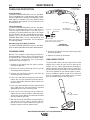
15. Read "Learn to Weld" (LTW1) that is included
with the machine or watch the "How to Weld"
DVD included with the machine.
16. Based on the thickness of the material you are
going to weld and the type and diameter of the
welding wire set the voltage and the wire feed
speed per the procedure decal attached to the
inside of the wire drive compartment door.
.035"(0.9mm)
NR-211-MP
WIRE SPOOL
REMOVED NOZZLE
REMOVED CONTACT TIP
LAY CABLE AND GUN STRAIGHTEN
IN THIS POSITION
.035"(0.9mm)
NR-211-MP
WIRE SPOOL
PLUG IN POWER
INPUT CORD
DEPRESS TRIGGER
TO ACTIVATE WIRE,
WHICH FEEDS THE WIRE
THRU THE LINER.
FEED WIRE
APPROXIMATELY 4.00"
FROM THE GUN TUBE END
ON/OFF
SWITCH
WORK CLAMP AND CABLE
ROTATION
TENSION ARM ASSEMBLY
LOCKED IN UP POSITION
PIVOT ARM ASSEMBLY
WITH BEARING PRESSING
AGAINST DRIVE ROLL
DIRECTION
OF WIRE
WIRE SPOOL
.035" (0.9mm)
NR-211-MP
DRIVE ROLL
LINER
OUTGOING GUIDE
BEARING
SLIDE WIRE
INTO GUN
CONNECTOR
SIDE
FIGURE B.10
FIGURE B.11
WARNING
INSTALL .035 CONTACT TIP
INSTALL BLACK FLUX-CORED NOZZLE
TRIM WIRE
STICKOUT
3/8"(9.5mm)
from the Contact Tip
FIGURE B.9
FIGURE B.12
OPERATOR’S MANUAL

B-7
OPERATION
B-7
WIRE FEEDER WELDERS (125, 140, 180 MODELS)
A. ITEMS NEEDED FOR MIG WELDING
1. 025 Contact Tip
3. .025 Drive Roll
4. .025 SuperArc L-56 Solid MIG Wire
5. Brass gun nozzle
6. Welding Gun
.025
WIRE
L-56 MIG
7. Work Cable & Clamp
8. Gas Regulator & Gas Line
9. Bottle of 75/25 Ar/
CO2
shielding gas (or 100%
CO2
shielding gas) (note this requires a
CO2
regulator
adapter which is sold separately.
.025
75/25
FEMALE END
MIXES
MALE END
CO
100%
2
(REQUIRES ADAPTER
SOLD SEPARATELY)
SETTING UP AND MAKING A MIG WELD*
*125 Amp Units can be upgraded for MIG welding
using KIT K2526-1 (See Accessory Section).

B-8
OPERATION
B-8
WIRE FEEDER WELDERS (125, 140, 180 MODELS)
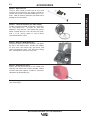
B. INSTALL SHIELDING GAS
MIG welding requires an appropriate bottle of shielding
gas. For mild steel either a cylinder bottle of Ar/CO2or
100% CO2can be used refer to the following instruc-
tions to properly connect shielding gas to the machine.
CYLINDER may explode if dam-
aged. Keep cylinder upright and
chained to support
• Keep cylinder away from areas
where it may be damaged.
• Never lift welder with cylinder
attached.
• Never allow welding electrode to
touch cylinder.
• Keep cylinder away from welding
or other live electrical circuits.
-----------------------------------------------------------------------
WARNING 75/25
FEMALE END
MALE END
CO
S19298
REGULATOR
ADAPTER
PLASTIC
WASHER
MIXES
100%
2
3. Attach the flow regulator to the cylinder valve and
tighten the union nut securely with a wrench.
NOTE: If connecting to 100%
CO2
cylinder, a
CO2
regulator adapter is required. Purchase separately
S19298
CO2
adapter be sure to install plastic washer
included in the fitting on the bottle side.(See Figure
B.13 )
4. Refer to Figure B.13. Attach one end of inlet gas hose
to the outlet fitting of the flow regulator and tighten the
union nut securely with a wrench. Connect the other
end to the machine Solenoid Inlet Fitting (5/8-18
female threads — for CGA — 032 fitting). Make cer-
tain the gas hose is not kinked or twisted.
FIGURE B.13
BUILDUP OF SHIELDING GAS may
harm health or kill.
• Shut off shielding gas supply
when not in use.
1. Secure the cylinder to a wall or other stationary
support to prevent the cylinder from falling over.
Insulate the cylinder from the work circuit and earth
ground. Refer to Figure B.13.
2. With the cylinder securely installed, remove the
cylinder cap. Stand to one side away from the out-
let and open the cylinder valve very slightly for an
instant. This blows away any dust or dirt which may
have accumulated in the valve outlet.
BE SURE TO KEEP YOUR FACE AWAY FROM
THE VALVE OUTLET WHEN “CRACKING” THE
VALVE. Never stand directly in front of or behind
the flow regulator when opening the cylinder
valve. Always stand to one side.
------------------------------------------------------------------------
WARNING
WARNING
SHIELDING GAS
1. For
CO2
, open the cylinder very slowly. For argon-
mixed gas, open cylinder valve slowly a fraction of a
turn. When the cylinder pressure gauge pointer stops
moving, open the valve fully.
2. Set gas flow rate for 30 to 40 cubic feet per hour (14
to 18 I/min.) under normal conditions, increase to as
high as 40 to 50 CFH (18 to 23.5 I/min.) under drafty
(slightly windy) conditions.
3. Keep the cylinder valve closed, except when using
the machine.
OPERATOR’S MANUAL

B-9
OPERATION
B-9
WIRE FEEDER WELDERS (125, 140, 180 MODELS)
C. CONNECT LEADS AND CABLES ON
THE MACHINE
(See Figure B.14)
1. Open the case side door.
2. Slide the connector end of the gun and cable
through the hole of the machine front and into the
gun connector bushing on the wire drive.
3. Make sure the gun connector end is seated fully
into the wire drive and tighten the thumbscrew to
secure the gun.
4. Plug the gun trigger lead connector into the 4 pin
gun trigger receptacle on the machine front.
5. Wire Drive Polarity. MIG welding requires Positive
(+) polarity. Connect the short power cable from
the wire drive to the positive (+) output terminal and
tighten the thumbscrew.
6. Work Lead Connection. Slide the lugged end of the
work cable through the hole in the machine front
and place on the negative (-) output terminal and
tighten thumbscrew.
D. LOAD WIRE SPOOL
(See Figure B.15)
1. Locate the green labeled 4" diameter spool of .025
L-56 solid MIG wire and place onto wire spool spin-
dle. Orient the spool so that the wire feeds off the
top of the spool.
2. Secure spool in place by tightening the wing nut
against the against the spacer that holds the wire
spool on the spindle.
3. Open the pivot arm assembly by rotating the ten-
sion arm assembly down and lift pivot arm assem-
bly up.
4. Remove drive roll
by turning the twist lock that holds
the drive roll on. Install the
.025-.035 smooth
grooved
drive roll.
5. Carefully unwind and straighten the first six inches
of welding wire from the spool. Do not let the end
of the wire go to prevent the wire from unspooling.
CASE SIDE DOOR
SHORT POWER
CABLE POSITIVE "+"
OUTPUT TERMINAL
WORK LEAD
CONNECTION
NEGATIVE "-"
OUTPUT TERMINAL
LOCATE COMPONENTS
TO CONNECT TO THE
FRONT OF MACHINE
WORK CLAMP
(4 PIN)
TRIGGER RECEPTACLE
PLUGGED IN
CONNECTOR
END ATTACH
ALL COMPONENTS SHOWN CONNECTED
(FRONT AND SIDE DOOR IS REMOVED
FOR CLARITY)
MOLDED HAND SCREW TO
TIGHTEN CONNECTOR
BUSHING
GUN AND CABLE
WORK CLAMP
(4 PIN)
LEAD CONNECTOR
TERMINAL END
(FITS ON STUD INSIDE
SEE FIGURE BELOW)
SLIDE
CONNECTOR
END HERE
OPEN LATCH DOOR
FIGURE B.15
FIGURE B.14
PIVOT ARM ASSEMBLY
TENSION ARM ASSEMBLY DOWN
LINER
TWIST LOCK
DRIVE ROLL
OUTGOING GUIDE
BEARING
WIRE SPOOL
.025" (0.6mm)
L
-
5
6
S
O
L
I
D
M
I
G

B-10
OPERATION
B-10
WIRE FEEDER WELDERS (125, 140, 180 MODELS)
(See Figure B.16)
6. Feed the wire through the inlet liner, over the drive
roll groove, thru the outgoing guide and wire drive
outlet on the gun side.
7. Close the Pivot Arm Assembly and secure by piv-
oting the Tension Arm Assembly back to the up
position.
(See Figure B.17)
8. Remove the nozzle from the gun and contact tip
and straighten the gun out flat.
9. Turn the machine power to on and depress the
gun trigger to feed the wire through the gun liner
until the wire comes out of the threaded end of the
gun several inches. (See Figure B.18)
10. When trigger is released spool of wire should not
unwind. Adjust wire spool brake accordingly.
MOVING PARTS AND ELECTRICAL
CONTACT CAN CAUSE INJURY OR BE
FATAL.
•When the gun trigger is depressed
drive rolls, spool of wire and electrode
are ELECTRICALLY LIVE (HOT).
• Keep away from moving parts and
pinch points.
• Keep all Doors, Covers, panels and
guards securely in place.
DO NOT REMOVE OR CONCEAL
WARNING LABELS.
-----------------------------------------------------------------------
11. Install the .025 contact tip.
12. Install the brass gas MIG welding nozzle to the
gun.
13. Trim the wire stickout to 3/8 from the nozzle end.
(See Figure B.19)
14. Close the case side door. The machine is now
ready to weld.
15. Read "Learn to Weld" (LTW1) that is included with
the machine or watch the "How to Weld" DVD
included with the machine.
16. Based on the thickness of the material you are
going to weld and the type and diameter of the
welding wire set the voltage and the wire feed
speed per the procedure decal attached to the
inside of the wire drive compartment door.
TENSION ARM ASSEMBLY
LOCKED IN UP POSITION
PIVOT ARM ASSEMBLY
WITH BEARING PRESSING
AGAINST DRIVE ROLL
DIRECTION
OF WIRE
DRIVE ROLL
LINER
OUTGOING GUIDE
BEARING
SLIDE WIRE
INTO GUN
CONNECTOR
SIDE
WIRE SPOOL
.025" (0.6mm)
L
-
5
6
S
O
L
I
D
M
I
G
WIRE SPOOL
.025" (0.6mm)
L
-
5
6
S
O
L
I
D
M
I
G
REMOVED NOZZLE
REMOVED CONTACT TIP
LAY CABLE AND GUN STRAIGHTEN
IN THIS POSITION
WIRE SPOOL
.025" (0.6mm)
L
-
5
6
S
O
L
I
D
M
I
G
PLUG IN POWER
INPUT CORD
DEPRESS TRIGGER
TO ACTIVATE WIRE,
WHICH FEEDS THE WIRE
THRU THE LINER.
FEED WIRE
APPROXIMATELY 4.00"
FROM THE GUN TUBE END
ON/OFF
SWITCH
WORK CLAMP AND CABLE
RO TATION
INSTALL .025 CONTACT TIP
INSTALL BRASS NOZZLE
TRIM WIRE
STICKOUT
3/8"(9.5mm)
from the Brass Nozzle
FIGURE B.17
FIGURE B.18
FIGURE B.19
FIGURE B.16
WARNING
OPERATOR’S MANUAL

B-11
OPERATION
B-11
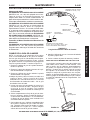
1. Follow the MIG welding steps in the previous sec-
tion.
2. Connect a bottle of 100% Argon shielding Gas per
previous section.
3. Disconnect Magnum 100L Gun.
4. Install optional K2532-1 Magnum 100SG spool gun
per instructions included with gun.
5. Set Gun selector toggle switch to Spool Gun posi-
tion. (See Figure B.20)
FIGURE B.20
6. Turn machine on and make weld per recommended
settings on Procedure Decal inside machine door.
WIRE FEEDER WELDERS (125, 140, 180 MODELS)
SETTING UP AND MAKING A ALUMINUM WELD USING SPOOL GUN
WARNING
La page charge ...
La page charge ...
La page charge ...
La page charge ...
La page charge ...
La page charge ...
La page charge ...
La page charge ...
La page charge ...
La page charge ...
La page charge ...
La page charge ...
La page charge ...
La page charge ...
La page charge ...
La page charge ...
La page charge ...
La page charge ...
La page charge ...
La page charge ...
La page charge ...
La page charge ...
La page charge ...
La page charge ...
La page charge ...
La page charge ...
La page charge ...
La page charge ...
La page charge ...
La page charge ...
La page charge ...
La page charge ...
La page charge ...
La page charge ...
La page charge ...
La page charge ...
La page charge ...
La page charge ...
La page charge ...
La page charge ...
La page charge ...
La page charge ...
La page charge ...
La page charge ...
La page charge ...
La page charge ...
La page charge ...
La page charge ...
La page charge ...
La page charge ...
La page charge ...
La page charge ...
La page charge ...
La page charge ...
La page charge ...
La page charge ...
La page charge ...
La page charge ...
La page charge ...
La page charge ...
La page charge ...
-
 1
1
-
 2
2
-
 3
3
-
 4
4
-
 5
5
-
 6
6
-
 7
7
-
 8
8
-
 9
9
-
 10
10
-
 11
11
-
 12
12
-
 13
13
-
 14
14
-
 15
15
-
 16
16
-
 17
17
-
 18
18
-
 19
19
-
 20
20
-
 21
21
-
 22
22
-
 23
23
-
 24
24
-
 25
25
-
 26
26
-
 27
27
-
 28
28
-
 29
29
-
 30
30
-
 31
31
-
 32
32
-
 33
33
-
 34
34
-
 35
35
-
 36
36
-
 37
37
-
 38
38
-
 39
39
-
 40
40
-
 41
41
-
 42
42
-
 43
43
-
 44
44
-
 45
45
-
 46
46
-
 47
47
-
 48
48
-
 49
49
-
 50
50
-
 51
51
-
 52
52
-
 53
53
-
 54
54
-
 55
55
-
 56
56
-
 57
57
-
 58
58
-
 59
59
-
 60
60
-
 61
61
-
 62
62
-
 63
63
-
 64
64
-
 65
65
-
 66
66
-
 67
67
-
 68
68
-
 69
69
-
 70
70
-
 71
71
-
 72
72
-
 73
73
-
 74
74
-
 75
75
-
 76
76
-
 77
77
-
 78
78
-
 79
79
-
 80
80
-
 81
81


Lincoln Electric EASY-MIG 180 Le manuel du propriétaire
- Catégorie
- Système de soudage
- Taper
- Le manuel du propriétaire
dans d''autres langues
Documents connexes
-
Lincoln Electric Invertec V130-S Mode d'emploi
-
Lincoln Electric K2513-1 Manuel utilisateur
-
-
Lincoln Electric IM756-A Manuel utilisateur
-
-
Lincoln Electric Pro-MIG 180 Mode d'emploi
-
-
-