Mr. Heater HeatStar HS25NG Manuel utilisateur
- Catégorie
- Chauffe-eau
- Taper
- Manuel utilisateur

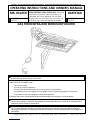
GAS FIRED INFRA-RED WORKSHOP HEATER
ENERCO GROUP, INC., 4560 W. 160TH ST., CLEVELAND, OHIO 44135 · 216-916-3000
WARNING: If the information in this manual is not followed exactly, a fire or explosion may result causing
property damage, personal injury, or loss of life.
- Do not store or use gasoline or other flammable vapors and liquids in the vicinity of this or any other appliance.
- WHAT TO DO IF YOU SMELL GAS
• Shut off gas supply
• Do not try to light any appliance
• Do not touch an electrical switch; do not use any phone in your building.
• Immediately call your gas supplier from a neighbor’s phone. Follow the gas supplier’s instructions.
• If you cannot reach your gas supplier, call the fire department.
- Installation and service must be performed by a qualified installer, service agency, or the gas supplier.
WARNING: This is an unvented gas-fired heater. It uses air (oxygen) from the room in which it is installed.
Provisions for adequate combustion and ventilation air must be provided. Refer to Fresh Air for Combustion and
Ventilation section on page 3 of this manual.
WARNING: Improper installation, adjustment, alteration, service or maintenance can cause property damage,
injury or death. Read the installation, operation, and maintenance instructions thoroughly before installing or
servicing this equipment. For assistance or additional information consult a qualified installer, service agency, or
gas supplier.
18673 Rev. D 06/06
Installer: Leave this manual with the appliance. Consumer: Retain this manual for future reference.
READ INSTRUCTIONS CAREFULLY: Read and
follow all instructions. Place instructions in a
safe place for future reference. Do not allow
anyone who has not read these instructions to
assemble, light, adjust or operate the heater.
MH25NG
MH25LP
MODEL
MODEL
OPERATING INSTRUCTIONS AND OWNER’S MANUAL
MR. HEATER HEATSTAR
HS25NG
HS25LP

WARNINGS
WARNING: Improper installation, adjustment,
alteration, service or maintenance can cause
property damage, injury or death. Read the
installation, operation, and maintenance instruc-
tions thoroughly before installing or servicing this
equipment. For assistance or additional informa-
tion consult a qualified installer, service agency, or
gas supplier.
WARNING: When used without fresh air, heater
may give off CARBON MONOXIDE, an odorless
poisonous gas. OPEN WINDOW AN INCH OR
TWO FOR FRESH AIR WHEN USING HEATER.
WARNING: This heater is equipped with a PILOT
LIGHT SAFETY SYSTEM. DO NOT TAMPER
WITH PILOT LIGHT SAFETY SYSTEM.
WARNING: If heater shuts off, do not relight until
you provide fresh air. If heater keeps shutting off,
have it serviced. Keep burner and control clean.
Open door for 5 minutes.
Maintain clearances as shown in Figure 2 or on
heater nameplate.
• DO NOT USE MATCH OR OTHER FLAME
FOR LEAK TESTING.
• DO NOT EXCEED 1/2 PSI INLET PRESSURE
TO HEATER.
DANGER: Carbon monoxide poisoning may lead to
death.
Carbon Monoxide Poisoning:
Early signs of carbon monoxide poisoning resemble the
flu, with headaches, dizziness, or nausea. If you have
these signs, the heater may not be working properly. Get
fresh air at once! Have heater serviced. Some people are
more affected by carbon monoxide than others. These
include pregnant women, persons with heart or lung
disease or anemia, those under the influence of alcohol,
and those at high altitudes.
CAUTION
• Never connect gas valve or thermostat to line voltage
or a transformer.
• If the infra-red color of the grid becomes dull when the
building furnace is operating, consult gas supplier on
correct gas supply piping sizes.
• This heater is for indoor installation only!
NOTE
Gasket binder material used in this heater assembly will
temporarily emit an odor and/or vapor. This condition will
clear up in approximately 20 minutes and thereafter will
not reoccur. Refer to Chapter 2 for ventilation.
TABLE OF CONTENTS
Chapter Title Page
I Introduction ............................................ 3
II Heater Installation .................................. 5
III Heater Operating Instructions ................. 10
IV Operator Maintenance Instructions ......... 12
V Replacement Parts List.......................... 15
2Installation instructions and Owner’s Manual
Model # MH25NG/LP HS25NG/LP

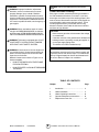
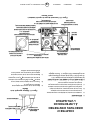
GAS CONTROL
VALVE
POWERPILE
GENERATOR EXHAUST
VENT
BASIC HEATER
WALL MOUNTING
BRACKET
THERMOSTAT
CABLE
THERMOSTAT
CHAPTER I
INTRODUCTION
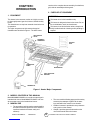
1. EQUIPMENT
This heater is the consumer version of a highly success-
ful, thoroughly tested, gas fired, infrared, industrial utility
heater.
This heater does not require an external electrical source
for operation.
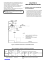
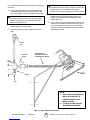
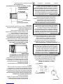
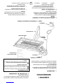
The major components of the heater and a typical
installation are identified in Figure 1. The basic heater
Figure 1. Heater Major Components
•The cover and the following page provide a safety
summary that attempts to gather all the warn-
ings used within the manual in one location.
•A table of contents is provided for easy reference
to any portion of the manual.
•Chapter 1 provides general information on the
use of this manual and on the heater.
consists of the complete burner assembly, flue deflector,
grid, reflector assembly and face guard.
2. PURPOSE OF EQUIPMENT
WARNINGS
This heater is for indoor installation only.
This heater is designed to heat indoor areas. Do not
use for inhabited or small, enclosed areas.
This heater is an ideal selection when a simple and
easily installed method of heating a utility building is
required.
3. MODELS COVERED IN THIS MANUAL
Model MH25NG/HS25NG is for use where natural gas is
intended fuel source. Model MH25LP/HS25LP is for use
where propane gas is the intended fuel source.
4. MANUAL USE
•The procedures and information contained within
this manual will allow purchaser of this heater to
install and maintain the heater safely and
efficiently.
3Installation instructions and Owner’s Manual
Model # MH25NG/LP HS25NG/LP

•Chapter 2 provides heater installation requirements
and information, such as: a) minimum distances
from heater components to combustible materials,
b) heater mounting requirements, c) venting
requirements, d) fuel supply requirements, e)
thermostat mounting.
•Chapter 3 covers startup, operation, and shutdown
of the heater.
•Chapter 4 provides operator maintenance instruc-
tions such as: troubleshooting, adjustments,
powerpile replacement and operator checks.
•Chapter 5 provides warranty and replacement
parts information.
5. GENERAL INFORMATION
• Your heater comes fully assembled and is tested
at the factory with the appropriate type of gas and
at the input pressures stated on the nameplate.
• Upon receipt and prior to attempting installation,
be sure to inspect the heater and its packaging for
damage and/or missing components. If damage is
found or missing components are suspected,
contact your dealer. See Chapter 5 for a complete
listing of items required for the safe and efficient
installation and use of this heater.
• Never attempt to operate the heater using a fuel
other than that specifically identified on the
nameplate.
• The installation of the heater must conform with all
local building codes or, in absence of governing
local codes, with the National Fuel Gas Code,
ANSI Z223.1 (NFPA 54). This code can be ob-
tained from either the: Canadian Standards
Association, 8501 East Pleasant Valley Road,
Cleveland, OH 44131; or, NFPA, Battery March
Park, Quincy, MA 02269.
• Canadian installations must comply with CAN/
CGA-B149.1.2 gas code which can be purchased
from Canadian Gas Association, 55 Scarsdale
Road, Don Mills, Ontario M3B 2R3.
• Contact factory when appliance is to be installed at
high altitudes. Factory supply high altitude conver-
sion kit with instructions and data plate.
• A plugged 1/8" N.P.T. Test Gage Connection is
provided on the heater gas control.
•See Tables 1 and 2 for heater specifications:
WARNING: Improper installation, adjustment, alteration,
service or maintenance can cause property damage,
injury or death. Read the installation, operation, and
maintenance instructions thoroughly before installing or
servicing this equipment. For assistance or additional
information consult a qualified installer, service agency,
or gas supplier.
•For additional information contact:
The factory.
•The following extra NFPA Manuals are helpful when
installing this heater in a location not anticipated in
this manual:
Number Related Subject
NFPA 88 Clearances to Combustible Surfaces
NFPA 409 Clearances to Combustible Surfaces
DO NOT EXCEED 1/2 PSI INLET PRESSURE TO HEATER
Table 1. BTU Ratings and Supply Pressures
MODEL BTU/HR. RATING GAS SUPPLY PRESSURE (W.C.) ORIFICE
NO. GAS MIN. MAX. MANIFOLD SIZE
NATURAL PROPANE NAT. L.P. NAT. L.P. NAT. L.P. NAT. L.P.
MH/HS25NG 25,000 — 7.0" — 14" — 6" — 45 —
MH/HS25LP — 22,000 — 11" — 14" — 10" — 55
Table 2. Heater Dimensions and Orifice Sizes
MODEL OPERATING ORIFICE SIZE INPUT SIZE
NO. PRESSURE BURNER PILOT BTU/H WIDTH LENGTH HEIGHT WEIGHT
MH/HS25NG 6.0"w.c. 45 .018 25.000 12-1/4" 29-3/4" 7" 20 lb.
MH/HS25LP 10"w.c. 55 .011 22,000 12-1/4" 29-3/4" 7" 20 lb.
4Installation instructions and Owner’s Manual
Model # MH25NG/LP HS25NG/LP

Provide adequate clearance to combustibles per Table 3 at
control end of heater for servicing and minimum on top and
sides for ventilation and combustion air supply.
A minimum clearance of 8’ above floor for public garages in
accordance with NFPA No. 88 most recent edition, or
Figure 1; whichever is larger.
Canadian installations in public garages must comply with
CGA 149B.1.9 most recent edition.
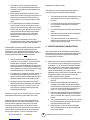
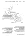
WARNING: Maintain clearances as shown in Figure 2
or on heater nameplate.
CHAPTER II
HEATER INSTALLATION
1. GENERAL INSTALLATION INFORMATION
AND REQUIREMENTS
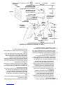
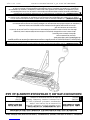
• The required minimum clearances to combustible
surfaces are illustrated in Figure 2 and Table 3.
As shown on Figure 2, the front of the heater is
installed at the minimum required clearance to
combustible surfaces and toward open space,
and then the other sides must have a minimum
clearance of 16 inches to combustible surfaces.
EXHAUST
VENT CEILING
14”
MINIMUM
16”
MINIMUM
48”
MINIMUM
OPEN
WORKSHOP DOOR
HEATER
WALL
BRACKET
16”
MINIMUM
14-1/2”
FLOOR LINE
30
1. ONLY FLUE SIDE OF HEATER CAN
BE ELEVATED (30o).
2. HEATER SIDE REFLECTOR MUST
BE HORIZONTAL.
NOTE:
Figure 2. Installation Clearances to Combustible Surfaces
Table 3. Installation, Ventilation and Mounting Information
BTU/HR. RATING NORMAL
MODEL GAS MOUNTING CLEARANCES TO COMBUSTIBLE SURFACES
NO. NAT. L.P. POSITION TOP SIDES BACK BELOW
MH/HS25NG 25,000 — 30o14" 16" 16" 48"
MH/HS25LP — 22,000 30o14" 16" 16" 48"
5Installation instructions and Owner’s Manual
Model # MH25NG/LP HS25NG/LP

•This heater may be mounted on any wall;
however, it is recommended that the heater be
mounted in the middle of the wall opposite any
overhead doors.
•When selecting installation locations for this
heater ensure that the opening of any exterior or
interior doors or windows will not violate mini-
mum clearances or contact any heater compo-
nents.
•If an overhead door is installed in the building,
verify that the heater is not installed in such a
way as to interfere with door operation and verify
that the door in its open position will not reduce
clearances below the minimum requirements.
Never mount the heater in such a way that
would position the heater above an opened
overhead door.
•In most cases the infiltration around your
uninsulated entry doors and windows will provide
enough air flow for efficient heater operation.
Unrestricted air flow during heater operation is essential
to prevent the area above the installed heater from
overheating. If your workshop/utility building is tightly
insulated (including windows, doors, openings, etc.) the
following ventilating methods must be followed:
•A single exhaust vent is supplied with your
heater for your convenience. This vent must be
located above the heater (preferably at the
highest point in the building interior) and it must
vent to the exterior of the building. An additional
vent is available from the factory for those having
a finished workshop or utility building.
•An intake vent, or equivalent, from the exterior of
the building and having an effective area of 75
square inches must be located below the heater
(preferably within 2 feet of the building’s floor).
•Openings equivalent to intake vent would be:
partially open doors and partially open windows.
•Openings of this size (5 inch by 13 inch, or 3
inch by 25 inch) will prevent dangerous heat
buildup above the heater.
Ensure that no gas lines or electrical wiring or conduits
will interfere with mounting of the heater to the wall.
Depending on local codes and requirements and the
installer’s skill level, the sizing and installation of gas
lines required to supply the heater may require the
assistance of a professional. If in doubt as to these
requirements, discuss the requirements of this manual
with the dealer from whom the heater was purchased
and your gas supplier, or call our customer service
department at 1-800-251-0001.
The selection of the thermostat mounting location is
critical to efficient and effective heater operation.
•The thermostat should be mounted about 5 feet
above the floor where air can circulate freely
around it.
•The thermostat should not be mounted directly
to a cold exterior wall without an insulated
mounting block.
•The thermostat should not be mounted in direct
drafts.
•The thermostat should not be mounted directly
below the installed the heater.
•The thermostat should not be installed at a
distance that is farther from the heater than the
length of the thermostat cable.
2. HEATER MOUNTING INSTRUCTIONS
After selecting the heater installation location and the
thermostat location and after verifying and ensuring that
all of the above placement requirements are fulfilled,
mount the heater as follows:
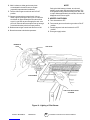
A. Determine how you wish to install the vent based on
the construction of the building and your personal
preference. (i.e., do you wish the flanged (finished)
side on the interior or the exterior of the building or
do you want two vents so that both exterior and
interior will be finished?) If needed, order an
additional vent from the factory. Our address and toll
free phone number are on the rear cover of this
manual. Install the vent as follows:
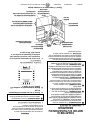
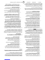
1. See Figure 3 for dimensions and information on
the vent.
2. Select a place as high above the heater as
possible in accordance with the above require-
ments and ensure that the vent or vents will not
contact or interfere with existing building sys-
tems (i.e., ducts, wiring, plumbing, etc.)
3. Place the unfinished side of the vent against the
wall in its elected location and trace its dimen-
sions on the wall with a pencil or other suitable
marker.
4. Cut or otherwise open a hole in the wall, or walls
for finished buildings, having the dimensions of
the unfinished side of the vent.
5. Install the vent or vents as desired and retain
with 4 suitable fasteners through the predrilled
holes in vent flange.
6Installation instructions and Owner’s Manual
Model # MH25NG/LP HS25NG/LP

B. Prepare to install the heater wall mounting bracket
as follows:
1. If the wall mounting bracket is to be attached to
a stud and wallboard wall, refer to Figure 3 for
dimensions, locate a stud, and drill two 1/8" pilot
holes into the stud centerline. Use template for
simplified installation.
2. If the wall mounting bracket is to be attached to
a brick or masonry wall, refer to Figure 3 for
dimensions. Obtain two 1/4 inch (inside
diameter)expansion anchors and determine the
correct drill size to be used with them. Drill
the appropriate size holes in the brick or ma-
sonry to accept the anchors.
C. Place the wall mounting bracket on the wall and
align the two through holes on the bracket with the
pilot holes or anchors. Install 1/4 inch by 2-1/2 inch
lag screws through the bracket into the stud or
anchors. Tighten securely.
D. Locate heater mounting clip on back of heater and
select the 1/4" – 20 by 3/4" hex head bolt and 1/4" -
20 hex nut.
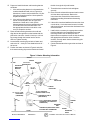
E. Position the heater as shown in Figure 3 and slide
the heater mounting clip over the bracket and install
CEILING
HEATER
24” MIN
9”
58”
FLOOR
THERMOSTAT (SEE INSTRUCTIONS
INCLUDED WITH THERMOSTAT
#6 X 1” SHEET METAL SCREWS
(2 REQUIRED - INCLUDED WITH
THERMOSTAT)
THERMOSTAT CABLE
(SEE FIGURE 4)
1/4” X 2-1/2” LONG
LAG SCREWS
(2 REQUIRED)
GAS
CONTROL
VALVE
1/2” NPT GAS INLET
(DO NOT EXCEED 1/2 PSI)
HEATER
REFLECTOR
FLUE
DEFLECTOR
1/4”-20x3/4”
HEXHEAD BOLT
MOUNTING
CLIP
1/4”-20
HEX NUT
HEATER WALL
MOUNTING
BRACKET
PREDRILLED
HOLES
FINISHED
SIDE
UNFINISHED
SIDE
FLANGE
the bolt through the clip and bracket.
F. Thread the hex nut onto the bolt and tighten
securely.
G. Ensure that the selected thermostat location meets
all of the above requirements. Refer to the
instructions that come with the thermostat for
additional grounding information and mounting
instruction.
H. If the wall is of stud and wallboard construction, then
use the #6 by 1 inch sheet metal screws, included
with the thermostat, and mount the thermostat in the
selected location.
I. If wall is brick or masonry, the appropriate anchors
must be obtained to accommodate thermostat
mounting screws. Use the back plate of the
thermostat as a template to mark the hole locations,
drill appropriate size anchor holes, install the
anchors, securely attach the thermostat using the
mounting screws.
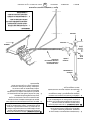
J. Connect thermostat wires to gas valve as shown in
Figure 4.
Figure 3. Heater Mounting Information
7Installation instructions and Owner’s Manual
Model # MH25NG/LP HS25NG/LP

LEAVE 2 THREADS BARE
USE MODERATE AMOUNT OF PIPE DOPE
3/4” MAXIMUM
THREAD LENGTH
1/2” BLACK PIPE
GAS VALVE BODY
1/2” MAXIMUM
DEPTH OF INSERTS
INTO GAS VALVE
Refer to National Electrical Code NFPA70-1993 and for
Canadian installations to current CODE C22.1-
3. CONNECTING HEATER TO GAS SUPPLY
WARNING: Depending on local codes and require-
ments and the installer’s skill level, the sizing and
installation of gas lines required to safely and efficiently
supply the heater may require the assistance of a
professional. If in doubt as to these requirements,
discuss the requirements of this manual with the dealer
from whom the heater was purchased and your gas
supplier.
3.1 Gas Supply Requirements
•See Tables 1 and 2 for gas supply minimum,
maximum, operating, and manifold pressures for
both heater models. Pressures are provided in
inches of W.C. (water column). Also, see heater
rating plates located on the heater.
WARNING: Model MH/HS25NG is designed to burn
natural gas and it comes equipped with a regulator. The
regulator is built into the gas valve. The maximum inlet
pressure to this regulator is 1/2 psi (14 in. W.C.) If gas
line pressure exceeds 1/2 psi, then an additional
regulator must be installed before the heater/regulator
to step down the pressure to a maximum of 1/2 psi.
•Most residential natural gas services provide a line
pressure of 4 oz. (6.9 in. W.C.). If in doubt consult
your natural gas supplier.
•To ensure the best performance from your natural
gas heater make sure the supply manifold pres-
sure is at least 6" W.C.
WARNING: Model MH/HS25LP is designed to burn
liquefied petroleum (LP) gas and it comes equipped
with a regulator. The regulator is built into the gas valve.
The maximum inlet pressure to this regulator is 1/2 psi
(14 in. W.C.). If gas line pressure exceeds 1/2 psi, then
an additional regulator must be installed before the
heater/regulator to step down the pressure to a maxi-
mum of 1/2 psi.
• To ensure the best performance from your LP gas
heater, make sure the supply manifold pressure is
at least 1/2 psi (14 in W.P.).
3.2 Piping Requirements
All piping installed must comply with local codes and
ordinances or with National Fuel Gas Code,
ANSI Z223.1 (NFPA 54), whichever takes precedence.
When installing piping, the following requirements must be
taken into consideration: Canadian installations must
comply with the B149.1.2 Gas Code.
•Use new properly reamed black pipe free from
chips.
•Apply a good quality pipe compound to all male
threads as shown in Figure 5 prior to assembly. If
LP gas is the fuel, ensure that pipe compound is
resistant to LP gas. Do not use Teflon™ tape.
Figure 5. Pipe Compound Application
•Male threads on pipe to be installed into gas valve
shall meet the requirements of Figure 6. Threads
longer than those shown in the figure may cause
gas valve distortion and malfunction.
•A sediment trap meeting the typical requirements
of Figure 7 shall be installed in the line to the gas
valve.
•A dedicated shutoff valve for the heater must be
installed in the gas supply line.
3.3 Piping Installation
While ensuring that all of the above gas supply require-
THERMOSTAT
POWERPILE GAS VALVE
POWERPILE GENERATOR
Figure 4. Connection Diagram
Figure 6. Gas Valve Connection Requirements
8Installation instructions and Owner’s Manual
Model # MH25NG/LP HS25NG/LP

ments and piping requirements are fulfilled, install piping
as follows:
A. In accordance with the above piping requirements,
assemble piping, sediment trap, shutoff valve, and
necessary fittings. Tighten all components securely.
WARNING: Failure to ensure that male threads on
pipe to be installed into gas valve meet the require-
ments of Figure 6 may cause gas valve damage,
distortion and malfunction.
B. Install a threaded nipple, prepared in accordance
with paragraph 3.2 into gas valve.
C. Connect gas piping to nipple installed in the gas
valve.
SUPPLY
LINE
SHUTOFF
VALVE
1/2”
TEE
3”
CAP
NIPPLE HEATER
RIGID PIPE WITH
UNION OR A FLEXIBLE
CONNECTOR TO HEATER
Figure 7. Typical Piping Installation
NOTE:
1. ONLY USE A PIPE COMPOUND
WHICH IS RESISTANT TO
LIQUIFIED GASES ON LP
INSTALLATIONS.
2. FITTINGS SHOWN ARE NOT
INCLUDED WITH HEATER.
WARNING: When testing gas piping use only a soap
and water solution. Do not use a match or other flame
for leak testing. If during leakage check gas is
smelled, turn off the gas supply and ventilate building.
D. Ensure the building is properly ventilated. Without
lighting the pilot light of the heater, open the gas
supply valve and pressurize the piping up to the
heater’s gas valve.
E. Using a brush, apply a soap and water solution to all
connections and look for bubbles indicating a leak. If
a leak is detected, turn off gas supply and tighten
connections. Retest and tighten connections until no
more leaks are found.
9Installation instructions and Owner’s Manual
Model # MH25NG/LP HS25NG/LP

MANUAL GAS
CONTROL KNOB
PILOTSTAT
POWER UNIT
PRESSURE
REGULATOR
ADJUSTMENT
STANDARD
PRESSURE
REGULATOR
PILOT GAS OUTLET
(PRESSURE TAPPING
DIRECTLY BENEATH)
PILOT FLOW ADJUSTING SCREW
(BENEATH COVER SCREW)
WRENCH
BOSS
GAS
INLET
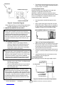
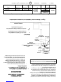
Figure 9. Gas Valve Components
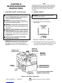
2. HEATER STARTUP
WARNING: During heater startup ensure that
building is well ventilated.
A. Open the gas supply valve or valves.
B. Set the thermostat to the OFF position.
See Figure 8.
C. If the manual gas control knob on the gas valve is
not in the OFF position, partially depress the knob
and rotate to the OFF position. See Figure 9.
CHAPTER III
HEATER OPERATING
INSTRUCTIONS
1. OPERATING SAFETY INSTRUCTIONS
WARNING: When used without fresh air, heater may
give off CARBON MONOXIDE, an odorless poison-
ous gas. OPEN WINDOW AN INCH OR TWO FOR
FRESH AIR WHEN USING HEATER.
WARNING: This heater is equipped with a PILOT
LIGHT SAFETY SYSTEM. DO NOT TAMPER WITH
PILOT LIGHT SAFETY SYSTEM.
WARNING: If heater shuts off, do not relight until you
provide fresh air. Open door for 5 minutes. If heater
keeps shutting off, have it serviced. Keep burner and
control clean.
WARNING: CARBON MONOXIDE POISONING MAY
LEAD TO DEATH. Early signs of carbon monoxide
poisoning resemble the flu with headache, dizziness
and/or nausea. If you have these signs, heater may
not be working properly. Get fresh air at once! Have
heater serviced.
WARNING: DO NOT USE MATCH OR OTHER
FLAME FOR LEAK TESTING.
CAUTION: If the infra-red color of the grid becomes
dull when the building furnace is operating, consult
gas supplier on correct gas supply piping sizes.
CAUTION: This heater is for indoor installation only!
NOTE
Gasket binder material used in this heater assembly
will temporarily emit an odor and/or vapor. This condi-
tion will clear up in approximately 20 minutes and
thereafter will not reoccur. Refer to Chapter 2 for
ventilation.
FIGURE 8. THERMOSTAT CONTROLS
10 Installation instructions and Owner’s Manual
Model # MH25NG/LP HS25NG/LP

PILOT BURNER
LIGHT PILOT WITH MATCH
AS SHOWN
GAS VALVE
DEPRESS TO
LIGHT
D. Wait 5 minutes to allow gas that may have
accumulated in the main burner to escape
(especially important after installation).
E. Turn the manual gas control knob to the PILOT
position.
F. Depress the manual gas control knob. Using a
match, light the pilot light. See Figure 10. Hold the
knob down for approximately 30 seconds to allow
any air in gas lines to pass through pilot and, once
pilot is lit, allow the thermocouple to heat up enough
to activate the safety valve in an open position.
G. Release manual gas control knob and turn to ON.
H. Reset thermostat to desired temperature.
NOTE
During the initial startup of heater, an odor and,
perhaps, some vapor will come from the heater. This
is the gasket binding material emitting this odor and/
or vapor. After approximately 20 minutes, this odor will
disappear and not occur again.
3. HEATER SHUTDOWN
A. Turn thermostat to OFF.
B. Turn manual gas control knob on gas valve to PILOT
position.
C. Partially depress knob and rotate to the OFF
position.
D. Close gas supply valves.
Figure 10. Lighting of Pilot Burner
11 Installation instructions and Owner’s Manual
Model # MH25NG/LP HS25NG/LP

CHAPTER IV
OPERATOR MAINTENANCE
INSTRUCTIONS
1. TROUBLESHOOTING
A. Table 4 lists the common malfunctions which you may
find during the operation or maintenance of your heater.
B. For additional information, refer to Honeywell Field
Bulletin enclosed in the heater carton.
C. In the event results cannot be obtained after performing
all listed solutions, call the factory.
2. ADJUSTING THE PILOT FLAME
The pilot flame should envelop 3/8 to 1/2 in. (10 to 13
mm) of the tip of the thermocouple or generator.
Refer to Figure 11. To adjust:
MANUAL GAS
CONTROL KNOB
WRENCH
BOSS
GAS
INLET
PILOTSTAT
POWER UNIT
PRESSURE REGULATOR ADJUSTMENT
(BENEATH COVER SCREW)
PILOT FLOW ADJUSTING SCREW
(BENEATH COVER SCREW)
INSTALL LONG
SCREW IN
OUTSIDE CORNER
PILOT GAS OUTLET
(PRESSURE TAPPING
DIRECTLY BENEATH)
STANDARD
PRESSURE
REGULATOR
(“A” MODEL)
STEP OPENING REGULATOR
(“C” MODEL)
Figure 12. Top View of Standard Capacity Gas Control
3/8 TO 1/2 INCH
(10-13 MILLIMETERS)
THERMOCOUPLE
PROPER FLAME
ADJUSTMENT
Figure 11. Proper Flame Adjustment
A. Remove pilot adjustment cover screw. Refer to
Figure 12.
B. Turn inner adjustment screw clockwise to
decrease or counterclockwise to increase
pilot flame.
C. Always replace cover screw after adjustment and
tighten firmly to ensure proper operation.
12 Installation instructions and Owner’s Manual
Model # MH25NG/LP HS25NG/LP

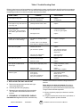
Table 4. Trouble Shooting Chart
Below in chart form are various symptoms of a malfunctioning system, possible defects that will cause these symptoms
and suggested corrective measures. The chart assumes that the proper gas pressure is available to the heater and that
the lighting procedure is as stated on the plate attached to the heater.
SYMPTOMS CAUSES SOLUTIONS
burner light off very slow partially block pilot orifice replace
pilot out of adjustment re-adjust pilot
burner light off very slow infra-red partially blocked burner orifice replace
color stays dull
burner flash back low gas pressure correct line pressure
(roaring noise during operation or call your gas supplier
and ceramic grid surface will be
dark) damaged burner replace
ceramic grid or burner sooting up first check for damaged burner replace if damaged
(when new or after cleaning) orifice
if burner orifice is not damaged replace
then check for damaged manifold
pilot cannot be ignited blocked pilot orifice replace
gas cock not in position gas cock knob must be
turned to pilot and held
depressed
pilot gas flow adjustment open and adjust
screw may be closed (see Figure 12)
pilot lights but goes out defective thermocouple replace
defective control replace
pilot stays lit but main burner loose wire or improperly wired tighten connections, check
will not light wiring diagram
defective control replace
blocked burner orifice clean orifice or replace
failure to ignite main gas off open manual valves
air in gas line bleed gas line
loose wire connections tighten wire connections
dirty wire connections clean terminals and secure
terminals
3. REPLACING THE GAS VALVE UNIT
A. Remove the two gas valve unit wires at the gas
control valve labeled “PP”.
B. Unscrew gas valve from gas piping.
C. Reconnect gas valve and unit wires to terminals
“PP”. Be sure to leave thermostat wire on one
terminal.
4. FREQUENCY OF OPERATOR CHECKS
Intermittent use. Appliances that are used seasonally
should be checked before shutdown and again before the
next use.
Dusty, wet or corrosive environment. Since these
environments can cause the gas control to deteriorate
more rapidly, the system should be checked more often.
The gas control should be replaced if:
A. It does not perform properly on checkout or trouble
shooting.
B. The gas control knob Is hard to turn or push down, or
it fails to pop back up when released.
13 Installation instructions and Owner’s Manual
Model # MH25NG/LP HS25NG/LP

IF SERVICE IS REQUIRED
PLEASE DO NOT RETURN THIS APPLIANCE TO YOUR STORE
For information regarding service, please call our Toll-Free Number:
1-800-251-0001.
Our office hours are 8:30 AM – 5:00 PM, Eastern Time Zone
Monday through Friday
Please include the model number, date of purchase, and description of
problem in all communication.
CHAPTER V
REPLACEMENT PARTS LIST
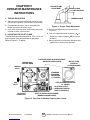
1.INTRODUCTION
This section of the manual will help you to obtain
efficient and dependable service from your heater and
enable you to order repair parts correctly.
A. Order parts by giving full model number and serial
number as it is stated on the name place attached
to the heater.
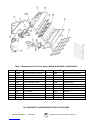
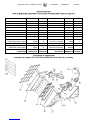
B. See Figure 13 to assist in locating parts.
C. Refer to Table 5 for part number and description.
2.WARRANTY
Enerco Group, Inc. warrants that Infra-Red Heaters
manufactured and sold will be free from defects in
material and workmanship.
Parts, assemblies, controls, etc. furnished by EGI
suppliers will carry a one (1) year warranty from date of
purchase.
The sole responsibility of EGI under this warranty shall be
to replace any part for which a written claim is made to
EGI WITHIN THE TIME LIMIT OF THIS WARRANTY,
WHICH IS RETURNED UPON REQUEST TO EGI –
F.O.B. Cleveland, Ohio – OR F.O.B. an EGI authorized
service facility and which is proved to be defective upon
inspection by EGI.
This warranty shall not apply to any part or product which
has been subjected to misuse or neglect, damaged by
accident, or rendered defective by reason of improper
installation. THIS WARRANTY IS IN LIEU OF ANY AND
ALL OTHER WARRANTIES, EXPRESSED OR IMPLIED,
and of any other responsibility of EGI for parts or products
sold by EGI, including consequential or special damages.
14 Installation instructions and Owner’s Manual
Model # MH25NG/LP HS25NG/LP

7
6
5
15
4
14
13
10
17
16
22
21
8
20
11 12
13
19 18
2
9
23
Table 5. Replacement Parts List for Heater Models MH/HS25NG and MH/HS25LP
ITEM NO. STOCK NO. DESCRIPTION ITEM NO. STOCK NO. DESCRIPTION
1 02529A Burner Assembly Complete 12 05455 Orifice-Burner-Propane Gas
2 00377A Reflector Assembly 13 05576 Orifice-Pilot-Natural Gas
3 01357 Flue Deflector 14 05573 Orifice-Pilot-Propane Gas
4 16451 Pilot Tube 15 10358 Thermostat Cable
5 00024 Gas Valve-Natural Gas 16 11406 Pilot Burner N/G
6 00025 Gas Valve-Propane Gas 17 11405 Pilot Burner L/P
7 10367 Thermostat 18 04435A Grid Replacement
8 14405 Wall Mounting Bracket 19 12369 Gasket
9 04432 Face Guard 20 05354 Jamb Nut
10 09360 Thermocouple/Generator 21 05351 Connector
11 05445 Orifice-Burner-Natural Gas 22 98593 3/8” Close Nipple
23 19014 Intake Louver
ALL WARRANTY CLAIMS REQUIRE PROOF OF PURCHASE
15 Installation instructions and Owner’s Manual
Model # MH25NG/LP HS25NG/LP

ANSI Z83.6b-1993
ENERCO GROUP, INC., 4560 W. 160TH ST., CLEVELAND, OHIO 44135
216-916-3000 Toll Free Number 1-800-251-0001
www.mrheater.com
Mr. Heater is a registered trademark of Enerco Group, Inc.
© 2005, Enerco/Mr. Heater. All rights reserved
WARRANTY INFORMATION
Keep this warranty
Model ______________________
Serial No. ___________________
Date Purchased _______________
Always specify model and serial numbers when communication with the factory.
We reserve the right to amend these specifications at any time without notice. The only warranty applicable
is our standard written warranty. We make no other warranty, expressed or implied.
Enerco Group, Inc. warrants this product to be free from defects in materials and components for two (2)
years from the date of first purchase, provided that the product has been properly installed, operated and
maintained in accordance with all applicable instructions. To make a claim under this warranty the Bill of
Sale or cancelled check must be presented.
The warranty is extended only to the original retail purchaser. This warranty covers the cost of part(s)
required to restore the heater to proper operating condition and an allowance for labor when provided by an
Enerco Group, Inc. Authorized Service Center. Warranty part(s) MUST be obtained through authorized
dealers of this product and/or Enerco Group, Inc. who will provide original factory replacement parts. Failure
to use original factory parts voids this warranty. The heater MUST be installed by a qualified installer in
accordance with all local codes and instructions furnished with the unit.
This warranty does not apply to parts that are not in original condition because of normal wear and tear of
parts that fail or become damaged as a result of misuse, accidents, lack of proper maintenance or defects
caused by improper installation. Travel, diagnostic cost, labor, transportation and any and all such costs
related to repairing a defective heater will be the responsibility of the owner.
TO THE FULL EXTENT ALLOWED BY THE LAW OF THE JURISDICTION THAT GOVERNS THE SALE
OF THE PRODUCT; THIS EXPRESS WARRANTY EXCLUDES ANY AND ALL OTHER EXPRESSED
WARRANTIES AND LIMITS THE DURATION OF ANY AND ALL IMPLIED WARRANTIES OF MERCHANT-
ABILITY AND FITNESS FOR A PARTICULAR PURPOSE, TO TWO (2) YEARS OF ALL COMPONENTS
FROM THE FIRST DATE OF PURCHASE; AND ENERCO GROUP, INC.’S LIABILITY IS HEREBY LIMITED
TO THE PURCHASE PRICE OF THE PRODUCT AND ENERCO GROUP, INC. SHALL NOT BE LIABLE
FOR ANY OTHER DAMAGES WHATSOEVER INCLUDING INDIRECT, INCIDENTAL OR CONSEQUEN-
TIAL DAMAGES.
Some states do not allow a limitation on how long an implied warranty lasts or an exclusion or limitation on
incidental or consequential damages, so the above limitation on implied warranties, or limitation on dam-
ages, may not apply to you.
This warranty gives you specific legal rights, and you may also have other rights that very from state to
state. Always specify model and serial number when communication with the factory.
CAN 1-2.16-M81
®
16 Installation instructions and Owner’s Manual
Model # MH25NG/LP HS25NG/LP

ANSI Z83.6b-1993
ENERCO GROUP, INC., 4560 W. 160TH ST., CLEVELAND, OHIO 44135
216 916-3000 Numéro sans frais 1 800 251-0001
www.mrheater.com
Mr. Heater est une marque déposée d’Enerco Group, Inc.
© Enerco/Mr. Heater, 2005. Tous droits réservés.
RENSEIGNEMENTS SUR LA GARANTIE
Conservez cette garantie
Modèle ______________________
Numéro de série ___________________
Date de l’achat _______________
Précisez toujours le modèle et le numéro de série dans vos communications avec l’usine.
Nous nous réservons le droit de modifier ces spécifications en tout temps sans préavis. La seule garantie
applicable est notre garantie écrite standard. Nous n’offrons aucune autre garantie, expresse ou implicite.
Enerco Group, Inc. garantit ce produit contre tout défaut de matériel et de fabrication pour une période de
deux (2) ans à partir de la date de l’achat initial, à la condition que ce produit ait été correctement installé,
utilisé et entretenu conformément aux directives applicables. Pour faire une réclamation en vertu de cette
garantie, un contrat de vente ou un chèque annulé doit être présenté.
La garantie ne protège que l’acheteur initial auprès du détaillant. Cette garantie couvre le coût de la ou des
pièces requises pour rétablir le bon fonctionnement du radiateur et, s’il y a lieu, celui de la main-d’œuvre du
centre de réparations autorisé par Enerco Group, Inc.. Les pièces garanties DOIVENT être obtenues
auprès des détaillants autorisés de ce produit et/ou d’Enerco Group, Inc., qui fournira les pièces de
rechange originales de l’usine. Le défaut d’utiliser des pièces originales de l’usine aura pour effet d’annuler
cette garantie. Le radiateur DOIT être installé par un installateur qualifié conformément à tous les codes
locaux et à la notice d’installation fournie avec l’appareil.
Cette garantie ne s’applique pas aux pièces soumises à une usure normale ni aux pièces défectueuses
ou endommagées en raison d’un usage abusif, d’un accident, ou bien d’un entretien inadéquat ou d’une
mauvaise installation. Les frais de déplacement, de diagnostic, de main-d’œuvre et de transport, ainsi que
toutes les dépenses reliées à la réparation d’un radiateur défectueux seront à la charge du propriétaire.
AVEC TOUTE LA RIGUEUR DE LA LOI DU TERRITOIRE GOUVERNANT LA VENTE DU PRODUIT,
CETTE GARANTIE EXPRESSE EXCLUT TOUTE AUTRE GARANTIE EXPRESSE ET LIMITE LA DURÉE
DE TOUTES LES GARANTIES IMPLICITES DE QUALITÉ MARCHANDE ET D’APTITUDE À L’USAGE À
DEUX (2) ANS POUR TOUS LES COMPOSANTS À PARTIR DE LA DATE DU PREMIER ACHAT; ET LA
RESPONSABILITÉ D’ENERCO GROUP, INC. EST PAR LA PRÉSENTE LIMITÉE AU PRIX D’ACHAT DU
PRODUIT; ENERCO GROUP, INC. NE SERA RESPONSABLE D’AUCUN AUTRE DOMMAGE INDIRECT,
ACCESSOIRE OU CONSÉCUTIF.
Certaines province ou certains États ne permettent pas une limite de durée de garantie implicite ni une
exclusion ou une limitation sur les dommages accessoires et consécutifs; ainsi, il est possible que la limite
ci-dessus sur les garanties implicites ou sur les dommages ne s’applique pas à vous.
La présente garantie vous accorde des droits juridiques précis, et vous pourriez également avoir d’autres
droits qui varient selon la province ou l’État. Précisez toujours le modèle et le numéro de série dans vos
communications avec l’usine.
CAN 1-2.16-M81
®
16 Notice d’installation et guide d’utilisation
Modèle n° MH25NG/LP HS25NG/LP

7
6
5
15
4
14
13
10
17
16
22
21
8
20
11 12
13
19 18
2
9
23
Tableau 5 Liste des pièces de remplacement pour les modèles de radiateurs
MH/HS25NG et MH/HS25LP
N° D’ARTICLE N° DE NOMEN- DESCRIPTION N° D’ARTICLE N° DE NOMEN- DESCRIPTION
CLATURE CLATURE
1 02529A Ensemble complet de 12 05455 Orifice-brûleur-gaz propane
brûleur
2 00377A Ensemble de réflecteur 13 05576 Orifice-veilleuse-gaz naturel
3 01357 Déflecteur de gaz de 14 05573 Orifice-veilleuse-gaz propane
combustion
4 16451 Tube de veilleuse 15 10358 Câble du thermostat
5 00024 Soupape de gaz-gaz 16 11406 Veilleuse GN naturel
5 00024 Soupape de gaz-gaz 16 11406 Veilleuse GN naturel
7 10367 Thermostat 18 04435A Grille de rechange
8 14405 Support mural 19 12369 Joint d’étanchéité
9 04432 Grille de protection 20 05354 Contre-écrou
10 09360 Thermocouple/générateur 21 05351 Connecteur
11 05445 Orifice-brûleur-gaz naturel 22 98593 Raccord simple 3/8 po
23 19014 Évent à lames
TOUTES LES RÉCLAMATIONS EN VERTU DE LA GARANTIE REQUIÈRENT UNE
PREUVE D’ACHAT
Notice d’installation et guide d’utilisation
Modèle n° MH25NG/LP HS25NG/LP 15

SI UNE RÉPARATION EST NÉCESSAIRE
NE RETOURNEZ PAS CET APPAREIL À VOTRE MAGASIN
Pour plus de renseignements sur les réparations, veuillez appeler notre
numéro sans frais : 1 800 251-0001.
Nos heures d’ouverture sont de 8 h 30 à 17 h, HE,
du lundi au vendredi
Veuillez inclure le numéro de modèle, la date de l’achat et la description du
problème dans toutes vos communications.
CHAPITRE V
LISTE DES PIÈCES DE RECHANGE
1. INTRODUCTION
La présente section du manuel vous aidera à obtenir un
rendement fiable et efficace de votre radiateur et à
commander les pièces correctement.
A. Pour commander les pièces, indiquez le numéro
complet du modèle et le numéro de série indiqués
sur la plaque signalétique du radiateur.
B. Consultez la figure 13 pour repérer les pièces.
C. Reportez-vous au tableau 5 pour le numéro et la
description des pièces.
2. GARANTIE
Enerco Group, Inc. garantit les radiateurs à infrarouge
fabriqués et vendus contre les défauts de matériel et de
fabrication.
Les pièces, les ensembles, les commandes, etc.,
fournis par les fournisseurs d’EGI comportent une
garantie d’un (1) an à partir de la date d’achat.
En vertu de cette garantie, la seule responsabilité d’EGI
consiste à remplacer toute pièce pour laquelle une
réclamation écrite est soumise à EGI DURANT LA
PÉRIODE DE GARANTIE, CETTE PIÈCE DEVANT
ÊTRE RETOURNÉE SUR DEMANDE À EGI – FOB à
Cleveland, en Ohio – OU FOB à un centre de réparations
EGI autorisé, si EGI détermine après inspection que la
pièce est défectueuse.
Cette garantie ne protège aucunement une pièce ou
un produit négligés ou dont on a fait un usage abusif,
accidentellement endommagés ou défectueux en
raison d’une mauvaise installation. CETTE GARANTIE
REMPLACE TOUTE AUTRE GARANTIE EXPRESSE OU
IMPLICITE, et toute autre responsabilité d’EGI en regard
des pièces ou des produits vendus par EGI, incluant les
dommages consécutifs ou spéciaux.
14 Notice d’installation et guide d’utilisation
Modèle n° MH25NG/LP HS25NG/LP

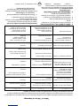
Tableau 4. Tableau de dépannage
Le tableau suivant présente différents symptômes d’un système défectueux, les causes possibles de ces symptômes et
les mesures correctives suggérées. Le tableau suppose que la pression du gaz combustible est appropriée et que la
procédure d’allumage est conforme à celle indiquée sur la plaque rattachée au radiateur.
SYMPTÔMES CAUSES SOLUTIONS
allumage très lent de la veilleuse obturation partielle de l’orifice de la remplacer
veilleuse, veilleuse mal réglée régler de nouveau la veilleuse
allumage très lent de la veilleuse, obturation partielle de l’orifice de la remplacer
I la couleur de l’infrarouge veilleuse
demeure terne
retour de flamme du brûleur pression insuffisante du gaz corriger la pression dans la conduite
(fonctionnement bruyant du ou appeler le fournisseur en gaz
radiateur et la surface de la
grille en céramique est sombre)
brûleur endommagé remplacer
grille en céramique ou brûleur vérifier d’abord si l’orifice du brûleur remplacer si endommagé
noirs de suie (alors qu’ils sont est endommagé
neufs ou viennent d’être nettoyés) si l’orifice du brûleur n’est pas remplacer
endommagé vérifier si le collecteur
est endommagé
impossible d’allumer la veilleuse orifice de la veilleuse bloqué remplacer
robinet de gaz pas en position le bouton du robinet doit être
tourné à PILOT et tenu enfoncé
la vis de réglage du débit de gaz à ouvrir et régler
la veilleuse est peut-être fermée (voir la figure 12)
la veilleuse s’allume puis s’éteint thermocouple défectueux remplacer
commande défectueuse remplacer
la veilleuse demeure allumée fils de raccordement relâchés ou serrer les connexions, vérifier
mais le brûleur principale inadéquats mais le brûleur principal
ne s’allume pas le schéma de câblage
commande défectueuse remplacer
orifice du brûleur bloqué nettoyer l’orifice ou remplacer
allumage impossible gaz secteur coupé ouvrir les robinets manuels
air dans la conduite de gaz purger la conduite de gaz
fils de raccordement relâchés serrer les fils de raccordement
fils de raccordement encrassés nettoyer et serrer les bornes
3. REMPLACEMENT DE LA SOUPAPE DE GAZ
A. Déposez les deux fils étiquetés «PP» à la soupape
de gaz.
B. Dévissez la soupape de gaz du tuyau.
C. Reconnectez la soupape de gaz et les fils de la
soupape aux bornes «PP». Assurez-vous de laisser
le fil du thermostat sur une borne.
4. FRÉQUENCE DES INSPECTIONS PAR
L’UTILISATEUR
Usage intermittent. Les appareils utilisés sur une base
saisonnière doivent être inspectés avant leur mise à l’arrêt
et avant leur mise en fonction à la saison suivante.
Environnement poussiéreux, humide ou corrosif.
Puisque ce type d’environnement peut entraîner une
détérioration rapide de la commande de gaz, le système
doit être inspecté plus souvent.
La commande de gaz doit être remplacée si :
A. Elle ne fonctionne pas correctement lors de
l’inspection ou du dépannage.
B. Il est difficile de tourner ou d’enfoncer le bouton
de la commande de gaz, ou si le bouton ne
remonte pas lorsque relâché.
Notice d’installation et guide d’utilisation
Modèle n° MH25NG/LP HS25NG/LP 13
La page est en cours de chargement...
La page est en cours de chargement...
La page est en cours de chargement...
La page est en cours de chargement...
La page est en cours de chargement...
La page est en cours de chargement...
La page est en cours de chargement...
La page est en cours de chargement...
La page est en cours de chargement...
La page est en cours de chargement...
La page est en cours de chargement...
La page est en cours de chargement...
-
 1
1
-
 2
2
-
 3
3
-
 4
4
-
 5
5
-
 6
6
-
 7
7
-
 8
8
-
 9
9
-
 10
10
-
 11
11
-
 12
12
-
 13
13
-
 14
14
-
 15
15
-
 16
16
-
 17
17
-
 18
18
-
 19
19
-
 20
20
-
 21
21
-
 22
22
-
 23
23
-
 24
24
-
 25
25
-
 26
26
-
 27
27
-
 28
28
-
 29
29
-
 30
30
-
 31
31
-
 32
32


Mr. Heater HeatStar HS25NG Manuel utilisateur
- Catégorie
- Chauffe-eau
- Taper
- Manuel utilisateur