Modern Forms WS-65023 Ember Mode d'emploi
- Taper
- Mode d'emploi

• Read all instructions before installing.
• System is intended for installation by a licensed electrician in accordance with the National Electrical Code (NEC) and local regulations.
• When handling the xture, do not apply pressure to the LEDs. Hold the xture by the base only.
• Retain installation instructions for future maintenance reference.
All parts must be used as indicated in these instructions. This product is designed for use only with the supplied parts and/or
accessories designated for use by Modern Forms. Substitution of parts or accessories not designated for use with this product by Modern
Forms could result in personal injury or property damage, and will void the warranty. Contact an authorized dealer or the manufacturer if any
parts are damaged or missing.
Coastal conditions may cause mineral and residue build-up on the xture. We recommend that customers in coastal
areas clean all external surfaces of the xture once every two weeks with a wet cloth.
Pour éviter tout choc électrique, assurez-vous que le disjoncteur soit mis hors tension avant de commencer.
• Lisez toutes les instructions avant l’installation.
• Le système doit être installé par un électricien licensié conformément au code national de l’électricité (NEC), et également aux
règlements locaux.
• Lors de la manipulation du luminaire, n’appuyez pas sur les LED. Tenez-le uniquement par la base.
Toutes les pièces doivent être utilisées comme indiqué dans ces instructions. Ce produit est conçu pour être utilisé seulement
avec les pièces et/ou accessoires fournis pour être utilisés avec les produits Modern Forms. Remplacer des pièces ou accessoires non conçus
pour ce produit Modern Forms pourrait causer des dommages corporels ou matériels et pourrait également causer l’annulation de la
garantie. Veuillez contacter un revendeur autorisé ou le fabricant si des pièces manquent ou sont endommagées.
Les conditions côtières peut causer une accumulation de minéraux et de résidue sur le luminaire. Nous recommendons
aux clients qui resident dans les zones côtières de nettoyer toutes les surfaces externes du luminaire une fois toutes les deux semaines avec
un chion humide.
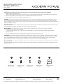
WireConnector
Qty: 3pcs+1Extra
Mounting Screw
Qty:1 Extra
Assembly Screw
Qty: 2+1 Extra Conversion Plate
Qty:1 pc
Mounting Ring
Qty:1 pc
A B CDE
1
INSTALLATION INSTRUCTIONS
WS-65023
Phone (800) 526.2588
Fax (800) 526.2585
44 Harbor Park Drive
Port Washington, NY 11050
1600 Distribution Ct
Lithia Springs, GA 30122
1750 Archibald Avenue
Ontario, CA 91760

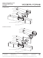
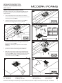
Fixture
Mounting Screw
Switch Box
Mounting Plate
B
Switch Box Screw
Wire Connector
A
Driver 5 5/16"Lx2 9/16"W x5/8"H
2
INSTALLATION INSTRUCTIONS
WS-65023
Phone (800) 526.2588
Fax (800) 526.2585
44 Harbor Park Drive
Port Washington, NY 11050
1600 Distribution Ct
Lithia Springs, GA 30122
1750 Archibald Avenue
Ontario, CA 91760
Mounting Screw
Junction Box
Mounting Plate
B
Assembly Screw
Wire Connector
A
Fixture
Driver 5 5/16"Lx2 9/16"W x5/8"H
Mounting Ring
Conversion Plate
Junction Box Screw
D
E
C

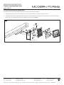
4. Connect the driver’s input wires to switch box wires as shown in , making sure that all wire connectors (A) are secured. If your outlet
the mounting plate using the screw provided. After wires are connected,tuck them carefully inside the switch box.
5. Secure the mounting plate to the switch box using standard switch box screws that comes with the switch box.
(i)using any other non-original-manufacturer provided switch box screw may result in safty issue;
(ii) The side of the mounting plate marked “GND” must face out.
4. Connect the driver’s input wires to junction box wires as shown in , making sure that all wire connectors (A) are secured. If your outlet
the mounting plate using the screw provided. After wires are connected,tuck them carefully inside the junction box.
5. Secure the mounting ring(D) to the junction box using standard junction box screws that comes with the junction box. Secure the mounting
plate and conversion plate(E) to the mounting ring(D) with assembly screw(C).
(i)using any other non-original-manufacturer provided junction box screw may result in safty issue;
(ii) The side of the mounting plate marked “GND” must face out.
information.
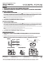
8. To utilize ELV or TRAIC dimming: use wires black (hot), white (neutral) and bare copper ground wire (ground).
9. To utilize 0-10V dimming: use wire purple (dim+), pink or gray (dim-), black (hot), white (neutral) and bare copper ground wire (ground).
Ø4"
1 3/4"
GND
1 3/8"
4 1/2"
1 5/8"
8"
1 3/8"
Black or
Smooth
White or
Ribbed
Bare wire
(Ground)
Black
(Hot)
White
(Neutral)
Green or Bare Copper
(Ground)
White - Neutral
Black - Hot
Purple - Dim+
Pink or Gray - Dim-
Red - Fixture+
Black - Fixture-
3
INSTALLATION INSTRUCTIONS
WS-65023
Phone (800) 526.2588
Fax (800) 526.2585
44 Harbor Park Drive
Port Washington, NY 11050
1600 Distribution Ct
Lithia Springs, GA 30122
1750 Archibald Avenue
Ontario, CA 91760
5 3/4"
2 3/4"
1 3/8"
1 5/8"

1Modern Forms retains the right to modify the design of our products at any time as part of the company's continuous improvement program. JAN 2023 G0
modernforms.com
Phone (800) 526.2588
Fax (800) 526.2585
Headquarters/Eastern Distribution Center
44 Harbor Park Drive
Port Washington, NY 11050
Central Distribution Center
1600 Distribution Ct
Lithia Springs, GA 30122
Western Distribution Center
1750 Archibald Avenue
Ontario, CA 91760
INSTALLATION INSTRUCTION
Trimless Junction Box Cover
MKCP-3040-WT
OVERALL COMPONENT DIMENSIONS
CAUTION: TO PREVENT ELECTRICAL SHOCK, ENSURE ELECTRICITY HAS BEEN TURNED OFF AT THE CIRCUIT BREAKER BEFORE
BEGINNING.
-Read all instructions before installing.
-System is intended for installation by a licensed electrician in accordance with the National Electrical Code (NEC) and local regulations.
-When handling the xture, do not apply pressure to the LEDs. Hold the xture by the base only.
-Retain installation instructions for future maintenance reference.
WARNING: All parts must be used as indicated in these instructions. This product is designed for use only with the supplied parts and/or
accessories designated for use by Modern Forms. Substitution of parts or accessories not designated for use with this product by Modern Forms
could result in personal injury or property damage, and will void the warranty. Contact an authorized dealer or the manufacturer if any parts are
damaged or missing.
MISE EN GARDE: POUR ÉVITER TOUT CHOC ÉLECTRIQUE, ASSUREZVOUS QUE LE DISJONCTEUR SOIT MIS HORS TENSION AVANT DE
COMMENCER.
-Lisez toutes les instructions avant l’installation.
-Le système doit être installé par un électricien licensié conformément au code national de l’électricité (NEC), et également aux règlements
locaux.
-Lors de la manipulation du luminaire, n’appuyez pas sur les LED. Tenez-le uniquement par la base.
ATTENTION: Toutes les pièces doivent être utilisées comme indiqué dans ces instructions. Ce produit est conçu pour être utilisé seulement avec
les pièces et/ou accessoires fournis pour être utilisés avec les produits Modern Forms. Remplacer des pièces ou accessoires non conçus pour ce
produit Modern Forms pourrait causer des dommages corporels ou matériels et pourrait également causer l’annulation de la garantie. Veuillez
contacter un revendeur autorisé ou le fabricant si des pièces manquent ou sont endommagées.
COMPONENT OVERVIEW
The trimless junction box cover is intended for installation to NEC approved 4” square junction boxes recessed in drywall and ush with the
support structure. It may be covered with spackle and/or plaster to conceal junction box visibility. It is to be connected to compatible Modern
Forms xtures. Refer to specications sheets for more information.
2"
#8
TYP
HARDWARE
Wire Connector
Qty: 3 (+1 Extra)
½” Plastic Spacer
Qty: 2
⁄”-40 x 1⁄” Long
Mounting Screw
Qty: 2 (+1 Extra)
¾” Plastic Spacer
Qty: 2
A
D
B
E
#8-32 x ¾” Long
Junction Box Screw
Qty: 2 (+1 Extra)
1” Plastic Spacer
Qty: 2
C
F
NOTE: This accessory is supplied with an optional mounting C-ring for
xture connection via ⁄” K.O. hole. This component may be omitted
from the installation if mounting xtures using #8 screw holes.

2Modern Forms retains the right to modify the design of our products at any time as part of the company's continuous improvement program. JAN 2023 G0
modernforms.com
Phone (800) 526.2588
Fax (800) 526.2585
Headquarters/Eastern Distribution Center
44 Harbor Park Drive
Port Washington, NY 11050
Central Distribution Center
1600 Distribution Ct
Lithia Springs, GA 30122
Western Distribution Center
1750 Archibald Avenue
Ontario, CA 91760
INSTALLATION INSTRUCTION
Trimless Junction Box Cover
MKCP-3040-WT
FIG. 1
FIG. 2
FIG. 4
TRIMLESS JUNCTION BOX COVER INSTALLATION:
The trimless junction box cover is compatible with NEC approved
4” square junction boxes recessed in drywall and ush with the
support structure.
1. Install compatible junction box (by others) to the framing
structure. Ensure the junction box is ush with the base or front
of framing structure (See FIG. 1).
2. Install the mounting plate to the junction box (See FIG. 2).
Ensure the spacer alignment base is facing outward.
FIG. 3
105mm
105mm
FIG. 5 FIG. 6
3. Determine the drywall thickness and select the appropriate
spacer to install between the mounting plate and the trimless
junction box cover (See FIG. 3).
NOTE: Only 1 matching pair of spacers are to be used per
installation.
4. Using the mounting screws provided, attach the trimless
junction box cover to the mounting plate (See FIG. 4).
5. Make a 4⁄” square cutout in drywall at the intended trimless
junction box cover location and proceed to install to framing
structure (See FIG. 5). Apply and nish spackle up to the center
hole of trimless junction box cover. Ensure #8 holes on the
cover are free of spackle. (See FIG. 6).
Mounting Plate
Plastic
Spacers
Trimless Junction Box Cover
Cover Mounting Screws
Ground Wire
Example: ½” Drywall (No Spacer)
⁄”½”
Spacer Alignment
Base
Spacer
Height
Drywall
Thickness
No Spacer ½”
½” ⁄”
¾” 1”
1” 1¼”
Junction Box
Screws
CB
D
E
F

3Modern Forms retains the right to modify the design of our products at any time as part of the company's continuous improvement program. JAN 2023 G0
modernforms.com
Phone (800) 526.2588
Fax (800) 526.2585
Headquarters/Eastern Distribution Center
44 Harbor Park Drive
Port Washington, NY 11050
Central Distribution Center
1600 Distribution Ct
Lithia Springs, GA 30122
Western Distribution Center
1750 Archibald Avenue
Ontario, CA 91760
INSTALLATION INSTRUCTION
Trimless Junction Box Cover
MKCP-3040-WT
FIXTURE INSTALLATION TO JUNCTION BOX COVER:
The trimless junction box cover features two #8 holes which may be used to mount xtures:
1. Make appropriate splice connections. Wiring may be placed inside the xture or pushed into the junction box.
2. Using #8 mounting screws supplied with the lighting xture, attach the xtures to the #8 holes on the trimless junction box cover. Apply
xture cover or lensing (where applicable) to complete the installation. (See FIG. 7).
Fixture #8 Mounting Screws
FIG. 7
Wire Connector
A
-
 1
1
-
 2
2
-
 3
3
-
 4
4
-
 5
5
-
 6
6


Modern Forms WS-65023 Ember Mode d'emploi
- Taper
- Mode d'emploi
dans d''autres langues
Documents connexes
-
Modern Forms WS-96318 Ezra Mode d'emploi
-
-
-
-
-
-
-
-
-