Premier Mounts PBC-UMS Mode d'emploi
- Catégorie
- Supports de projecteur
- Taper
- Mode d'emploi
Ce manuel convient également à

Installation Guide
Installationsanleitung, Guía de Instalacíon, Guida de Installazione, Guide d’Installation, Installatie gids
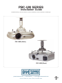
PBC-UM SERIES
PBC-UMW (White)
PBC-UMS (Black)
premiermounts.com | p. 800.368.9700 | e. [email protected]
500 W Central Ave, Suite A, Brea, CA 92821 USA

Warning Statements
Weight Limit
Maximum Weight: 60 lbs.
AVERTISSEMENT
THE CEILING STRUCTURE MUST BE CAPABLE OF SUPPORTING 60 LBS. IF NOT, THE CEILING MUST BE REINFORCED. PROPER INSTALLATION PROCEDURE IS A
QUALIFIED SERVICE TECHNICIAN, AS OUTLINED IN THE INSTALLATION INSTRUCTIONS, MUST BE ADHERED TO. FAILURE TO DO SO COULD RESULT IN SERIOUS
PERSONAL INJURY, OR EVEN DEATH.
SAFETY MEASURES MUST BE PRACTICED AT ALL TIMES DURING THE INSTALLATION OF THIS PRODUCT. USE PROPER SAFETY GEAR AND TOOLS FOR THE
INSTALLATION PROCEDURE TO PREVENT PERSONAL INJURY.
PRIOR TO THE INSTALLATION OF THIS PRODUCT, THE INSTALLATION INSTRUCTIONS SHOULD BE READ AND COMPLETELY UNDERSTOOD. THE INSTALLATION
INSTRUCTIONS MUST BE READ TO PREVENT PERSONAL INJURY AND PROPERTY DAMAGE. KEEP THESE INSTALLATION INSTRUCTIONS IN AN EASILY ACCESSIBLE
LOCATION FOR FUTURE REFERENCE.
Indicates that the power plug is to be disconnected from the power outlet
Safety Precautions must be taken at all times
Warning and Caution statements.
installation.
Do not install on a structure that is prone to vibration, movement or chance of impact. Failure to do so could result in damage to the projector and/or damage to the mounting surface.
.
hardware (which is commercially available).
LA STRUCTURE DE PLAFOND DOIT ÊTRE CAPABLE DE SOUTENIR 40 LIVRES. SINON, LE PLAFOND DOIT ÊTRE RENFORCÉ. LA PROCÉDURE D'INSTALLATION APPRO-
PRIÉE PAR UN TECHNICIEN DE SERVICE QUALIFIÉ, COMME INDIQUÉ DANS LES INSTRUCTIONS D'INSTALLATION, DOIT ÊTRE RESPECTÉE. LE NON-RESPECT DE CETTE
CONSIGNE PEUT ENTRAÎNER DES BLESSURES GRAVES OU MÊME LA MORT.
DES MESURES DE SÉCURITÉ DOIVENT ÊTRE PRATIQUÉES À TOUT MOMENT PENDANT L'INSTALLATION DE CE PRODUIT. UTILISER DES ÉQUIPEMENTS DE PROTECTION
ET DES OUTILS APPROPRIÉS POUR QUE LA PROCÉDURE D'INSTALLATION ÉVITE LES BLESSURES CORPORELS.
AVANT L'INSTALLATION DE CE PRODUIT, LES INSTRUCTIONS D'INSTALLATION DEVRAIENT ÊTRE LUES ET COMPRISES COMPLÈTEMENT. LES INSTRUCTIONS
D'INSTALLATION DOIVENT ÊTRE LUES POUR EMPÊCHER LE DOMMAGE CORPOREL ET LES DÉGATS MATÉRIELS. MAINTENIR CES INSTRUCTIONS D'INSTALLATION DANS
UN ENDROIT FACILEMENT ACCESSIBLE POUR RÉFÉRENCE ULTÉRIEURE.
Indique que la prise de courant doit être débranchée de la sortie de puissance.
Les mesures de sécurité doivent être prises à tout moment.
Messages d’avertissement et de mise en garde.
Une structure sécurisée doit soutenir le poids, ou la charge, du projecteur
avant l'installation.
Ne pas installer sur une structure qui est sujet aux vibrations, à la circulation ou la chance de l'impact. Tout manquement à ce règlement pourrait avoir comme conséquence des dom-
mages au projecteur et/ou des dommages à la surface de montage.
Éviter d’installer dans la proximité des appareils de chauffage, cheminées, rayonnement solaire direct, conditionnement d’air ou d’autres sources d’énergie thermique directe. Le défaut
de le faire pourrait endommager l’écran et pourrait augmenter le risque d’incendie.
.
Surfaces de montage recommandées : goujons en bois et béton plein-plat. Si le bâti doit être installé sur n'importe quelle surface autre que les goujons en bois, utiliser le matériel ap-
proprié (qui est disponible commercialement).
premiermounts.com | p. 800.368.9700 | e. [email protected]

1/8" Drill bit
#14 x 2" Wood
Screw
x 1
x 3
M2.5 x 10mm
x 4
M3 x 12mm
x 4
M4 x 12mm
x 4
M5 x 12mm M6 x 12mm
M6 x 25mm
x 4 x 4
x 1
5/8 Barrel Cap
M5 Security
Allen Key
Green Level
x 4
x 1
x 1
x 1
M3 Security
Allen Key
x 1
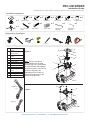
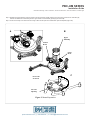
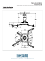
A
Single Wooden Stud
Mounts
B
Solid Structure
Mounting Points
C
Ceiling Plate
D
Security Allen Wrench
E
Extension
F
Tension Knobs
G
Safety Knob
H
Security Screws
I
Leveling Screws
J
Universal Mounting
bracket
K
Leg Assembly
L
Projector (not included)
M
Tri-Lock Opening
NOTE: The four (two-piece)
leg assemblies can be used as
single leg or any combination
together as shown in Options
1 and 2. The number of legs
may vary depending on the
projector.
D
D
M
H
J
L
L
J
A
B
K
G
E
C
M
I
H
F
Option 2
Option 1
Single Leg
Combination
Leg
Note: The four (two piece)
leg assemblies can be used
as single leg or any combination
of single and dual legs together
as show in Options 1 and 2. The
number of legs may vary
depending on the number of
mounting points found on the
bottom of the projector.
A
Single Wooden Stud
Mounts
B
Solid Structure
Mounting Points
C
M3 Security Allen
Wrench
D
Security Allen Wrench
E
1.5” nipple (NTP)
F
Tension Knobs
G
Safety Knob
H
Security Screws
I
Leveling Screws
J
Universal Mounting
bracket
K
Leg Assembly
L
Projector (not included)
M
Tri-Lock Opening
H
J
L
J
A
B
K
G
E
C
M
I
H
F
Option 2
Option 1
D
D
M
Single Leg
Combination
Leg
A
Single Wooden Stud
Mounts
B
Solid Structure
Mounting Points
C
M3 Security Allen
Wrench
D
Security Allen Wrench
E
1.5” nipple (NTP)
F
Tension Knobs
G
Safety Knob
H
Security Screws
I
Leveling Screws
J
Universal Mounting
bracket
K
Leg Assembly
L
Projector (not included)
M
Tri-Lock Opening
H
J
L
L
J
A
B
K
G
E
C
M
I
H
F
Option 2
Option 1
D
D
M
Single Leg
Combination
Leg
Installation Guide
Installationsanleitung, Guía de Instalacíon, Guida de Installazione, Guide d’Installation, Installatie gids
PBC-UM SERIES
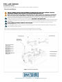
Included components
Required for installation
premiermounts.com | p. 800.368.9700 | e. [email protected]

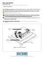
Projector Preparation
injury and possible damage to the projector.
THE PROJECTOR IS FRAGILE. HANDLE WITH CARE AT ALL TIMES.
reference information regarding installation dimensions such as distance from the screen to the lens of the projector, top of the lens placement to the top screen
etc.
avoir comme conséquence des dommages corporels sérieux et peut éventuellement endommager le projecteur.
LE PROJECTEUR EST FRAGILE. MANIPULER AVEC SOIN À TOUT MOMENT.
Passer en revue le manuel d'exploitation de la fabrication de projecteurs et se référer à la section de support de plafond dans le manuel de l'opérateur. Ici,
vous trouverez normalement des informations de référence importantes concernant des dimensions d'installation telles que la distance de l'écran à la lentille du
projecteur, la hauteur du positionnement de la lentille de l'écran du haut, etc. Le respect de ces recommandations au cours de votre installation vous permettront
Mounting
Points Inverted
Projector
Flat
Surface
Blanket /
Soft Cloth
Figure 1. Projector Preparation
Step 2. Identify the number of mounting points and screw thread size. Most projectors have either three or four mounting points and are M4, M5, or M6 in
thread size (Figure 1).
Installation Guide
Installationsanleitung, Guía de Instalacíon, Guida de Installazione, Guide d’Installation, Installatie gids
PBC-UM SERIES
premiermounts.com | p. 800.368.9700 | e. [email protected]

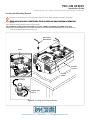
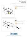
Step 3. Separate the upper assembly from the projector mounting bracket by slightly loosening the two tension knurl knobs to create free play
between the bracket tri-lock assembly and the upper section tri-lock assembly points (Figure 2A and 2B).
Step 4. Loosen the security screw knurl knob far enough to allow the two parts to be rotated 180º apart and separate (Figure 2C).
Figure 2. Mount Preparation
A
B
C
Tension
Knobs
Upper
Assembly
Safety
Knob
Tri -Lock
Opening
Rotate 180 °
To unlock
Installation Guide
Installationsanleitung, Guía de Instalacíon, Guida de Installazione, Guide d’Installation, Installatie gids
PBC-UM SERIES
premiermounts.com | p. 800.368.9700 | e. [email protected]

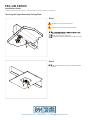
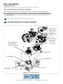
Figure 3. Bracket Installation
The two-piece mounting legs are designed to allow for the positioning of each leg around projector air vents located on the base of the projector. Where
applicable, each leg mount may be shortened by removing the locking screw
. Each leg should then be adjusted so that they can mount to the
Universal Mount (Figure 3).
Step 1. Locate the mounting points on the bottom of the projector and use the appropriate number of mounting legs.
Step 2. Select the mounting hardware that the projector requires and loosely install the universal mount on the projector.
Les pattes de support en deux pièces sont conçues pour tenir compte du positionnement de chaque patte autour des évents de projecteur localisés sur la base
du projecteur. Là où applicable, chaque bâti de patte peut se raccourcir en enlevant la vis de verrouillage. Cela permettra un meilleur ajustement de support,
dans l'ensemble.
Pour une installation plus facile, les pattes de support devraient être montés au projecteur. Chaque patte devrait alors être ajustée de sorte qu'elles puisse
monter au Montage universel (le schéma 3).
Bracket Installation
Installation Guide
Installationsanleitung, Guía de Instalacíon, Guida de Installazione, Guide d’Installation, Installatie gids
PBC-UM SERIES
premiermounts.com | p. 800.368.9700 | e. [email protected]

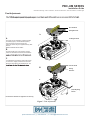
DOWN
UP
Figure 4. Leveling the Mounting Bracket
M5 Security
Allen Wrench
Level
Inverted
Projector
Leveling
Barrels
Adjusting the
Mount.
Secure but do not over tighten the mounting hardware. Failure to do so will result in damaging the threads in the projector.
projecteur.
Step 1. Rotate the leveling barrels to level the mounting bracket.
Step 3. When the desired position is achieved, tighten the mounting screws to the projector and then tighten the security hex head leg
screw with the M5 Security Allen Wrench (Figure 4).
Leveling the Mounting Bracket
Installation Guide
Installationsanleitung, Guía de Instalacíon, Guida de Installazione, Guide d’Installation, Installatie gids
PBC-UM SERIES
premiermounts.com | p. 800.368.9700 | e. [email protected]

Securing the Upper Assembly Ceiling Plate
Step 1
Step 2
desired installation location.
Identify the center of the ceiling stud.
Use a pencil to mark the location of the ceiling stud center.
Minimum of 2 X 4 wood stud to be used
Minimum de 2 X 4 bois goujon pour être utilisé
Use a pencil and mark 2 mounting hole locations through
the slots.
Installation Guide
Installationsanleitung, Guía de Instalacíon, Guida de Installazione, Guide d’Installation, Installatie gids
PBC-UM SERIES
premiermounts.com | p. 800.368.9700 | e. [email protected]

#14 x 2" Wood Screw
x 2
Tighten each screw until the ceiling plate is secure against
the ceiling.
Do not overtighten the mounting screws.
Éviter de trop serrer les vis de montage.
Step 4
Step 3
Drill a “pilot hole” in the center using a 1/8” drill bit and power drill.
Only use a 1/8” drill bit when drilling the pilot holes.
N’utiliser qu’un foret de 1/8” lors du forage de guidage.
Installation Guide
Installationsanleitung, Guía de Instalacíon, Guida de Installazione, Guide d’Installation, Installatie gids
PBC-UM SERIES
premiermounts.com | p. 800.368.9700 | e. [email protected]

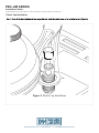
Figure 6. Low Profile Installation
2
1
Tension Knurl
Insert universal bracket
to the tri -lock, then
rotate the projector 180 °
The alignment slot
must be in direct
alignment with the
safety knob to lock
the mounting
bracket to the upper
assembly.
To secure the
mount, replace the
red safety knurl
knob with one (1)
M6 x 25 security
screw (supplied).
Projector
Tri -Lock Opening
Universal Mount
Alignment Slot
Securing the Projector to the Upper Assembly
Step 1. Make sure the three-knurl knobs are loosened to fully expose to the "tri-lock" mounting plate in the base of the upper assembly.
Step 2. Carefully lift the projector and insert the mounting bracket mating special tri-lock cutout into the mating portion of the upper assembly.
in the upper assembly
Step 4. Tighten the remaining two tension knurl knobs until the mount becomes rigid. The safety knob should line up with the alignment slot on
the mounting bracket
Follow the numbering sequence prior to securing the projector to the upper assembly.
Installation Guide
Installationsanleitung, Guía de Instalacíon, Guida de Installazione, Guide d’Installation, Installatie gids
PBC-UM SERIES
premiermounts.com | p. 800.368.9700 | e. [email protected]

tilt, roll and yaw to optimize the projected image.
Final Adjustments
A
The height can be adjusted by rotating the PBC
clockwise (higher) / counterclockwise (lower).
Once the height is achieved, tighten the
locking set screw using the supplied Security Allen
Wrench.
B
To adjust the tilt angle of the projector, slightly
loosen the side M8 screws and tilt to the desired
screws.
C
If roll adjustment is needed to square the images
on the screen, slightly loosen the front and rear
M8 screws and adjust to the desired angle. The
Re-check the hardware for tightness and security
Figure 7. Final Adjustments
A
Wooden Stud
Ceiling Structure
Locking Set Screw
C
B
Wooden Stud
Ceiling
Structure
(Roll) Adjusting
Screws
NOTE: A minimum of 4 full rotation.
Installation Guide
Installationsanleitung, Guía de Instalacíon, Guida de Installazione, Guide d’Installation, Installatie gids
PBC-UM SERIES
premiermounts.com | p. 800.368.9700 | e. [email protected]

Figure 8. Plastic Cap Installation
Plastic Cap Installation
Installation Guide
Installationsanleitung, Guía de Instalacíon, Guida de Installazione, Guide d’Installation, Installatie gids
PBC-UM SERIES
premiermounts.com | p. 800.368.9700 | e. [email protected]

All measurements are in inches (mm).
Figure 9. Technical Dimensions
1.5” (NPT) Nipple
Security
Installation Guide
Installationsanleitung, Guía de Instalacíon, Guida de Installazione, Guide d’Installation, Installatie gids
PBC-UM SERIES
premiermounts.com | p. 800.368.9700 | e. [email protected]

9530-002-021-0X Rev.11
Premier Mounts intends to make this manual accurate and complete. However, Premier Mounts makes no claim that the information
contained herein covers all details, conditions or variations, nor does it provide for every possible contingency in connection with
the installation or use of this product. The information contained in this document is subject to change without notice or obligation of
any kind. Premier Mounts makes no representation of warranty, expressed or implied, regarding the information contained herein.
PREMIER MOUNTS
LIMITED LIFETIME WARRANTY
What and Who is Covered by this Limited Lifetime Warranty
Premier Mounts warrants all mounting products to be free from defects in material and workmanship
for the lifetime of the original installation of the product.
What Premier Mounts Will Do
At the sole option of Premier Mounts, Premier Mounts will repair or replace any product or product
part that is defective. If Premier Mounts chooses to replace a defective product or part, a replacement
product or part will be shipped to you at no charge, but you must pay any related labor costs.
What is Not Covered: Limitations
Premier Mounts disclaims any liability for damage to mounts, adapters, displays, projectors, other
or misuse of its products.
NOTWITHSTANDING ANYTHING TO THE CONTRARY IN THIS WARRANTY, THIS WARRANTY
IS LIMITED TO FIVE YEARS FROM THE DATE OF PURCHASE IN THE EVENT THAT THE WAR-
RANTED PRODUCT IS COMMERCIALLY RENTED OUT.
and related electrical items, are backed by a 3-year warranty.
Premier Mounts disclaims all other warranties, express or implied, including warranties of merchant-
-
quential damages, including but not limited to, inability to use its products or labor costs for remov-
ing and replacing defective products or parts. Some states do not allow the exclusion or limitation of
incidental or consequential damages, so the above limitation or exclusion may not apply to you.
What Customers Must Do for Warranty Service
If you discover a problem that you think may be covered by the warranty, you must report it in writ-
ing to the address below within thirty (30) days. Proof of purchase (an original sales receipt) from the
original consumer purchaser must accompany all warranty claims. Warranty claims must also include
a description of the problem, the purchaser’s name, address, and telephone number. General inqui-
ries can be addressed to Premier Mounts Customer Service at 1-800-368-9700. Warranty claims will
not be accepted over the phone or by fax.
How State Law Applies
state to state.
PREMIER MOUNTS
500 W Central Ave, Suite A
Brea, CA 92821
USA & CANADA
Phone: 800-368-9700
Fax: 800-832-4888
©
PREMIER MOUNTS
ATTN: Warrenty Claims
500 W Central Ave, Suite A
Brea, CA 92821
-
 1
1
-
 2
2
-
 3
3
-
 4
4
-
 5
5
-
 6
6
-
 7
7
-
 8
8
-
 9
9
-
 10
10
-
 11
11
-
 12
12
-
 13
13
-
 14
14


Premier Mounts PBC-UMS Mode d'emploi
- Catégorie
- Supports de projecteur
- Taper
- Mode d'emploi
- Ce manuel convient également à
dans d''autres langues
- English: Premier Mounts PBC-UMS User guide
Documents connexes
-
Premier Mounts CTM-MS1 Mode d'emploi
-
-
-
-
-
Premier Mounts PSD-HDCA Mode d'emploi
-
-
-
-