GOODMAN CTXG12QVJUS Guide d'installation
- Catégorie
- Climatiseurs split-system
- Taper
- Guide d'installation
Ce manuel convient également à

INSTALLATION MANUAL
DAIKIN ROOM AIR CONDITIONER
R410A Split Series
English
FrançaisEspañol
MODELS
CTXG09QVJUW
CTXG12QVJUW
CTXG18QVJUW
CTXG09QVJUS
CTXG12QVJUS
CTXG18QVJUS
Installation manual
Manuel d’installation
Manual de instalación
00_CV_3P436087-1.fm Page 1 Tuesday, April 26, 2016 2:23 PM

English■
1
Safety Considerations
Read these Safety Considerations for Installation carefully
before installing an air conditioner or heat pump. After
completing the installation, make sure that the unit operates
properly during the startup operation.
Instruct the user on how to operate and maintain the unit.
Inform users that they should store this installation manual
with the operation manual for future reference.
Always use a licensed installer or contractor to install this product.
Improper installation can result in water or refrigerant leakage,
electric shock, fire, or explosion.
Meanings of DANGER, WARNING, CAUTION, and NOTE
Symbols:
DANGER ···············Indicates an imminently hazardous
situation which, if not avoided, will
result in death or serious injury.
WARNING ·············Indicates a potentially hazardous
situation which, if not avoided, could
result in death or serious injury.
CAUTION ··············Indicates a potentially hazardous
situation which, if not avoided, may
result in minor or moderate injury.
It may also be used to alert against
unsafe practices.
NOTE ·····················Indicates situations that may result in
equipment or property-damage acci-
dents only.
DANGER
• Refrigerant gas is heavier than air and replaces oxygen.
A massive leak can lead to oxygen depletion, especially in
basements, and an asphyxiation hazard could occur leading
to serious injury or death.
• Do not ground units to water pipes, gas pipes, telephone
wires, or lightning rods as incomplete grounding can cause
a severe shock hazard resulting in severe injury or death.
Additionally, grounding to gas pipes could cause a gas leak
and potential explosion causing severe injury or death.
• If refrigerant gas leaks during installation, ventilate the area
immediately. Refrigerant gas may produce toxic gas if it
comes into contact with fire. Exposure to this gas could
cause severe injury or death.
• After completing the installation work, check that the
refrigerant gas does not leak throughout the system.
• Do not install unit in an area where flammable materials are
present due to risk of explosions that can cause serious
injury or death.
• Safely dispose all packing and transportation materials in
accordance with federal/state/local laws or ordinances.
Packing materials such as nails and other metal or wood
parts, including plastic packing materials used for
transportation may cause injuries or death by suffocation.
WARNING
• Only qualified personnel must carry out the installation work.
Installation must be done in accordance with this installation
manual. Improper installation may result in water leakage,
electric shock, or fire.
• When installing the unit in a small room, take measures to
keep the refrigerant concentration from exceeding allowable
safety limits. Excessive refrigerant leaks, in the event of an
accident in a closed ambient space, can lead to oxygen
deficiency.
• Use only specified accessories and parts for installation
work. Failure to use specified parts may result in water
leakage, electric shock, fire, or the unit falling.
• Install the air conditioner or heat pump on a foundation
strong enough that it can withstand the weight of the unit.
A foundation of insufficient strength may result in the unit
falling and causing injuries.
• Take into account strong winds, typhoons, or earthquakes
when installing. Improper installation may result in the unit
falling and causing accidents.
Contents
Safety Considerations ..................................... 1
Accessories ...................................................... 3
Choosing an Installation Site .......................... 3
1. Indoor unit.................................................................... 3
2. Wireless remote controller ........................................... 3
Indoor Unit Installation Diagram ..................... 4
Indoor Unit Installation .................................... 5
1. Installing the mounting plate ........................................ 5
2. Drilling a wall hole and installing wall embedded pipe ... 5
3. Installing the indoor unit............................................... 5
4. Wiring........................................................................... 8
5. Drain piping.................................................................. 9
Refrigerant Piping Work .................................. 9
1. Flaring the pipe end ..................................................... 9
2. Refrigerant piping....................................................... 10
Installation Tips .............................................. 11
1. Removing and installing the upper front panel........... 11
2. Removing and installing the front grille...................... 11
3. How to set the different addresses ............................ 12
4.
When connecting a wireless LAN connecting adapter
..... 12
5. When connecting to an HA system............................ 13
Trial Operation and Testing .......................... 14
1. Trial operation and testing ......................................... 14
2. Test items .................................................................. 14
01_EN_3P436087-1.fm Page 1 Friday, June 10, 2016 4:10 PM

English■
2
• Make sure that a separate power supply circuit is provided
for this unit and that all electrical work is carried out by
qualified personnel according to local, state, and national
regulations. An insufficient power supply capacity or
improper electrical construction may lead to electric shock
or fire.
• Make sure that all wiring is secured, that specified wires are
used, and that no external forces act on the terminal
connections or wires. Improper connections or installation
may result in fire.
• When wiring, position the wires so that the electrical wiring
box cover can be securely fastened. Improper positioning of
the electrical wiring box cover may result in electric shock,
fire, or the terminals overheating.
• Before touching electrical parts, turn off the unit.
• It is recommended to install a ground fault circuit interrupter
if one is not already available. This helps prevent electric
shock or fire.
•
Securely fasten the outdoor unit terminal cover (panel). If the
terminal cover/panel is not installed properly, dust or water
may enter the outdoor unit causing fire or electric shock.
• When installing or relocating the system, keep the
refrigerant circuit free from substances other than the
specified refrigerant (R410A) such as air. Any presence of
air or other foreign substance in the refrigerant circuit can
cause an abnormal pressure rise or rupture, resulting in
injury.
• Do not change the setting of the protection devices. If the
pressure switch, thermal switch, or other protection device is
shorted and operated forcibly, or parts other than those
specified by Daikin are used, fire or explosion may occur.
CAUTION
• Do not touch the switch with wet fingers. Touching a switch
with wet fingers can cause electric shock.
• Do not allow children to play on or around the unit to prevent
injury.
• The heat exchanger fins are sharp enough to cut. To avoid
injury wear gloves or cover the fins while working around
them.
• Do not touch the refrigerant pipes during and immediately
after operation as the refrigerant pipes may be hot or cold,
depending on the condition of the refrigerant flowing through
the refrigerant piping, compressor, and other refrigerant
cycle parts. Your hands may suffer burns or frostbite if you
touch the refrigerant pipes. To avoid injury, give the pipes
time to return to normal temperature or, if you must touch
them, be sure to wear proper gloves.
• Install drain piping to proper drainage. Improper drain piping
may result in water leakage and property damage.
• Insulate piping to prevent condensation.
• Be careful when transporting the product.
• Do not turn off the power immediately after stopping
operation. Always wait for at least 5 minutes before turning
off the power. Otherwise, water leakage may occur.
• Do not use a charging cylinder. Using a charging cylinder
may cause the refrigerant to deteriorate.
• Refrigerant R410A in the system must be kept clean, dry,
and tight.
(a) Clean and Dry -- Foreign materials (including mineral oils
such as SUNISO oil or moisture) should be prevented
from getting into the system.
(b)
Tight -- R410A does not contain any chlorine, does not
destroy the ozone layer, and does not reduce the earth’s
protection again harmful ultraviolet radiation. R410A can
contribute to the greenhouse effect if it is released.
Therefore take proper measures to check for the tightness
of the refrigerant piping installation. Read the chapter
Refrigerant Piping Work and follow the procedures.
• Since R410A is a blend, the required additional refrigerant
must be charged in its liquid state. If the refrigerant is
charged in a state of gas, its composition can change and
the system will not work properly.
• The indoor unit is for R410A. See the catalog for indoor
models that can be connected. Normal operation is not
possible when connected to other units.
• Remote controller (wireless kit) transmitting distance can be
shorter than expected in rooms with electronic fluorescent
lamps (inverter or rapid start types). Install the indoor unit far
away from fluorescent lamps as much as possible.
• Indoor units are for indoor installation only. Outdoor units
can be installed either outdoors or indoors. This unit is for
indoor use.
• Do not install the air conditioner or heat pump in the
following locations:
(a) Where a mineral oil mist or oil spray or vapor is produced,
for example, in a kitchen.
Plastic parts may deteriorate and fall off or result in water
leakage.
(b) Where corrosive gas, such as sulfurous acid gas, is
produced.
Corroding copper pipes or soldered parts may result in
refrigerant leakage.
(c) Near machinery emitting electromagnetic waves.
Electromagnetic waves may disturb the operation of the
control system and cause the unit to malfunction.
(d) Where flammable gas may leak, where there is carbon
fiber, or ignitable dust suspension in the air, or where
volatile flammables such as thinner or gasoline are
handled. Operating the unit in such conditions can cause
a fire.
• Take adequate measures to prevent the outdoor unit from
being used as a shelter by small animals. Small animals
making contact with electrical parts can cause malfunctions,
smoke, or fire. Instruct the user to keep the area around the
unit clean.
NOTE
•
The indoor unit should be positioned where the unit and inter-
unit wires (outdoor to indoor) are at least 3.3ft (1m) away from
any televisions or radios. (The unit may cause interference with
the picture or sound.) Depending on the radio waves, a distance
of 3.3ft (1m) may not be sufficient to eliminate the noise.
• Dismantling the unit, treatment of the refrigerant, oil and
additional parts must be done in accordance with the
relevant local, state, and national regulations.
• Do not use the following tools that are used with
conventional refrigerants: gauge manifold, charge hose, gas
leak detector, reverse flow check valve, refrigerant charge
base, vacuum gauge, or refrigerant recovery equipment.
• If the conventional refrigerant and refrigerator oil are mixed
in R410A, the refrigerant may deteriorate.
• This air conditioner or heat pump is an appliance that should
not be accessible to the general public.
• As design pressure is 604 psi, the wall thickness of field-
installed pipes should be selected in accordance with the
relevant local, state, and national regulations.
FTN001-U
01_EN_3P436087-1.fm Page 2 Friday, June 10, 2016 4:10 PM

English■
3
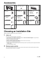
Accessories
Choosing an Installation Site
Before choosing the installation site, obtain user approval.
1. Indoor unit
The indoor unit should be positioned in a place where:
1) the restrictions on the installation requirements specified in “Indoor Unit Installation Diagram” on page 4 are met,
2) both the air inlet and air outlet are unobstructed,
3) the unit is not exposed to direct sunlight,
4) the unit is away from sources of heat or steam,
5) there is no source of machine oil vapor (this may shorten the indoor unit service life),
6) cool/warm air is circulated throughout the room,
7) the unit is away from electronic ignition type fluorescent lamps (inverter or rapid start type) as they may affect the remote
controller range,
8) no laundry equipment is nearby.
2. Wireless remote controller
Turn on all the fluorescent lamps in the room, if any, and find a location where the remote controller signals are properly
received by the indoor unit (within 19-11/16ft (6m)).
Mounting plate
1
Mounting plate fixing screw
M4 × 1” (M4 × 25mm)
5
Titanium apatite photocatalytic
air-purifying filter
2
Wireless remote
controller
1
Remote
controller holder
1
Remote
controller holder
fixing screw
M3 × 13/16”
(M3 × 20mm)
2
Dry battery
AAA. LR03
(alkaline)
2
Indoor unit
fixing screw
M4 × 1/2”
(M4 × 12mm)
2
Screw cover
2
Insulation tape
1
Operation
manual
1
Installation
manual
1
Warranty
1
A
B
C
D
E
F
G
H
J
K
L
M
N
01_EN_3P436087-1.fm Page 3 Friday, June 10, 2016 4:10 PM

English■
4
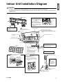
Indoor Unit Installation Diagram
CAUTION
• Do not hit or violently push the INTELLIGENT EYE sensor. This can lead to damage and malfunction.
• Do not place large objects near the INTELLIGENT EYE sensor. Also keep heating units or humidifiers outside the sensor’s
detection area.
Wrap the insulation pipe with the
finishing tape from bottom to top.
Front grille
Hook
Bottom frame
Before screwing the
remote controller
holder to the wall,
make sure that
control signals are
properly received
by indoor unit.
Service lid
The service lid is removable.
Opening method
1) Remove the service lid screws.
2) Pull out the service lid diagonally
down in the direction of the arrow.
3) Pull down.
Cut thermal insulation pipe to an
appropriate length and wrap it with tape,
making sure that no gap is left in the
insulation pipe’s cut line.
1-3/16” (30mm) or more
from ceiling
Upper front panel
1-15/16” (50mm) or more
from walls (on both sides)
Filter frame
Tab
Claw
Titanium apatite
photocatalytic
air-purifying filter
Air filter
Air filters
Screws M4 × 5/8” (M4 × 16mm)
C
air-purifying filter (2)
D Wireless remote controller
E Remote controller
holder
When dismounting the front grille, refer
to “2. Removing and installing the front grille”
on page 11.
A Mounting
plate
INTELLIGENT EYE sensor
Screw covers
J
The mounting plate should
be installed on a wall which
can support the weight of the
indoor unit.
A Mounting plate
How to attach the indoor unit
Hook the hooks of the bottom
frame to the mounting plate.
If the hooks are difficult to hook,
remove the front grille.
A
How to remove the indoor unit
Push up the lower part of the
front grille to release the hooks.
If it is difficult to release, remove
the front grille.
Mounting plate fixing
screws M4 × 1” (M4 × 25mm)
B
F Remote controller holder
fixing screws
M3 × 13/16” (M3 × 20mm)
Titanium apatite photocatalytic
A
E
Lower front panel
19-11/16” (500mm)
or more
Make sure that there are no
obstacles within 19-11/16 inch
(500mm) under the signal
receiver.
Such obstacles, if any, may have
an adverse influence on the
reception performance of the
receiver and the reception
distance may be shortened.
01_EN_3P436087-1.fm Page 4 Friday, June 10, 2016 4:10 PM

English■
5
Indoor Unit Installation
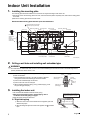
1. Installing the mounting plate
The mounting plate should be installed on a wall which can support the weight of the indoor unit.
1)Temporarily secure the mounting plate to the wall, make sure that the plate is completely level, and mark the drilling points
on the wall.
2)Secure the mounting plate to the wall with screws.
Recommended mounting plate retention spots and dimensions
2. Drilling a wall hole and installing wall embedded pipe
WARNING
For metal frame or metal board walls, be sure to use a wall embedded pipe and wall hole cover in the feed-through hole to
prevent possible heat, electric shock, or fire.
• Be sure to caulk the gaps around the pipes with caulking material to
prevent condensation.
1) Drill a feed-through hole with a 2-9/16 inch (65mm) diameter
through the wall at a downward angle toward the outside.
2) Insert a wall embedded pipe into the hole.
3) Insert a wall hole cover into wall pipe.
4) After completing refrigerant piping, wiring, and drain piping, caulk
the pipe hole gap with putty.
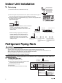
3. Installing the indoor unit
• The recommended installation method is back piping.
• When performing bottom piping or left side piping, refer to
“3-4. Bottom or left side piping” on page 7.
• Right side piping cannot be performed.
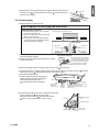
3-1. Right-back piping
1) Attach the drain hose to the underside of the refrigerant pipes with
adhesive vinyl tape.
2) Wrap the refrigerant pipes and drain hose together with insulation
tape.
Recommended mounting plate
retention spots (5 spots in all)
(Bolt size: 3/8 (M10))
(Bolt size: 3/8 (M10))
Gas pipe endLiquid pipe end
Place a leveler
on these tabs.
Through-the-wall hole
φ2-9/16 (65)
unit: inch (mm)
Drain hose
position
Place the pipe port
cover in this pocket.
39-5/16 (998)
14-1/16 (357)
5-5/16 (135)5-9/16 (142)
13-11/16 (348)
6-5/16 (160) 5-15/16 (151)
1-15/16
(49)
3-15/16
(100)
7-7/8 (200)
4-7/8 (124)
11-15/16 (303)
1-15/16
(49)
1-15/16
(50)
8 (203) 9-3/16 (234)
2-5/8
(67)
Use a tape
measure as
shown.
Position the end
of the tape
measure at .
Inside Outside
Caulking
(field supply)
Wall embedded pipe
(field supply)
Wall hole cover
(field supply)
φ2-9/16”
(65mm)
Left back pipingRight back piping
Bind refrigerant pipe and drain hose
together with adhesive vinyl tape.
K
01_EN_3P436087-1.fm Page 5 Friday, June 10, 2016 4:10 PM

English■
6
3) Pass the drain hose and refrigerant pipes through the wall hole, then position the
indoor unit on the mounting plate hooks, using the markings at the top of
the indoor unit as a guide.
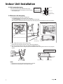
3-2. Left-back piping
1) Replace the drain plug and drain hose.
2) Attach the drain hose to the underside of the refrigerant
pipes with adhesive vinyl tape.
3) Be sure to connect the drain plug to the drain port in place
of without drain hose.
4) Shape the refrigerant pipes along the pipe path marking on the mounting plate.
5) Pass the drain hose and refrigerant pipes through the wall hole, then position the indoor unit on the mounting
plate hooks, using the markings at the top of the indoor unit as a guide.
6) Connect the refrigerant pipes.
7) In case of pulling the drain hose through the
back of the indoor unit, wrap the refrigerant
pipes and drain hose together with
insulation tape as shown in the figure.
8) Press the bottom edge of the indoor unit with both hands until it
is firmly caught by the mounting plate hooks.
Secure the indoor unit to the mounting plate with the
indoor unit fixing screws M4 × 1/2” (M4 × 12mm).
A Mounting plate
A
Replacing onto the left side
1) Remove the fixing screw on the right side
and remove the drain hose.
2) Remove the drain plug on the left side and
attach it to the right side.
3) Insert the drain hose and tighten with the
included fixing screw. Forgetting to tighten
this may cause water leakages.
How to replace the drain plug and drain hose
Drain hose attachment position
The drain hose is on the back of the unit.
Front side of unit
Attachment on the right side
(factory default)
Attachment on the left side
Drain hose Drain hose
Fixing screw Fixing screw
Right sideLeft side
How to set the drain plug
No gap
Insert a hexagonal wrench (3/16 inch (4mm)).
Do not apply lubricating oil (refrigerant
oil) to the drain plug when inserting it.
The application of lubrication oil to the
drain plug will deteriorate the plug to
cause drain leakage from the plug.
A
A
Drain hose
Bind with
adhesive
vinyl tape.
A Mounting plate
Caulk this hole
with putty or
caulking material.
Wrap insulation tape around the bent
portion of the refrigerant pipe.
Overlap at least half the width of the tape
with each turn.
K
K
Refrigerant pipes
Drain hose
Bottom frame
A Mounting plate
Indoor unit fixing screw
M4 × 1/2” (M4 × 12mm)
(2 points)
H
A
A
H
01_EN_3P436087-1.fm Page 6 Friday, June 10, 2016 4:10 PM

English■
7
Indoor Unit Installation
3-3. Wall embedded piping
Follow the instructions given under left-back piping.
1) Insert the drain hose to this depth so it won’t be pulled
out of the drain pipe.
3-4. Bottom or left side piping
1) Cut off the pipe port cover with a copping saw.
• For bottom piping: On the bottom of the front grille
• For left side piping: On the side cover (front grille side and unit side)
Apply the blade of the copping saw to the notch, and cut off the pipe port cover along the uneven inner surface.
2) After cutting off the pipe port cover, perform filing.
Remove the burrs along the cut section using a half round needle file.
3) Wrap the refrigerant pipes and drain hose together with insulation tape.
Then, insert the drain hose and refrigerant pipes into the wall hole after inserting them into the cut out piping hole
opened.
NOTE
• Be careful not to let chips enter the driving section of the arm.
• Be careful not to put pressure on the lower front panel.
Inner wall
Vinyl chloride
drain pipe (VP-30)
Drain hose
φ1-3/16” (30mm) or more
1-15/16”
(50mm)
or more
Insert the drain
hose to this depth
so it won’t be pulled
out of the drain pipe.
Outer wall
The figure shows the case of left-bottom piping.
Front grille side
Side cover
(front grille side)
Side cover (unit side)
K
Left side
piping
Right bottom piping Left bottom piping
Bind refrigerant pipe and drain hose
together with adhesive vinyl tape.
01_EN_3P436087-1.fm Page 7 Friday, June 10, 2016 4:10 PM

English■
8
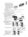
4. Wiring
Refer to the installation manual for the outdoor unit also.
WARNING
• Do not use tapped wires, extension cords, or starburst connections, as they may cause overheating, electric shock, or fire.
• Do not use locally purchased electrical parts inside the product. (Do not branch the power for the drain pump, etc., from the
terminal block.) Doing so may cause electric shock or fire.
• Do not connect the power wire to the indoor unit. Doing so may cause electric shock or fire.
CAUTION
When connecting the connection wire to the terminal block using a single core wire,
be sure to perform curling.
Problems with the installation may cause heat and fires.
, install as described in the installation manual supplied with the multi outdoor
unit.
1)
Remove the upper front panel, then remove the service lid.
(Refer to the opening method on page 4.)
2) Lift up the unit and place it on the mounting plate
hooks.
3) Remove the front grille.
(Refer to the removal method on page 11.)
4) Remove the conduit mounting plate and then secure the
conduit to the conduit mounting plate with the lock nut,
as shown in the illustration.
5) Strip wire ends (3/4 inch (20mm)).
6) Match wire colors with terminal numbers on the indoor
and outdoor unit’s terminal blocks and firmly secure the
wires in the corresponding terminals with the screws.
7) Connect the ground wire to the corresponding terminals.
8) Pull the wires lightly to make sure they are securely
connected.
9) In case of connecting to an adapter system, run the
remote controller cable and attach the S21.
(Refer to “5. When connecting to an HA system” on page 13.)
10) Attach the conduit mounting plate.
11) Shape the wires so that the service lid fits securely.
12) Attach the front grille.
13) Attach the service lid and the upper front panel.
Good Wrong
With a multi indoor unit
A Mounting plate
Hang indoor unit on the hooks
of mounting plate.
A
Screw
Lock nut
Conduit pipe
Conduit
Conduit
mounting plate
Electrical wiring box
Terminal block
Electrical wiring box
Use the specified wire type.
12 3
Shape wires so that the
service lid will fit securely.
1
2
3
123
L1 L
2
Wire size and length must
comply with local codes.
Firmly fix the wires with
the terminal screws.
Outdoor
unit
Indoor
unit
Firmly fix the wires with
the terminal screws.
01_EN_3P436087-1.fm Page 8 Friday, June 10, 2016 4:10 PM

English■
9
Indoor Unit Installation
5. Drain piping
1) Connect the drain hose, as described on the right.
2)
Remove the upper front panel and the air filters. (Refer to removal method on page 11.)
Pour some water into the drain pan to check the water flows smoothly.
3) If drain hose extension or embedded drain piping is required, use appropriate parts
that match the hose front end.
Figure of hose front end
• When drain hose requires extension, obtain an extension
hose with an inner diameter of 5/8 inch (16mm).
Be sure to thermally insulate the indoor section of the
extension hose.
• When connecting a rigid polyvinyl chloride pipe
(nominal diameter 1/2 inch (13mm)) directly to
the drain hose attached to the indoor unit as with
embedded piping work, use any commercially
available drain socket (nominal diameter 1/2 inch
(13mm)) as a joint.
Refrigerant Piping Work
WARNING
• Do not apply mineral oil on flared part.
• Prevent mineral oil from getting into the system as this would reduce the service life of the units.
• Never use piping which has been used for previous installations. Only use parts which are delivered with the unit.
• Never install a dryer to this R410A unit in order to guarantee its service life.
• The drying material may dissolve and damage the system.
• Incomplete flaring may result in refrigerant gas leakage.
, install as described in the installation manual supplied with the multi outdoor unit.
1. Flaring the pipe end
1) Cut the pipe end with a pipe cutter.
2) Remove burrs with the cut surface facing downward
so that the filings do not enter the pipe.
3) Put the flare nut on the pipe.
4) Flare the pipe.
5) Check that the flaring has been done correctly.
The drain hose should
be inclined downward.
No trap is permitted.
Do not put the end
of the hose in water.
ϕ11/16”
(ϕ18mm)
ϕ5/8”
(ϕ16mm)
Indoor unit
drain hose
Extension drain hose
Heat insulation tube (field supply)
ϕ5/8”
(ϕ16mm)
Drain hose supplied
with the indoor unit
Commercially available
drain socket
(nominal diameter 1/2 inch
(13mm))
Commercially available
rigid polyvinyl chloride pipe
(nominal diameter 1/2 inch
(13mm))
Drain hose supplied with
the indoor unit
ϕ11/16”
(ϕ18mm)
With a multi indoor unit
A
A
Cut exactly at
right angles.
Remove burrs.
Flaring
Set exactly at the position shown below.
Die
0-0.020 inch
(0-0.5mm)
Clutch-type
Flare tool for
R410A
0.039-0.059 inch
(1.0-1.5mm)
Clutch-type
(Rigid-type)
0.059-0.079 inch
(1.5-2.0mm)
Wing-nut type
(Imperial-type)
Conventional flare tool
The flare's inner
surface must be
flaw-free.
The pipe end must
be evenly flared in a
perfect circle.
Make sure that the
flare nut is fitted.
Check
01_EN_3P436087-1.fm Page 9 Friday, June 10, 2016 4:10 PM

English■
10
2. Refrigerant piping
CAUTION
• Use the flare nut fixed to the main unit. (This is to prevent the flare nut from cracking as a result of deterioration over time.)
• To prevent gas leakage, apply refrigeration oil only to the inner surface of the flare. (Use refrigeration oil for R410A.)
• Use a torque wrench when tightening the flare nuts to prevent damage to the flare nuts and gas leakage.
• Align the centers of both flares and tighten the flare nuts 3 or 4 turns by hand, then tighten them fully with a spanner and a
torque wrench.
2-1. Caution on piping handling
• Protect the open end of the pipe against dust and moisture.
• All pipe bends should be as gentle as possible. Use a pipe bender for
bending.
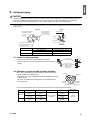
2-2. Selection of copper and heat insulation materials
When using commercial copper pipes and fittings, observe the following:
• Insulation material: Polyethylene foam
Heat transfer rate: 0.041 to 0.052W/mK (0.024 to 0.030Btu/fth°F (0.035 to
0.045kcal/mh°C))
Be sure to use insulation that is designed for use with HVAC Systems.
• ACR Copper only.
• Be sure to insulate both the gas and liquid piping and observe the insulation dimensions as below.
• Use separate thermal insulation pipes for gas and liquid refrigerant pipes.
Piping size Flare nut tightening torque
Gas side
O.D. 3/8 inch (9.5mm) 24-1/8–29-1/2ft • Ibf (32.7-39.9N • m)
O.D. 1/2 inch (12.7mm) 36-1/2–44-1/2ft • lbf (49.5-60.3N • m)
Liquid side O.D. 1/4 inch (6.4mm) 10-1/2–12-3/4ft • lbf (14.2-17.2N • m)
Piping size Minimum bend radius Piping thickness Thermal insulation size
Thermal insulation
thickness
Gas side
O.D. 3/8 inch
(9.5mm)
1-3/16 inch (30mm)
or more
0.031 inch (0.8mm)
(C1220T-O)
I.D. 15/32-19/32 inch
(12-15mm)
13/32 inch
(10mm) Min.
O.D. 1/2 inch
(12.7mm)
1-9/16 inch (40mm)
or more
I.D. 9/16-5/8 inch
(14-16mm)
Liquid side
O.D. 1/4 inch
(6.4mm)
1-3/16 inch (30mm)
or more
I.D. 5/16-13/32 inch
(8-10mm)
Do not apply refrigeration
oil to the outer surface.
Flare nut
Apply refrigeration
oil only to the inner
surface of the flare.
Do not apply refrigeration oil to
the flare nut to avoid tightening
with excessive torque.
Apply oil
Torque wrench
Piping union
Flare nut
Spanner
Tighten
Wall
If no flare cap is
available, cover the
flare mouth with
tape to keep dirt
and water out.
Rain
Be sure to
place a cap.
Gas pipe
Liquid pipe
Gas pipe
insulation
Liquid pipe
insulation
Finishing tape Drain hose
01_EN_3P436087-1.fm Page 10 Friday, June 10, 2016 4:10 PM

English■
11
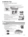
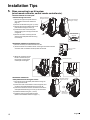
Installation Tips
1. Removing and installing the upper front panel
2. Removing and installing the front grille
CAUTION
Be sure to wear protection gloves.
• Removal method
1) Remove the upper front panel and air filters.
2) Remove the service lid. (Refer to the opening method on page 4.)
3) Disconnect the wire harnesses from the wire clamp, and remove the wire
harnesses from the connectors.
4) Push the lower front panel up until it stops.
5) Dismount the flap (large).
6) Open the 2 screw covers, and remove 4 screws from the front grille.
(The screw covers are not factory-mounted.)
Back of the upper front panel
Front panel shaft
3-1) SlideShaft hole
3-2) Pull
Back of the upper front panel
2) Slide
The upper front panel does not
open any more than as shown in
the figure. Do not force it open
any further than that.
Front panel lock
Removal method
1) Open the upper front panel.
2) Slide the front panel locks on the back of the front panel upward to release the locks (left and right sides).
3) Remove the panel shafts on both sides from the shaft holes, and dismount the upper front panel.
•
Installation method
1) Slide the front panel locks on the back of the front panel upward to release the
locks (left and right sides).
2) Insert the panel shafts on both sides of the upper front panel into the shaft holes.
3) Slide the front panel locks on each side downward to lock them.
4) Close the upper front panel slowly. (See Fig. 1)
5) Do not push on the panel to close it. (See Fig. 2)
6) Turn on the unit using the remote controller. Wait till the upper and lower front
panels are completely open. Then, turn off the unit using the remote controller
again. (See Fig. 3)
7) Once the both panels close completely, gently push the upper front panel to
hook it into position. (See Fig. 4)
•
Fig. 1
Fig. 2
Fig. 3
Fig. 4
ON/OFF
“click”
“click”“click”
“click”“click”
Wire clamp
Connectors
Wire harnesses
Flap (large)
Remove by pushing to the right while bending it slightly
4 screws
• Opening method
Use a long flat plate such as a
ruler and wrap it in a cloth so
as not to damage the product.
Downward
Screw covers
J
01_EN_3P436087-1.fm Page 11 Friday, June 10, 2016 4:10 PM

English■
12
7) Wear protection gloves and insert both hands
under the front grille as shown in the figure.
8) Remove the front grille from the 3 upper hooks
by pushing up the top side of the front grille, pull
the front grille toward you by holding both ends
of the front grille, and dismount the front grille.
•
If the grille is hard to remove, insert a long flat plate*
through the gap in the side cover as shown in the
figure, and turn the plate inwards to disengage the
hooks (3 hooks each on the right and left sides) so
that you can remove the grille easily.
* Such as a ruler wrapped in a cloth
• Installation method
1) Install the front grille and firmly engage the upper hooks (3 locations), right and left sides hooks (each 3 locations).
2) Install 4 screws of the front grille, and close the 2 screw covers.
3) Mount the flap (large).
4) Lower the lower front panel to the original position.
5) Attach the wire harnesses to the 2 connectors and secure the wire harnesses with the wire clamp.
6) Install the air filters and then mount the upper front panel.
3. How to set the different addresses
When 2 indoor units are installed in one room,
the 2 wireless remote controllers can be set for
different addresses. Change the address
setting of one of the two units. When cutting
the jumper be careful not to damage any of the
surrounding parts.
1) Remove the upper front panel and front
grille. (Refer to the removal method on page
11.)
2) Cut the address jumper (JA) on the printed
circuit board.
3) Cut the address jumper (J4) in the remote
controller.
• Be careful not to cut jumper (J8).
4. When connecting a wireless LAN connecting adapter
• Connection method
1) Remove the upper front panel.
(Refer to the removal method on page 11.)
2) Open the cover, grab the connecting cord
with your fingers and pull it out.
3) Remove the binding band and pull the
insulation tube off the connecting cord.
4) Connect the wireless LAN connecting
adapter.
(For details on connection procedures,
refer to the installation manual for the
wireless LAN connecting adapter.)
5) Place the adapter case into the indoor
unit and close the cover.
6) Install the upper front panel.
(Refer to the installation method on page 11.)
Upper hooks
8-2) Pull toward you.
8-1) Push up.
Side hooks
1
2
JA
Indoor unit
Bottom of electrical wiring box
INTELLIGENT EYE sensor
Remote controller
Jumper
(J8) (J4)
ADDRESS
EXIST
CUT
ADDRESS : JA
EXIST : 1
CUT : 2
Binding band
Connector
(white)
2-2) Grab the
connecting
cord
2-3) Pull out the
connecting
cord
2-1) Open
the
cover
Insulation tube
3-2) Pull off the
insulation tube
3-1) Cut and remove
the binding band
Close
Close the cover before
operating the unit.
CAUTION
Adapter
case
Cover
01_EN_3P436087-1.fm Page 12 Friday, June 10, 2016 4:10 PM

English■
13
Installation Tips
5. When connecting to an HA system
(wired remote controller, central remote controller etc.)
• Removal methods for metal plate
electrical wiring box covers
1) Remove the upper front panel and front
grille. (Refer to the removal method on
page 11.)
2) Remove the electrical wiring box. (1 screw)
3) Remove the 4 tabs and dismount the metal
plate electrical wiring box cover (A).
4) Pull down the hook on the metal plate
electrical wiring box cover (B), and remove
a single tab.
5) Remove the 2 tabs on the top part and
dismount the metal plate electrical wiring
box cover (B).
• Attachment methods of connection cord
1) Remove the factory-mounted connector from S21.
2) Tie the harnesses in a bundle as shown in the figure so that the removed
connector does not interfere with the printed circuit board.
3) Attach the connection cord to
the S21 connector and pull
the harness out through the
notched part in the figure.
• Attachment methods for
metal plate electrical wiring box covers
1) Hook the top part of the metal plate electrical wiring box
cover (B) on the 2 tabs.
2) Press in the hook on the bottom to catch a single tab, and
mount the metal plate electrical wiring box cover (B).
3)
Insert the connector into the hole, and hook and mount the
metal plate electrical wiring box cover (A) onto the 4 tabs.
4)
Install the electrical wiring box. (1 screw)
5)
Install the upper front panel and front grille.
(Refer to the installation method on page 11.)
Metal plate electrical
wiring box cover (B)
Metal plate electrical
wiring box cover (A)
Screw
From back side
Single tab
Pull down
Factory-mounted
connector
Screw
HA connector (S21)
Metal plate
electrical wiring
box cover (A)
Metal plate electrical
wiring box cover (B)
01_EN_3P436087-1.fm Page 13 Friday, June 10, 2016 4:10 PM

English■
14
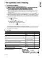
Trial Operation and Testing
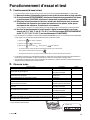
1. Trial operation and testing
• Trial operation should be carried out in either COOL or HEAT operation.
1-1. Measure the supply voltage and make sure that it is within the specified range.
1-2. In COOL operation, select the lowest programmable temperature;
in HEAT operation, select the highest programmable temperature.
1-3. Carry out the trial operation following the instructions in the operation manual to
ensure that all functions and parts, such as the movement of the louvers, are
working properly.
• To protect the air conditioner, restart operation is disabled for 3 minutes after the system has been turned off.
1-4. After trial operation is complete, set the temperature to a normal level (78°F to 82°F
(26°C to 28°C) in COOL operation, 68°F to 75°F (20°C to 24°C) in HEAT operation).
• When operating the air conditioner in COOL operation in winter, or HEAT operation in summer, set it to the trial operation
mode using the following method.
• The air conditioner draws a small amount of power in its standby mode. If the system is not to be used for some time after
installation, shut off the circuit breaker to eliminate unnecessary power consumption.
• If the circuit breaker trips to shut off the power to the air conditioner, the system will restore the original operation mode
when the circuit breaker is opened again.
2. Test items
* Check that the jumper (J8) has not been cut. If it has
been cut, contact the service shop.
Test items Symptom Check
Indoor and outdoor units are installed securely. Fall, vibration, noise
No refrigerant gas leaks.
Incomplete cooling/heating
function
Refrigerant gas and liquid pipes and indoor drain hose extension are
thermally insulated.
Water leakage
Draining line is properly installed. Water leakage
System is properly grounded. Electrical leakage
Only specified wires are used for all wiring, and all wires are connected
correctly.
No operation or burn damage
Indoor or outdoor unit’s air inlet or air outlet are unobstructed.
Incomplete cooling/heating
function
Stop valves are opened.
Incomplete cooling/heating
function
Indoor unit properly receives remote controller commands. No operation
will be displayed when the MODE button is pressed.*
No heating
Pipes and wires are connected to the corresponding terminal blocks/
connection ports for the connected unit.
No cooling/heating
1) Press to turn on the system.
2) Press both of and at the same time.
3) Press , select “ ”, and press for confirmation.
• Trial operation will stop automatically after about 30 minutes.
To stop the operation, press .
• Some of the functions cannot be used in the trial operation mode.
Jumper (J8)
01_EN_3P436087-1.fm Page 14 Friday, June 10, 2016 4:10 PM

Français■
1
Considérations sur la sécurité
Lisez soigneusement ces
Considérations sur la sécurité
pour
l’installation avant d’installer un climatiseur ou une pompe à
chaleur. Après avoir complété l’installation, assurez-vous que
l’unité fonctionne correctement pendant l’opération de démarrage.
Former l’utilisateur sur la façon d’exploiter et d’entretenir l’unité.
Informer les utilisateurs qu’ils doivent conserver ce manuel
d’installation avec le manuel d’utilisation pour référence ultérieure.
Utilisez toujours un installateur ou un entrepreneur agréé pour installer ce produit.
Une mauvaise installation peut provoquer une fuite d’eau ou de
réfrigérant, une électrocution, un incendie ou une explosion.
Signification des symboles
DANGER
,
AVERTISSEMENT
,
ATTENTION
, et
AVIS
:
DANGER
················ Indique une situation extrêmement dange-
reuse qui, si elle n’est pas évitée, entraî-
nera la mort ou des blessures graves.
AVERTISSEMENT
Indique une situation potentiellement
dangereuse qui, si elle n’est pas évitée, peut
entraîner la mort ou des blessures graves.
ATTENTION
·············Indique une situation potentiellement
dangereuse qui, si elle n’est pas évitée, peut
entraîner des blessures mineures à modérées.
Il peut également être utilisé pour alerter
contre des pratiques dangereuses.
AVIS
·························· Indique des situations pouvant provoquer des
accidents et l’endommagement de l’équipe-
ment ou des dégâts matériels seulement.
DANGER
•
Le gaz réfrigérant est plus lourd que l’air et remplace l’oxygène.
Une fuite importante peut conduire à un appauvrissement en
oxygène, en particulier en sous-sol, et un risque d’asphyxie
peut survenir et entraîner des blessures graves ou la mort.
•
Ne reliez pas les unités à des conduites d’eau, à des tuyaux de gaz,
à des câbles téléphoniques ou à des paratonnerres, car une mise à
la terre incomplète pourrait provoquer un risque d’électrocution
important pouvant entraîner des blessures graves ou la mort. De
plus, relier des tuyaux de gaz peut provoquer une fuite de gaz, une
explosion potentielle entraînant des blessures graves ou la mort.
•
Si vous constatez des fuites de gaz réfrigérant pendant l’installation,
aérez immédiatement la zone. Le gaz réfrigérant peut produire un
gaz toxique s’il entre en contact avec une flamme. L’exposition à ce
gaz peut provoquer des blessures graves ou la mort.
• Après l’achèvement des travaux d’installation, vérifiez que le
gaz réfrigérant ne fuit pas à travers le système.
• N’installez pas une unité dans un endroit où des matériaux
inflammables sont présents en raison du risque d’explosion
pouvant entraîner des blessures graves ou la mort.
•
Disposez de façon sécuritaire tous les matériaux d’emballage et
de transport conformément aux lois et réglementations
fédérales, étatiques et locales. Les matériaux d’emballage tels
que des clous et autres pièces métalliques ou en bois, y compris
les matériaux d’emballage en plastique utilisés pour le transport
peuvent causer des blessures ou la mort par suffocation.
AVERTISSEMENT
• Seul le personnel qualifié doit effectuer les travaux
d’installation. L’installation doit être effectuée conformément
à ce manuel d’installation. Une mauvaise installation peut
entraîner une fuite d’eau, une électrocution, ou un incendie.
•
Lors de l’installation de cette unité dans une petite pièce, prenez
des mesures pour maintenir la concentration de réfrigérant en
dessous des limites de sécurité admises. Les fuites excessives
de réfrigérant, dans le cas d’un accident dans un espace
ambiant clos, peuvent conduire à une carence en oxygène.
•
Utilisez seulement les accessoires et les pièces spécifiés pour les
travaux d’installation. Ne pas utiliser les pièces spécifiées peut entraîner
des fuites d’eau, une électrocution, un incendie ou la chute de l’unité.
•
Installez le climatiseur ou la pompe à chaleur sur une fondation
suffisamment solide pour qu’elle puisse supporter le poids de l’unité.
Une fondation de résistance insuffisante peut entraîner la chute de
l’unité et causer des blessures.
•
Lors de l’installation, prenez en compte les vents forts, les
typhons, ou les tremblements de terre. Une mauvaise installation
peut provoquer la chute de l’unité et causer des accidents.
Sommaire
Considérations sur la sécurité ........................ 1
Accessoires ...................................................... 3
Choix du site de l’installation .......................... 3
1. Unité intérieure............................................................. 3
2. Télécommande sans fil ................................................ 3
Schéma d’installation de l’unité intérieure .... 4
Installation de l’unité intérieure ...................... 5
1. Installation de la plaque de montage ........................... 5
2.
Perçage d’un trou dans le mur et installation du
tuyau encastré dans le mur
........................................... 5
3. Installation de l’unité intérieure....................................... 5
4. Câblage........................................................................ 8
5. Tuyau d’évacuation...................................................... 9
Travaux de tuyauterie de réfrigérant .............. 9
1. Évasement de l’extrémité du tuyau.............................. 9
2. Tuyauterie de réfrigérant............................................ 10
Conseils d’installation ................................... 11
1. Retrait et installation du panneau avant supérieur .... 11
2. Retrait et installation de la grille avant ....................... 11
3. Comment définir les différentes adresses.................. 12
4. Lors de la connexion d’un adaptateur de
connexion LAN sans fil ...............................................12
5. Lors de la connexion à un système HA ......................13
Fonctionnement d’essai et test .................... 14
1. Fonctionnement d’essai et test .................................. 14
2. Éléments testés ..........................................................14
02_FR_3P436087-1.fm Page 1 Thursday, June 9, 2016 3:59 PM

Français■
2
•
Assurez-vous qu’un circuit d’alimentation électrique séparé est
prévu pour cette unité et que tous les travaux d’électricité sont
réalisés par du personnel qualifié selon les réglementations
locales, étatiques et nationales. Une puissance d’alimentation
électrique insuffisante ou une installation électrique inadaptée
peut conduire à un choc électrique ou un incendie.
•
Assurez-vous que tout le câblage est sécurisé, que les câbles
spécifiés sont utilisés, et qu’aucune force extérieure n’agisse sur
les connections ou câbles des bornes. De mauvaises connexions
ou une installation inadaptée peuvent provoquer un incendie.
•
Lors du câblage, positionnez les câbles de manière à ce que le couvercle
du boîtier de câblage électrique puisse être fixé solidement. Un mauvais
positionnement du couvercle du boîtier de câblage électrique peut
entraîner une électrocution, un incendie ou la surchauffe des bornes.
•
Avant de toucher les parties électriques, mettez l’unité hors tension.
• Il est recommandé d’installer un disjoncteur différentiel si ce
n’est pas déjà fait. Cela permet d’éviter une électrocution ou
un incendie.
•
Fixez solidement le couvercle de la borne de l’unité extérieure
(panneau). Si le couvercle/panneau de la borne n’est pas
correctement installé, la poussière ou l’eau peuvent pénétrer dans
l’unité extérieure provoquant un incendie ou une électrocution.
•
Lors de l’installation ou du déplacement du système, maintenez le circuit
réfrigérant exempt de substances autres que le réfrigérant spécifié
(R410A), tel que l’air. Toute présence d’air ou d’autre substance
étrangère dans le circuit de réfrigérant peut provoquer une augmentation
anormale de la pression entraînant une rupture et donc des blessures.
•
Ne modifiez pas le réglage des dispositifs de protection. Si le commutateur de
pression, le commutateur thermique, ou un autre dispositif de protection sont
court-circuités et exploités de force, ou des pièces autres que celles spécifiées
par Daikin sont utilisées, un incendie ou une explosion peuvent se produire.
ATTENTION
•
Ne touchez pas le commutateur avec des doigts mouillés. Toucher un
commutateur avec les doigts mouillés peut provoquer une électrocution.
• Ne laissez pas les enfants jouer sur ou autour de l’unité
pour éviter les blessures.
• Les ailettes de l’échangeur de chaleur sont suffisamment
tranchantes pour couper. Pour éviter des blessures portez
des gants ou couvrez les ailettes en travaillant à proximité.
•
Ne touchez pas les tuyaux de réfrigérant pendant et immédiatement
après le fonctionnement car les tuyaux de réfrigérant peuvent être
chauds ou froids, en fonction de l’état du réfrigérant circulant à travers la
tuyauterie de réfrigération, le compresseur, et d’autres parties du cycle
de réfrigération. Vos mains peuvent subir des brûlures ou des gelures si
vous touchez les tuyaux de réfrigérant. Pour éviter les blessures, laissez
aux tuyaux le temps de revenir à une température normale ou, si vous
devez les toucher, assurez-vous de porter des gants appropriés.
• Installez une tuyauterie d’évacuation pour une purge
adéquate. Une tuyauterie d’évacuation inadaptée peut
entraîner des fuites d’eau et des dégâts matériels.
• Isolez la tuyauterie pour éviter la condensation.
• Soyez prudent lors du transport du produit.
• Ne pas éteindre l’appareil immédiatement après l’arrêt de
l’opération. Attendez toujours au moins 5 minutes avant de
l’éteindre. Sinon, une fuite d’eau peut se produire.
•
N’utilisez pas de cylindre de charge. L’utilisation d’un cylindre
de charge peut provoquer la détérioration du réfrigérant.
• Le réfrigérant R410A dans le système doit être gardé
propre, sec et scellé.
(a) Nettoyer et sécher -- Empêchez les matières étrangères
(y compris les huiles minérales telles que l’huile SUNISO
ou l’humidité) d’entrer dans le système.
(b)
Sceller -- R410A ne contient pas de chlore, ne détruit pas la
couche d’ozone, et ne réduit pas la protection de la terre
contre le rayonnement ultraviolet nocif. R410A peut
contribuer à l’effet de serre, si libéré. Par conséquent, prenez
des mesures appropriées pour vérifier l’étanchéité de
l’installation des tuyaux de réfrigérant. Lisez le chapitre
Travaux de tuyauterie de réfrigérant et suivre les procédures.
•
Étant donné que R410A est un mélange, le réfrigérant
supplémentaire nécessaire doit être ajouté à l’état liquide. Si
le réfrigérant est ajouté sous l’état de gaz, sa composition
peut changer et le système ne fonctionnera pas correctement.
•
L’unité intérieure est pour le R410A. Voir le catalogue des modèles
d’intérieur qui peuvent être connectés. Le fonctionnement normal
est impossible lorsque l’unité est connectée à d’autres.
• La distance de transmission de la télécommande (kit sans
fil) peut être plus courte que prévue dans les pièces
équipées de lampes fluorescentes électroniques (de type
onduleur ou à démarrage rapide). Installez l’unité intérieure
aussi loin des lampes fluorescentes que possible.
•
Les unités intérieures sont pour une installation intérieure seulement.
Les unités extérieures peuvent être installées à l’extérieur ou à
l’intérieur. Cette unité est pour une utilisation intérieure.
• N’installez pas le climatiseur ou la pompe à chaleur dans les
endroits suivants:
(a)
Si un brouillard d’huile minérale, la pulvérisation d’huile ou
de la vapeur sont produits, par exemple, dans une cuisine.
Les pièces en plastique peuvent se détériorer, chuter ou
provoquer des fuites d’eau.
(b)
Là où des gaz corrosifs, tels que l’acide sulfurique, sont produits.
La corrosion des tuyaux en cuivre ou des parties soudées
peut provoquer des fuites de réfrigérant.
(c)
Près de machines émettant des ondes électromagnétiques. Les ondes
électromagnétiques peuvent perturber le fonctionnement du système
de commande et provoquer des dysfonctionnements de l’unité.
(d)
Là où des gaz inflammables peuvent fuir, là où il y a de la fibre
de carbone, ou de la poussière inflammable en suspension
dans l’air, là où des gaz inflammables volatiles tels que des
diluants ou de l’essence sont manipulés. Faire fonctionner
l’unité dans ces conditions peut provoquer un incendie.
•
Prenez des mesures adéquates pour empêcher que l’unité
extérieure devienne un abri pour les petits animaux. Les petits
animaux qui entrent en contact avec les parties électriques peuvent
provoquer des dysfonctionnements, de la fumée ou un incendie.
Former l’utilisateur afin de maintenir la zone propre autour de l’unité.
AVIS
•
L’unité intérieure devrait être positionnée de manière à ce que l’unité et
les câbles interunités (de l’extérieur à l
’
intérieur) soient à une distance
d’au moins 3,3ft (1m) de toute télévision ou radio. (L’unité peut provoquer
des interférences avec l’image ou le son.) Selon les ondes radio, une
distance de 3,3ft (1m) peut ne pas être suffisante pour éliminer le bruit.
•
Le démontage de l’unité, le traitement du réfrigérant, de l’huile et
des pièces supplémentaires doivent être effectués en conformité
avec les réglementations locales, étatiques et nationales.
•
N’utilisez pas les outils suivants qui sont utilisés avec les réfrigérants
conventionnels: collecteur de jauge, tuyau de charge, détecteur de fuite
de gaz, clapet de retenue d’écoulement inverse, base de charge de
réfrigérant, jauge à vide, ou équipement de récupération de réfrigérant.
• Si le réfrigérant conventionnel et l’huile réfrigérante sont
mélangés dans le R410A, le réfrigérant peut se détériorer.
• Ce climatiseur ou pompe à chaleur est un appareil qui ne
devrait pas être accessible au grand public.
•
Comme la pression de conception est de 604 psi, l’épaisseur
des murs des tuyaux installés sur le terrain devrait être choisie
en fonction des réglementations locales, étatiques et nationales.
FTN001-U
02_FR_3P436087-1.fm Page 2 Thursday, June 9, 2016 3:59 PM

Français■
3
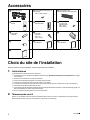
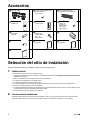
Accessoires
Choix du site de l’installation
Avant de choisir le site de l’installation, obtenez l’approbation de l’utilisateur.
1. Unité intérieure
L’unité intérieure doit être placée dans un endroit où:
1) les restrictions sur les conditions d’installation spécifiées dans “Schéma d’installation de l’unité intérieure” à la page
4 sont remplies,
2) l’entrée d’air et la sortie d’air ne sont pas obstruées,
3) l’unité n’est pas directement exposée à la lumière directe du soleil,
4) l’unité se trouve éloignée de toute source de chaleur ou de vapeur,
5) il n’existe aucune source de vapeur d’huile de mouvement (cela peut raccourcir la durée de vie de l’unité intérieure),
6) l’air froid/chaud est distribué dans toute la pièce,
7) l’unité est éloignée des lampes fluorescentes de type allumage électronique (onduleur ou type de démarrage rapide), car
elles peuvent affecter la portée de la télécommande,
8) aucun équipement de blanchisserie ne se trouve à proximité.
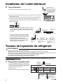
2. Télécommande sans fil
Allumez, le cas échéant, toutes les lampes fluorescentes dans la pièce, et trouvez un emplacement où les signaux de la
télécommande sont bien reçus par l’unité intérieure (à moins de 19-11/16ft (6m)).
Plaque de montage
1
Vis de fixation de la plaque de
montage
M4 × 1” (M4 × 25mm)
5
Filtre purificateur d’air
photocatalytique à apatite de titane
2
Télécommande
sans fil
1
Support de la
télécommande
1
Vis de fixation
du support de
télécommande
M3 × 13/16”
(M3 × 20mm)
2
Pile sèche
AAA. LR03
(alcaline)
2
Vis de fixation
de l’unité
intérieure
M4 × 1/2”
(M4 × 12mm)
2
Cache-vis
2
Ruban isolant
1
Manuel
d’utilisation
1
Manuel
d’installation
1
Garantie
1
A
B
C
D
E
F
G
H
J
K
L
M
N
02_FR_3P436087-1.fm Page 3 Thursday, June 9, 2016 3:59 PM

Français■
4
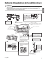
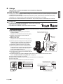
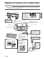
Schéma d’installation de l’unité intérieure
ATTENTION
• Ne pas donner de coup ou pousser violemment le capteur ŒIL INTELLIGENT. Cela peut conduire à des dommages et des
dysfonctionnements.
• Ne pas placer de gros objets à proximité du capteur ŒIL INTELLIGENT. Gardez aussi les unités de chauffage ou les
humidificateurs à l’extérieur de la zone de détection du capteur.
Enroulez le tuyau d’isolation avec
le ruban de finition de bas en haut.
Grille avant
Crochet
Cadre inférieur
Avant de visser le
support de la
télécommande sur le
mur, assurez-vous
que les signaux de
commande sont
correctement reçus
par l’unité intérieure.
Couvercle d’entretien
Le couvercle d’entretien est amovible.
Méthode d’ouverture
1)
Retirez les vis du couvercle d’entretien.
2)
3)
Tirez vers le bas.
Coupez le tuyau d’isolation thermique à
une longueur appropriée et enveloppez-le
de ruban adhésif, en faisant en sorte
qu’aucun espace ne soit laissé dans la
ligne de coupe du tuyau d’isolation.
1-3/16” (30mm) ou plus
du plafond
Panneau avant supérieur
1-15/16” (50mm) ou plus
des murs (des deux côtés)
Cadre du filtre
Languette
Griffe
Filtre purificateur d’air
photocatalytique à
apatite de titane
Filtre à air
Filtres à air
Vis M4 × 5/8” (M4 × 16mm)
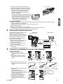
C Filtre purificateur d’air photocatalytique
à apatite de titane (2)
D Télécommande sans fil
E Support de la
télécommande
Lors du démontage de la grille avant, se référer à
“2. Retrait et installation de la grille avant” à la
page 11.
A Plaque de
montage
Capteur ŒIL INTELLIGENT
Cache-vis
J
A Plaque de montage
Comment fixer l’unité intérieure
Accrochez les crochets du cadre
inférieur à la plaque de montage.
Si les crochets sont difficiles à
accrocher, retirez la grille avant.
A
Comment retirer l’unité intérieure
Poussez la partie inférieure de la
grille avant pour libérer les crochets.
Si c’est difficile à libérer, retirez la
grille avant.
Vis de fixation de la plaque de
montage M4 × 1” (M4 × 25mm)
B
F Vis de fixation du support
de télécommande
M3 × 13/16” (M3 × 20mm)
E
Panneau avant
inférieur
19-11/16” (500mm)
ou plus
Assurez-vous qu’il n’y a pas
d’obstacle au sein de 19-11/16 inch
(500mm) sous le récepteur de
signal.
De tels obstacles, le cas échéant,
peuvent avoir une influence
défavorable sur les performances de
réception du récepteur et la distance
de réception peut être raccourcie.
Retirez le couvercle d’entretien en
diagonale vers le bas dans le sens
de la flèche.
A
La plaque de montage
doit être installée sur une
paroi pouvant supporter le
poids de l’unité intérieure.
02_FR_3P436087-1.fm Page 4 Thursday, June 9, 2016 3:59 PM

Français■
5
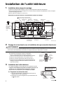
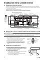
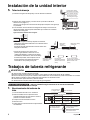
Installation de l’unité intérieure
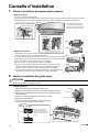
1. Installation de la plaque de montage
La plaque de montage doit être installée sur une paroi pouvant supporter le poids de l’unité intérieure.
1)Fixez provisoirement la plaque de montage au mur, assurez-vous que le panneau est parfaitement à niveau, et marquez
les points de perçage sur le mur.
2)Fixez la plaque de montage au mur avec les vis.
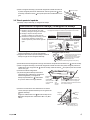
Dimensions et points de rétention recommandés de la plaque de montage
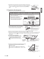
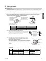
2.
Perçage d’un trou dans le mur et installation du tuyau encastré dans le mur
AVERTISSEMENT
Pour les murs à charpente ou panneau métallique, assurez-vous d’utiliser un tuyau encastré dans le mur et un couvercle d’orifice
de paroi dans l’orifice d’alimentation transversal pour empêcher toute chaleur, électrocution ou incendie.
• Assurez-vous de calfeutrer les interstices autour des tuyaux avec
des matériaux de colmatage pour éviter la condensation.
1)
Percez un orifice d’alimentation transversal d’un diamètre de
2-9/16 inch (65mm) dans le mur à un angle descendant vers l’extérieur.
2) Insérez un tuyau encastré dans le mur à l’intérieur du trou.
3) Insérez un couvercle d’orifice de paroi dans le tuyau du mur.
4) Après avoir terminé l’installation de la tuyauterie de réfrigérant, le
câblage et la tuyauterie d’évacuation, calfeutrez l’écart de trou du
tuyau avec du mastic.
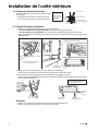
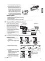
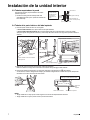
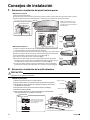
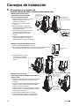
3. Installation de l’unité intérieure
• La méthode d’installation recommandée est avec la tuyauterie à l’arrière.
• Lorsque le raccordement de la tuyauterie est effectué par le bas ou la
gauche, voir “3-4. Tuyauterie du bas ou de gauche” à la page 7.
• Le raccordement à la tuyauterie ne peut être effectué du côté droit.
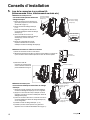
3-1. Tuyauterie du côté arrière droit
1) Fixez le tuyau d’évacuation à la partie inférieure des tuyaux de
réfrigérant avec du ruban vinyle adhésif.
2) Enveloppez les tuyaux de réfrigérant et le tuyau d’évacuation avec
du ruban isolant.
Points de rétention recommandés de la
plaque de montage (5 points dans chacune)
(Taille du boulon:
3/8 (M10))
(Taille du boulon:
3/8 (M10))
Extrémité du
tuyau de gaz
Extrémité du
tuyau de liquide
Placez un vérin sur
ces languettes.
Trou à travers le mur
φ2-9/16 (65)
unité: inch (mm)
Position du
tuyau
d’évacuation
Placez le couvercle
d’orifice de tuyau
dans cette poche.
39-5/16 (998)
14-1/16 (357)
5-5/16 (135)5-9/16 (142)
13-11/16 (348)
6-5/16 (160) 5-15/16 (151)
1-15/16
(49)
3-15/16
(100)
7-7/8 (200)
4-7/8 (124)
11-15/16 (303)
1-15/16
(49)
1-15/16
(50)
8 (203) 9-3/16 (234)
2-5/8
(67)
Utilisez un
ruban à mesurer,
comme illustré.
Positionnez
l’extrémité du
ruban à mesurer
sur .
À l’intérieur À l’extérieur
Colmater
(non fourni)
Tuyau encastré
dans le mur
(non fourni)
Couvercle
d’orifice de paroi
(non fourni)
φ2-9/16”
(65mm)
Tuyauterie du côté
arrière gauche
Tuyauterie du
côté arrière droit
Attachez le tuyau de réfrigérant et le
tuyau d’évacuation ensemble avec
du ruban adhésif en vinyle.
K
02_FR_3P436087-1.fm Page 5 Thursday, June 9, 2016 3:59 PM
La page charge ...
La page charge ...
La page charge ...
La page charge ...
La page charge ...
La page charge ...
La page charge ...
La page charge ...
La page charge ...
La page charge ...
La page charge ...
La page charge ...
La page charge ...
La page charge ...
La page charge ...
La page charge ...
La page charge ...
La page charge ...
La page charge ...
La page charge ...
La page charge ...
La page charge ...
La page charge ...
La page charge ...
-
 1
1
-
 2
2
-
 3
3
-
 4
4
-
 5
5
-
 6
6
-
 7
7
-
 8
8
-
 9
9
-
 10
10
-
 11
11
-
 12
12
-
 13
13
-
 14
14
-
 15
15
-
 16
16
-
 17
17
-
 18
18
-
 19
19
-
 20
20
-
 21
21
-
 22
22
-
 23
23
-
 24
24
-
 25
25
-
 26
26
-
 27
27
-
 28
28
-
 29
29
-
 30
30
-
 31
31
-
 32
32
-
 33
33
-
 34
34
-
 35
35
-
 36
36
-
 37
37
-
 38
38
-
 39
39
-
 40
40
-
 41
41
-
 42
42
-
 43
43
-
 44
44


GOODMAN CTXG12QVJUS Guide d'installation
- Catégorie
- Climatiseurs split-system
- Taper
- Guide d'installation
- Ce manuel convient également à
dans d''autres langues
Autres documents
-
McQuay M5WMY10KR Guide d'installation
-
Panasonic CS-E24RKUAW Guide d'installation
-
-
Daikin FTXB12AXVJU Guide d'installation
-
NAPOLEON NC19-24F-I-B Manuel utilisateur
-
-
Fujitsu ASAG07LMCA Guide d'installation
-
Mitsubishi Mr.Slim PKA-A.HA4 Guide d'installation
-
Mitsubishi Electric City Multi PKFY-P24 NFMU-E Guide d'installation
-