
Strömslingeomvandlare
Current Loop Converter (TTY)
Stromschleifenwandler
Convertisseur Boucle de Courant
INSTALLATIONSANVISNING
INSTALLATION MANUAL
INSTALLATIONS ANLEITUNG
MANUEL D’INSTALLATION
6029-2002
www.westermo.se
MA-29
©
Westermo Teleindustri AB • 1999 • REV. C
Galvanic
Isolation
Transient
Protection
CE
Approved

2 6029-2002
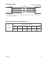
Specifikationer
Överföring Asynkront, full/halv duplex eller simplex
Gränssnitt 1 EIA RS-232-C/ITU-T V.24/V.28
25-polig D-sub hylsdon, DCE
Gränssnitt 2 20mA strömslinga, valbar aktiv eller passiv.
Överföringshastighet Upp till 19 200 bit/s
Lysdioder RD, TD, +12 V, –12 V
Isolation Fullständig galvanisk isolation med optokopplare
(dataöverföring)
Isolationsspänning 1 500 V
Överspänningsskydd Genombrottsspänning sändare och mottagare 37 V.
Avledningsförmåga 0,6 kW under 1 ms.
Strömförsörjning Externt genom PS-02 monterad i ramverk (RV-01).
±20V DC ±20%
Säkring 2 st 100 mA snabb 5x20 mm
Effektförbrukning +20 V 45 mA, –20 V 45 mA
Temperaturområde 5–50°C, omgivningstemperatur
Fuktighetsområde 0–95% RH, utan kondensation
Mått 100x100 mm
Vikt 0,1 kg
Montering I ramverk RV-01, upptar en kortplats.

36029-2002
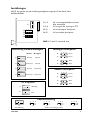
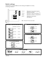
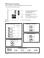
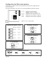
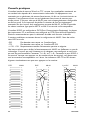
Inställningar
MA-29 kan genom en rad inställningsmöjligheter anpassas till ett flertal olika
driftförhållanden.
S1:1–2 Val av mottagare/sändare normal
eller inverterad
S1:3–4 Val av signal för styrning av CTS
S2–S3 Val av mottagare aktiv/passiv
S4–S5 Val av sändare aktiv/passiv
OBS! S1:5 och S1:6 används inte.
S1
S3
321
S2
S5
S4
Invertering Sändare/Mottagare
Mottagare aktiv/passiv
Fabriksinställning
Sändare
Normal
Normal
Inverterad
Inverterad
Inverterad
Normal
Inverterad
Mottagare
S2
CTS styrd av
Alltid hög
S1
S1
Sändare och mottagare passivCTS alltid hög
RTS
S1
Passiv
S2
Aktiv
S3
Passiv
S3
Aktiv
1
2
3
Sändare aktiv/passiv
S4
Passiv
S4
Aktiv
S5
Passiv
S5
Aktiv
1
2
3
ON
123456
ON
123456
ON
123456
ON
123456
ON
123456
ON
123456
ON
123456
S1
S1
S1
S1
Normal
ON
123456
S2
S3
1
2
3
S4
S5
1
2
3
1
2
3
1
2
3

4 6029-2002
1
2345
1
2
3
4
5
1
13 25
14
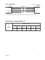
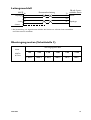
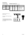
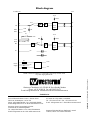
Mottagare 1 R+
Mottagare 2 R-
Sändare 3 T+
Sändare 4 T-
5 Skärm
Ansl.
nr.
I 2 103 TD/Transmitted Data
O 3 104 RD/Received Data
I 4 105 RTS/Request To Send
O 5 106 CTS/Clear To Send
O 6 107 DSR/Data Set Ready
– 7 102 SG/Signal Ground
O 8 109 DCD/Data Carrier Detect
I=ingång O=utgång i MA-29
Riktning
Benämning
Beskrivning
Riktning
Stift
nr.
ITU-T V.24
Benämning
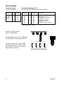
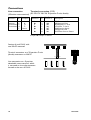
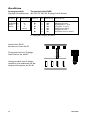
Anslutningar
Linjeanslutning
(5-polig skruvplint)
Terminalanslutning (DCE)
(RS-232-C/V, 24/V.28, 25-polig D-sub, hylsdon)
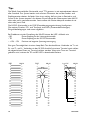
Sektion av RV-01 med en
MA-29 sedd bakifrån.
Terminalanslutning sker till en 25-polig
D-sub (hylsdon) monterad på MA-29.
Linjeanslutningen sker till en 5-polig
frånskiljbar skruvplint. Denna trycks
fast i hylsdelen, som är monterad på
bakplanskortet i RV-01.

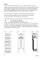
20mA strömslinge-
utrustning
600
6 000 m
Kabel
42pF/m
0,3 mm
2
56029-2002
5
Linjekoppling
Sändare
Mottagare
Mottagare
Sändare
Skärm*
4
3
2
1
R+
R–
T+
T–
T+
T–
R+
R–
MA-29
Tvinnade trådpar
* Om skärmad kabel används, anslut skärmen endast i en ände för att undvika jordströmmar.
Överföringsavstånd (gränssnitt 2)
Överföringshastighet bit/s
1 200
5 000 m
2 400
4 000 m
4 800
3 000 m
9 600
500 m
19 200
200 m

6 6029-2002
Tips
Gränssnittet 20 mA strömslinga, ibland även kallat TTY, bygger på att det finns en ström-
generator som antingen genererar en ström på ett trådpar eller är avslagen. En ström-
generator finns i vardera sändningsriktningen. Därför krävs det att man vet om omvand-
laren skall generera (aktiv) eller enbart detektera (passiv) en ström på sändar- respektive
mottagartrådparet. Aktiv sändare på MA-29 ger en passiv mottagare på motstående
strömslingeutrustning och vise versa.
RS-232 gränssnittet på MA-29 är DCE (Data Communication Equipment), vilket är det
vanliga hos kommunikations- utrustning, ex. modem. Andra utrustningar kan vara av typ
DTE (Data Terminal Equipment), ex. PC, terminaler och skrivare. Nedan visas förslag till
standardkablage.
Om det uppkommer något problem vid inkoppling av MA-29 kan lysdiodsindikeringarna
vara till värdefull hjälp vid felsökning.
• RD: Indikerar mottagen data på linjesidan.
• TD: Indikerar mottagen data på RS-232 sidan.
• +12 V, –12 V: Indikerar positiv resp. negativ matningsspänning.
Ett bra sätt att testa omvandlaren är att ansluta den mot en terminal och samtidigt bygla
linjen, T+ byglas till R+ och T- till R–. Omvandlaren konfigureras: sändare aktiv och mot-
tagare passiv eller sändare passiv och mottagare aktiv. Det tecken som nu skickas av ter-
minalen skall nu ekas tillbaka.
1
2
3
4
5
6
7
8
9
10
11
12
13
14
15
16
17
18
19
20
21
22
23
24
25
1
2
3
4
5
6
7
8
9
1
2
3
4
5
6
7
8
9
10
11
12
13
14
15
16
17
18
19
20
21
22
23
24
25
1
2
3
4
5
6
7
8
9
10
11
12
13
14
15
16
17
18
19
20
21
22
23
24
25
1
2
3
4
5
6
7
8
9
10
11
12
13
14
15
16
17
18
19
20
21
22
23
24
25
1
2
3
4
5
6
7
8
9
10
11
12
13
14
15
16
17
18
19
20
21
22
23
24
25
DTE MA-29 DCE MA-29 9-pol PC MA-29

76029-2002
ANTECKNINGAR
.....................................................................................................................................................................................................................
.....................................................................................................................................................................................................................
.....................................................................................................................................................................................................................
.....................................................................................................................................................................................................................
.....................................................................................................................................................................................................................
.....................................................................................................................................................................................................................
.....................................................................................................................................................................................................................
.....................................................................................................................................................................................................................
.....................................................................................................................................................................................................................
.....................................................................................................................................................................................................................
.....................................................................................................................................................................................................................
.....................................................................................................................................................................................................................
.....................................................................................................................................................................................................................
.....................................................................................................................................................................................................................
.....................................................................................................................................................................................................................

Specifications
Transmission Asynchronous, full/half duplex or simplex
Interface 1 EIA RS-232-C/ITU-T V.24/V.28
25-position D-sub female, DCE
Interface 2 20 mA current loop, selectable active or passive
Data rate Up to 19 200 bit/s
Indicators RD, TD, +12V, –12V
Isolation Galvanic isolation with opto-coupler (data transmission)
Isolation voltage 1 500 V
Overvoltage protection Breakdown voltage transmitter and receiver 37 V
Surge capacity 0.6 kW for 1 ms
Power supply External through PS-02 mounted in rack RV-01.
±20V DC ±20%
Fuse 2 pcs 100 mA fast 5x20 mm
Power consumption +20 V 45 mA, –20 V 45 mA
Temperature range 5–50°C, ambient temperature
Humidity 0–95% RH, non-condensing
Dimensions 100x100 mm
Weight 0.1 kg
Mounting To be mounted in rack RV-01, takes one card slot.
8 6029-2002

96029-2002
Switch settings
The MA-29 can through different switch settings be adapted to a vareity
of running conditions.
S1:1–2 Selection of transmitter/receiver
normal or inverted
S1:3–4 Selection of signal controlling CTS
S2–S3 Selection of receiver active/passive
S4–S5 Selection of transmitter
active/passive
n.b. S1:5 and S1:6 are not used.
Inverted Transmitter/Receiver
Receiver active/passive
Factory settings
Transmitter
Normal
Normal
Inverted
Inverted
Inverted
Normal
Inverted
Receiver
S2
CTS controlled by
Always high
S1
S1
transmitter and receiver always passiveCTS always high
RTS
S1
Passive
S2
Active
S3
Passive
S3
Active
1
2
3
Transmitter activ/passive
S4
Passive
S4
Active
S5
Passive
S5
Active
1
2
3
ON
123456
ON
123456
ON
123456
ON
123456
ON
123456
ON
123456
ON
123456
S1
S1
S1
S1
Normal
S2
S3
1
2
3
S4
S5
1
2
3
1
2
3
1
2
3
S1
S3
321
S2
S5
S4
ON
123456

10 6029-2002
1
2345
1
2
3
4
5
1
13 25
14
Receiver 1 R+
Receiver 2 R-
Transmitter 3 T+
Transmitter 4 T-
5 Shield
No.
I 2 103 TD/Transmitted Data
O 3 104 RD/Received Data
I 4 105 RTS/Request To Send
O 5 106 CTS/Clear To Send
O 6 107 DSR/Data Set Ready
– 7 102 SG/Signal Ground
O 8 109 DCD/Data Carrier Detect
I=Input O=Output on MA-29
Direction
Description
Description
Direction
Pin
no.
ITU-T V.24
Circuit no.
Connections
Line connection
(5-Position screw-terminal)
Terminal connection (DCE)
(RS-232-C/V.24/V.28, 25-position D-sub, female)
Section of rack RV-01 with
one MA-29 mounted.
Terminal connection to a 25-position D-sub
(female) connector on MA-29.
Line connection to a 5-position
detachable screw-terminal, which
is mounted on the male connector
located at the rear of RV-01.

Line connection
20 mA current loop
equipment
116029-2002
600
6 000 m
Cable
42pF/m
0.3 mm
2
5
Transmitter
Receiver
Receiver
Transmitter
Shield*
4
3
2
1
R+
R–
T+
T–
T+
T–
R+
R–
MA-29
Twisted pairs
* If shielded cable is used, connect the shield only at one end to avoid ground currents.
Transmission range (interface 2)
Transmission rate bit/s
1 200
5 000 m
2 400
4 000 m
4 800
3 000 m
9 600
500 m
19 200
200 m

12 6029-2002
Hints
The 20 mA current loop interface, or TTY as it is sometimes known, is a popular
industrial communications standard. The system relies on a current generator running on
both the transmit and receive circuits. On each circuit it is important to have only one
current generator supplying current into that circuit. For this reason the MA-29 can
have it’s current generators set to be either active or passive. It is important to check
the state of all attached equipment to ensure correct setting on the MA-29.
The RS-232 interface is configured as DCE (Data Communication Equipment).
Most printers, PC’s and terminals are set as DTE (Data Terminal Equipment).
Some recomendation of cable configurations are given below.
If any problems do occur on set up of the MA-29, the LED’s will be helpful.
• RD: Data received on line interface.
• TD: Data received on RS-232 interface.
• +12V, –12V: Positive and negative power supply respectivly.
A good way to check the MA-29 is to carry out a loop back test. Ensure that either the
transmitter or receiver are set to active, but not both active or passive. Connect T+ to
R+ and T– to R–. Connect the RS-232 port to a terminal. When keys are pressed on
the terminal you should receive the echo on screen. The TD & RD lights will both flick-
er simultaneously as you press the keys.
1
2
3
4
5
6
7
8
9
10
11
12
13
14
15
16
17
18
19
20
21
22
23
24
25
1
2
3
4
5
6
7
8
9
1
2
3
4
5
6
7
8
9
10
11
12
13
14
15
16
17
18
19
20
21
22
23
24
25
1
2
3
4
5
6
7
8
9
10
11
12
13
14
15
16
17
18
19
20
21
22
23
24
25
1
2
3
4
5
6
7
8
9
10
11
12
13
14
15
16
17
18
19
20
21
22
23
24
25
1
2
3
4
5
6
7
8
9
10
11
12
13
14
15
16
17
18
19
20
21
22
23
24
25
DTE MA-29 DCE MA-29 9-pol PC MA-29

136029-2002
OWN COMMENTS
.....................................................................................................................................................................................................................
.....................................................................................................................................................................................................................
.....................................................................................................................................................................................................................
.....................................................................................................................................................................................................................
.....................................................................................................................................................................................................................
.....................................................................................................................................................................................................................
.....................................................................................................................................................................................................................
.....................................................................................................................................................................................................................
.....................................................................................................................................................................................................................
.....................................................................................................................................................................................................................
.....................................................................................................................................................................................................................
.....................................................................................................................................................................................................................
.....................................................................................................................................................................................................................
.....................................................................................................................................................................................................................
.....................................................................................................................................................................................................................

14 6029-2002
Technische Daten
Übertragungsarten Asynchron, Voll-/Halbduplex oder Simplex
Schnittstelle 1 EIA RS-232-C/ITU-T V.24/V.28
25polige Sub-D-Buchse, DÜE
Schnittstelle 2 20 mA Symmetrische Stromschleife
aktiv oder passiv schaltbar
Übertragungsraten bis zu 19 200 Bit/s
Leuchtdioden RD, TD, +12V, –12V
Isolation Galvanisch Isoliert mittels Optokoppler
(Datenübertragung)
Isolationsspannung 1 500 V
Überspannungsschutz Durchbruchspannung Sender 15 V und Empfänger 5,8 V
Stromstßkapazität 0,6 KW / 1 mS
Spannungsversorgung Extern über im Rack montiertes PS-02 ±20 VDC ±20%
Sicherung 2x100 mA flink, 5x20 mm
Leistungsaufnahme +20 V 45 mA, –20 V 45 mA
Umgebungstemperatur 5–50°C
Luftfeuchtigkeit 0–95%, nicht kondensierend
Abmessungen 100x100 mm
Gewicht 0,1 Kg
Installation Im Rack, benötigt einen Steckplatz im RV-01

156029-2002
DIP-Schalter Einstellung
Das MA-29 bietet verschiedene Einstellmöglichkeiten zur Abstimmung
auf verschiedenste Betriebsverhälnisse.
S1:1–2 Auswahl des Aktivierungssignal
des Senders/Empfängers
normal/invertiert
S1:3–4 Auswahl des Signals welches
CTS steuert
S2–S3 Auswahl Empfänger aktiv/passiv
S4–S5 Auswahl Sender aktiv/passiv
S1:5 und S1:6 nicht benutzt.
Sender/Empfänger Invertiert
Empfänger aktiv/passiv
Werkseinstellung
Sender
normal
normal
invertiert
invertiert
invertiert
normal
invertiert
Empfänger
S2
CTS gesteuert von
Immer aktiv
S1
S1
Sender und Empfänger immer passivCTS immer aktiv
RTS
S1
Passiv
S2
Aktiv
S3
Passiv
S3
Aktiv
1
2
3
Sender aktiv/passiv
S4
Passiv
S4
Aktiv
S5
Passiv
S5
Aktiv
1
2
3
ON
123456
ON
123456
ON
123456
ON
123456
ON
123456
ON
123456
ON
123456
S1
S1
S1
S1
normal
S2
S3
1
2
3
S4
S5
1
2
3
1
2
3
1
2
3
S1
S3
321
S2
S5
S4
ON
123456

Beschreibung
16 6029-2002
1
2345
1
2
3
4
5
1
13 25
14
Empfänger 1 R+
Empfänger 2 R-
Sender 3 T+
Sender 4 T-
5 Schirm
Nr.
I 2 103 TD/Transmitted Data
O 3 104 RD/Received Data
I 4 105 RTS/Request To Send
O 5 106 CTS/Clear To Send
O 6 107 DSR/Data Set Ready
– 7 102 SG/Signal Ground
O 8 109 DCD/Data Carrier Detect
I= Eingang O= Ausgang des MA-29
Richtung
Beschreibung
Richtung
Pin
Nr
ITU-T V.24
Bezeichnung
Anschlüsse
Leitungsanschluß
(5-polige Schraubklemme)
Terminalanschluß DÜE
(RS-232-C/V.24/V.28, 25 polige Sub-D Buchse)
Ansicht Rack RV-01
bestückt mit einem MA-29
Terminalanschluß mit 25 poliger
Sub-D Buchse des MA-29
Leitungsanschluß einer 5-poligen
steckbaren Schraubklemme auf der
Hauptanschlussplatine des RV-01.

Leitungsanschluß
20 mA Strom-
schleifen Gerät
176029-2002
600
6 000 m
Kabel
42pF/m
0,3 mm
2
5
Sender
Empfänger
Empfänger
Sender
Schirm*
4
3
2
1
R+
R–
T+
T–
T+
T–
R+
R–
MA-29
Paarverseilte Leitung
* Bei Verwendung von abgeschirmten Kabeln den Schirm nur auf einer Seite anschließen
um Erdströme zu vermeiden
Übertragungsweiten (Schnittstelle 2)
Übertragungsraten Bit/s
1 200
5 000 m
2 400
4 000 m
4 800
3 000 m
9 600
500 m
19 200
200 m

18 6029-2002
Tips
Die 20mA Stromschleifen Schnittstelle, auch TTY genannt, ist ein weitvebreitete industri-
eller Standard. Das System bezieht sich auf einen Generator der auf der Sender- und
Empfängerseite arbeitet. Auf jeder Seite ist es wichtig, daß nur einer in Betrieb ist und
Strom in das System einspeist. Aus diesem Grund können die Generatoren beim MA-29
aktiv oder passiv geschaltet werden. Somit sollten alle Geräte überprüft werden ob sie
aktiv oder passiv sind.
Die RS-232 Schnittstelle ist als DÜE (Datenübertragungseinrichtung) konfiguriert.
Die meisten Drucker, PC’s und Terminals sind DEE’s (Datenendeinrichtungen).
Einige Kabelbelegungen sind unten aufgeführt.
Bei Problemen mit der Einstellung des MA-29 können die LED´s hilfreich sein
• RD Daten Empfang an der Leitungsschnittstelle
• TD Daten Empfang an der RS-232 Schnittstelle
• +12V, –12V Positive und negative Spannungsversorgung
Eine gute Testmöglichkeit ist einen Loop-Back Test durchzuführen. Verbinden sie T+ mit
R+ und T– mit R–. Verbinden sie den RS 232 Anschluß mit einem Terminal somit sollten
die abgeschickten Daten am Terminal sichtbar werden. Wenn eine Taste am Terminal
gedrückt wird, müssen die TD und RD LED’s abwechselnd flackern.
1
2
3
4
5
6
7
8
9
10
11
12
13
14
15
16
17
18
19
20
21
22
23
24
25
1
2
3
4
5
6
7
8
9
1
2
3
4
5
6
7
8
9
10
11
12
13
14
15
16
17
18
19
20
21
22
23
24
25
1
2
3
4
5
6
7
8
9
10
11
12
13
14
15
16
17
18
19
20
21
22
23
24
25
1
2
3
4
5
6
7
8
9
10
11
12
13
14
15
16
17
18
19
20
21
22
23
24
25
1
2
3
4
5
6
7
8
9
10
11
12
13
14
15
16
17
18
19
20
21
22
23
24
25
DEE MA-29 DÜE MA-29 9-pol PC MA-29

196029-2002
EIGENE KOMMENTARE
.....................................................................................................................................................................................................................
.....................................................................................................................................................................................................................
.....................................................................................................................................................................................................................
.....................................................................................................................................................................................................................
.....................................................................................................................................................................................................................
.....................................................................................................................................................................................................................
.....................................................................................................................................................................................................................
.....................................................................................................................................................................................................................
.....................................................................................................................................................................................................................
.....................................................................................................................................................................................................................
.....................................................................................................................................................................................................................
.....................................................................................................................................................................................................................
.....................................................................................................................................................................................................................
.....................................................................................................................................................................................................................
.....................................................................................................................................................................................................................

20 6029-2002
Spécifications
Transmission Asynchrone, full/half duplex ou simplex
Interface 1 EIA RS-232-C/ITU-T V.24
Connecteur sub-D 25 points femelle DCE
Interface 2 boucle de courant 20 mA configurable active/passive
Vitesse Jusqu'à 19 200 bit/sec
Indicateurs LED Power, RD, TD, +12V, –12V
Isolation Isolation galvanique complète avec opto-coupleur
(transmission de données)
Tension d’isolement 1 500 Volts
Alimentation Externe par bloc alimentation PS-02 installé dans rack
(RV-01) +/–20 V DC +/–20%
Fusible 2 pièces 100 mA rapide 5x20 mm
Consommation +20 V 45 mA, –20V 45 mA
Gamme température 5–50°C
Humidité 0-95% RH non condensé
Dimensions 100x100 mm
Poids 0,1 kg
Fixation En rack, occupe un emplacement carte dans un rack
RV-01
La page est en cours de chargement...
La page est en cours de chargement...
La page est en cours de chargement...
La page est en cours de chargement...
La page est en cours de chargement...
La page est en cours de chargement...
La page est en cours de chargement...
La page est en cours de chargement...
-
 1
1
-
 2
2
-
 3
3
-
 4
4
-
 5
5
-
 6
6
-
 7
7
-
 8
8
-
 9
9
-
 10
10
-
 11
11
-
 12
12
-
 13
13
-
 14
14
-
 15
15
-
 16
16
-
 17
17
-
 18
18
-
 19
19
-
 20
20
-
 21
21
-
 22
22
-
 23
23
-
 24
24
-
 25
25
-
 26
26
-
 27
27
-
 28
28


Autres documents
-
 Prime-Line M 6029 Guide d'installation
-
Patton electronic TV Converter Box IC-V.24 Manuel utilisateur
-
-
Danfoss Cooling Module Guide d'installation
-
SICK M2000 Mode d'emploi
-
SBC PCD3.F1xx & PCD3.F2xx - Communication modules Le manuel du propriétaire
-
Baumer FKDM 22N1901/S14F Mode d'emploi
-
