KitchenAid KDFE454CSS0 Guide d'installation
- Catégorie
- Lave-vaisselle
- Taper
- Guide d'installation

KitchenAid _
FOR THE WAY IT'S MADE._
INSTALLATION INSTRUCTIONS
UNDERCOUNTER DISHWASHER
INSTRUCTIONS D'INSTALLATIQN
LAVE-VAISSELLE SOUS PLAN DE TRAVAIL
Table of Contents .............................................................. 2
Table des matieres .......................................................... 27
W10321621D

TABLE OF
DISHWASHER SAFETY ............................................................................... 2
INSTALLATION REQUIREMENTS ............................................................. 3
Tools and Parts ......................................................................................... 3
Location Requirements ............................................................................. 4
Drain Requirements .................................................................................. 6
Water Supply Requirements ..................................................................... 6
Electrical Requirements ............................................................................ 6
INSTALLATION INSTRUCTIONS ............................................................... 7
Prepare Cabinet Opening--Existing Utilities ............................................ 7
Prepare Cabinet Opening--New Utilities ................................................. 7
Prepare and Route Water Line ................................................................. 8
Install Drain Hose ...................................................................................... 9
Install Moisture Barrier (under a wood countertop) ................................ 11
Prepare Dishwasher ................................................................................ 11
Make Power Supply Cord Connection ................................................... 12
CONTENTS
Determine Cabinet Opening ................................................................... 14
Install Door Handle (on some models) ................................................... 15
Custom Panel Dimensions ..................................................................... 15
Install Custom Panel ............................................................................... 15
Choose Attachment Option .................................................................... 17
Prepare Water Supply Line..................................................................... 18
Move Dishwasher Close to Cabinet Opening ........................................ 18
Connect to Water Supply ....................................................................... 21
Connect to Drain ..................................................................................... 21
Make Direct Wire Electrical Connection ................................................. 22
Secure Dishwasher in Cabinet Opening ................................................ 23
Complete Installation .............................................................................. 24
Check Operation ..................................................................................... 26
If Dishwasher Does Not Operate ............................................................ 26
Additional Tips ........................................................................................ 26
DISHWASHERSAFETY
Your safety and the safety of others are very important.
We have provided many important safety messages in this manual and on your appliance. Always read and obey all safety
messages.
This is the safety alert symbol.
This symbol alerts you to potential hazards that can kill or hurt you and others.
All safety messages will follow the safety alert symbol and either the word "DANGER" or "WARNING."
These words mean:
You can be killed or seriously injured if you don't immediately
follow instructions.
You can be killed or seriously injured if you don't follow
instructions.
All safety messages will tell you what the potential hazard is, tell you how to reduce the chance of injury, and tell you what can
happen if the instructions are not followed.
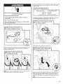
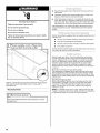
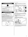
Tip Over Hazard
Do not use dishwasher until completely installed.
Do not push down on open door.
Doing so can result in serious injury or cuts.
You Need to:
• Slowly open dishwasher door while someone grasps the rear
of the dishwasher. Remove shipping materials, drain hose and
lower rack. Close dishwasher door until latched.
• Observe all governing codes and ordinances.
• Install this dishwasher as specified in these instructions.
• Installation should be performed by a qualified service
technician. The dishwasher must be installed to meet all
electrical and plumbing national and local codes and
ordinances.
Care shall be exercised when the appliance is installed or
removed, to reduce the likelihood of damage to the power-supply
cord.
WARNING: To reduce the risk of electric shock, fire, or injury to
persons, the installer must ensure that the dishwasher is
completely enclosed at the time of installation.
2

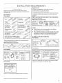
INSTALLATION
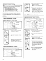
Tools and Parts
Gather the recommended tools and parts before starting
installation. Read and follow the instructions provided with any
tools listed here.
All Installations
Toolsneeded:
Piers Flat-blade
I screwdriver _
%6" and Y4" _ I UL Listed/CSA
nut drivers or _ IApproved twist-on _
hex sockets _ I wire connectors *
10" adjustable wrench_1%, omen-end
that opens to I wr^n'Zh _"
11/8 (2.9 cm) _
Torx ®*T20® and, if installing custom
front panels, Torx®T15 ®screwdrivers
*Must be the proper size to connect your household wiring to
16-gauge wiring in dishwasher.
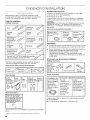
Other useful items you may need:
FI!!!_¸:i ¸/P
Parts supplied:
• ° 1 "
Dram hose Dralnhose #10x I/2 Underc0unter
Clamps (2)_ Ph Ilips: mounting
(1 large and _ head brackets(2)
3ustom
:ape (2)
Parts needed:
%" Compr X ¾" h_
For part or kit, see local
retailer or cal! Whirlpool
Parts: 1-800,442-9991. Part
Number W10273460
(4) #10 x 1/2"wood screws (if installing custom front panels)
I"®TORX, T15, and T20 are registered trademarks of Saturn Fasteners, Inc.
REQUIREMENTS
Supplied in Kit:
(4) Plastic studs (attached to each other by runners)
(4) Short screws (10-16 hex-head screw)
(4) Long screws (8-18 Torx®head screws)
(1)Template (located inside Use and Care Guide bag assembly)
(1) Instruction sheet (located inside Use and Care Guide bag
assembly)
NOTE: The screws supplied are used for only 3/4"thick wooden
panel. If the wooden panel is less than 3/4"thick, customer must
purchase screws locally.
Other parts you may also need:
I 1' " 2" Masking or' Moisture
(3.81_5 cm)duct tape barrier tape f_
I Sc[ew _type I (Part Number J_/
I 4396277)
NOTES:
• Moisture barrier tape is recommended when installing a
dishwasher under a wood countertop.
Parts available for purchase in plumbing supply stores. Check
local codes. Check existing electrical supply. See "Electrical
Requirements" section. It is recommended that electrical
connections be made by a licensed electrical installer.
In addition, for first-time installations
Toolsneeded:
I 7iL
IandIV "hole
Parts needed:
Requirements" section:
O.D.suggested) or I ........ ' _ _ _ ,
flexib e b adedlr i t-or uJrec_,vvJre', for r_ower bupply
_LeL_'stV_ Cord: use UL
d histed!CSA
strain relief Approved power
tofit%, (2,2cm) suPplycerd kit
hole marked for use With
dishwasher
Make sure all these parts are included in the literature package.
If parts are not included, call 1-800-422-1230.

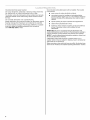
Groundedelectricalsupplyrequired.
Donotrundrainlines,waterlinesorelectricalwiringwherethey
caninterferewithorcontactdishwashermotororlegs.
Thelocationwherethedishwasherwillbeinstalledmustprovide
clearancebetweenmotorandflooring.Motorshouldnottouch
thefloor.
Donotinstalldishwasherovercarpetedflooring.
Shelterdishwasherandwaterlinesleadingtodishwasheragainst
freezing.Damagefromfreezingisnotcoveredbythewarranty.
Amoisturebarrieraccessory(PartNumber4396277)isavailable
fromyourdealerforinstallingunderneaththecountertop.
Call1-800-422-1230toorder.
Locat on Requirements
Check location where dishwasher will be installed. The location
must provide;
• easy access to water, electricity and drain.
• convenient access for loading and unloading dishes.
Corner locations require a 2" (5.1 cm) minimum clearance
between the side of the dishwasher door and the wall or
cabinet.
• square opening for proper operation and appearance.
• cabinet front perpendicular to floor.
• level floor. If floor at front of opening is not level with floor
at rear of opening, shims may be needed to level
dishwasher.
Helpful Tip: Be sure to accurately measure dimensions and
ensure dishwasher is level if the floor in the dishwasher opening is
uneven (example: Flooring extends only partway into opening).
NOTE: To avoid shifting during dishwasher operation, shims must
be securely attached to the floor.
If dishwasher will be left unused for a period of time or in a
location where it may be subject to freezing, have it winterized by
authorized service personnel.
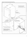
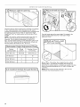
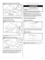
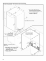
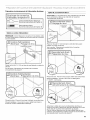
Make sure pipes, wires and drain hose are within the shaded area
shown in the "Product and Cabinet Opening Dimensions" section.

I
31/_'' . 41A"
t8.8 cm -10.6 cm)
For 4" (10 cr
kick, height of cabinet (9.
opening is 341/2'' (86.3 cm)
NOTE: Shaded areas of cabinet walls show where
utility connections may be installed.
D. Measured from the lowest point on the
underside of the countertop. May be
reduced to 33!/2" (85.1 cm) by removing
the wheels from dishwasher.
B. For panel ready models, dishwasher
depth is 24" {60 cm) not including the
3/,,. (1.9 cm) custom door panel.
C, For Pro-Style ® handle, depth is 28" (70 cm).
/ (1'_,__'
A. Insulation may
be compressed.
(not used on a I models)
Check that all surfaces
have no protrusions that wpuld
prohibit dishwasher installation.
E. Minimum, measured from narrowest point of opening.

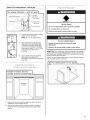
Drain Requ rements
A new drain hose is supplied with your dishwasher. If drain
hose is not long enough, use a new drain hose with a
maximum length of 12 ft (3.7 m) (Part Number 3385556) that
meets all current AHAM/IAPMO test standards, is resistant to
heat and detergent, and fits the 1" (2.5 cm) drain connector of
the dishwasher.
Make sure to connect drain hose to waste tee or disposer inlet
above drain trap in house plumbing and 20" (50.8 cm)
minimum above the floor. It is recommended that the drain
hose either be looped up and securely fastened to the
underside of the counter, or be connected to an air gap.
Make sure to use an air gap if the drain hose is connected to
house plumbing lower than 20" (50.8 cm) above subfloor or
floor.
If required, the air gap should be installed in accordance with
the air gap installation instructions. When you are connecting
the air gap, a rubber hose (not provided) will be needed to
connect to the waste tee or disposer inlet.
Water Supply Requirements
• A hot water line with 20 to 120 psi (138 to 862 kPa) water
pressure can be verified by a licensed plumber.
• 120°F (49°C) water at dishwasher.
• 3/8"O.D. copper tubing with compression fitting or flexible
braided water supply line (Part Number 4396897RP).
NOTE: 1/2"minimum plastic tubing is not recommended.
• A 90° elbow with 3/4"hose connection with rubber washer
(Part Number W10273460).
• Do not solder within 6" (15.2 cm) of the water inlet valve.
Electr cal Requ rements
Be sure that the electrical connection and wire size are adequate
and in conformance with the National Electrical Code, ANSI/NFPA
70 - latest edition and all local codes and ordinances.
A copy of the above code standards can be obtained from:
National Fire Protection Association
1 Batterymarch Park
Quincy, MA 02169-7471
You must have:
• 120-volt, 60 Hz, AC-only, 15- or 20-amp, fused electrical
supply.
• Copper wire only.
We recommend:
• A time-delay fuse or circuit breaker.
• Aseparate circuit.
If connecting dishwasher with a
power supply cord:
Use UL Listed power supply cord kit
(Part Number 4317824) marked for
use with dishwasher.
Power supply cord must plug into a grounded
3 prong outlet, located in the cabinet next to
the dishwasher opening. Outlet must meet all
local codes and ordinances.
If connecting dishwasher with direct wiring:
• Use flexible, armored or nonmetallic
sheathed, copper wire with
grounding wire that meets the
wiring requirements for your home
and local codes and ordinances.
• Use a UL Listed/CSA Approved strain relief.
6

INSTALLATION
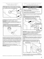
Electrical Shock Hazard
Disconnect electrical power at the fuse box or circuit
breaker box before installing dishwasher.
Failure to do so can result in death or electrical shock.
I Disc0aneCt electdcan p0we[ at the fUSe box 0r circui t
J
Do you already have utility_:,
hookups?
_Follow instruCti0ns!!n the iiPrepare Cabinet
Opening_Existing Utilities Secti:n.
NO _F011ow instructi0ns in the Prepare Cabinet
:ility hookups
INSTRUCTIONS
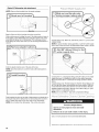
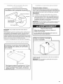
Prepare Cabinet Opening--Existing Utilit es
If the water line and the cable extend to the locations shown,
proceed to the "Install Drain Hose" section. If they do not reach far
enough, follow the instructions in the "Prepare Cabinet Opening--
New Utilities" section.
Prepare Cab net Opening--New Utilites
Prepare and route the electrical supply
What type of electrical
connection will you use?
Option A, Power Supply Cord:
NOTE: A grounded 3 prong outlet is required inside a cabinet next
to the dishwasher cabinet opening.
Drill a 11/2"(3.8 cm) hole in cabinet side or rear.
See "Product and Cabinet Opening Dimensions" section.

Woodcabinet:Sandtheholeuntilsmooth.
Metalcabinet:Coverholewithgrommetincludedwithpower
supplycordkit.
Option B, Direct Wire:
Helpful Tip: Wiring the dishwasher will be easier if you route the
cable into the cabinet opening from the right-hand side.
Drill a 1V2"(3.8 cm) hole in right-hand cabinet side or rear.
See "Product and Cabinet Opening Dimensions" section.
Wood cabinet: Sand the hole until smooth.
Metal cabinet: Cover hole with grommet (Part Number 302797 -
not provided).
Route cable from power supply through cabinet hole (cable must
extend to the right front side of cabinet opening). Tape cable to
the floor in area shown. This will prohibit cable from moving when
dishwasher is moved into cabinet opening.
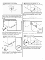
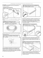
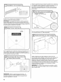
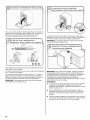
Prepare and Route Water Lne
Helpful Tip: Routing the water line through the left side of cabinet
opening will make water connection easier.
Drill a 1/2"(1.3 cm) hole in the cabinet side or rear.
(copper tubing only)
Measure overall length of copper tubing for the water supply line.
8

Attach the water supply line (copper tubing or flexible braided line)
to the hot water line using a connection configuration that is in
compliance with local codes and ordinances. The water supply to
the dishwasher should have a manual shutoff valve located under
the sink.
Slowly route water supply line through hole in cabinet. (If you are
using copper tubing, it will bend and kink easily, so be gentle.) It
should be far enough into the cabinet opening to connect it to the
dishwasher inlet on the front left side of the dishwasher.
Slowly turn water shutoff valve to "ON" position. Flush water into
a shallow pan until clear to get rid of particles that could clog the
inlet valve. Turn shutoff valve to "OFF" position.
Route water line and tape it to the floor in area shown. This will
keep it from moving when dishwasher is moved into cabinet
opening.
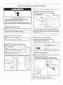
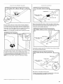
Install Dran Hose
IMPORTANT: Always use a new drain hose. Oheck local codes to
determine whether an air gap is required.
If needed, drill a 1V2"(3.8 cm) diameter hole in cabinet wall or side
of the opening closest to the sink.
Route drain hose as shown through hole in cabinet to the front
center of opening where drain connection will be made. Tape
drain hose to the floor in area shown. This will prohibit it from
moving when dishwasher is moved into cabinet opening.

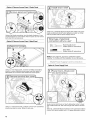
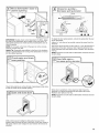
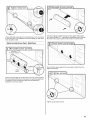
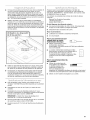
connectdrainhOsetowasteteeOrWastedispose[
using0heofthefollow!ng0pt!ons;
! OptionA,Wastedisposer-noairgap
OptionB,NoWastedisposer_aoairgap
OptionC;Wastedisposei- witha
1=
2.
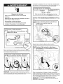
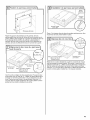
Option D, No waste disposer - with air gap
;_;,_;;;__ ;;;_;i_;11¸_;;;_ i
1. Connect rubber end of drain hose to
air gap and cut if needed.
NOTE: Do not cut ribbed section.
2=
Attach drain hose to air gap with
large drain hose clamp (provided).
Use pliers to squeeze clamp open
and move into position. If the drain
hose was cut, use a 11/2'' to 2" (3.8 to
5 cm) screw-type clamp (not
provided).
3=
Use a rubber hose (not provided)
with screw-type clamps (not
provided) to connect from waste tee
to air gap.
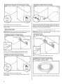
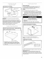
Install Mo sture Barr er
(under a wood counte¢op)
Moisture
barrier
J
Make sure the area under the cabinet is clean and dry for
installation of the moisture barrier.
Remove the backing of the moisture barrier and apply to
underside of the countertop along the front edge of the
counter.
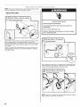
Prepare D shwasher
Tip Over Hazard
Do not use dishwasher until completely installed.
Do not push down on open door.
Doing so can result in serious injury or cuts.
Excessive Weight Hazard
Use two or more people to move and install
dishwasher.
Failure to do so can result in back or other injury.
Helpful Tip: Place cardboard under dishwasher until installed in
cabinet opening to avoid damaging floor covering. Do not use
door panel as a worktable without first covering with a towel to
avoid scratching the door panel.
Using 2 or more people, grasp sides of dishwasher door frame
and place dishwasher on its back.
11

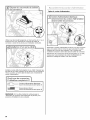
Option A, Remove Access Panel - Plastic Panel
Using a flat-blade screwdriver, turn the plastic fasteners 1/4turn
counterclockwise to unlock them. Remove panel. Do not remove
tech sheet from access panel.
Option B, Remove Access Panel - Metal Panel
Using a 1/4"hex-head socket, nut driver or Phillips screwdriver,
remove 2 screws attaching access panel and lower panel to
dishwasher. Do not remove tech sheet from access panel.
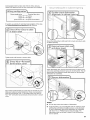
® ®
Using a 1/4"hex-head socket, nut driver or Torx T20 screwdriver,
remove terminal box cover. Retain for later use.
Install a UL Listed/CSA Approved strain relief. Make sure screw
heads are facing to the left when tightening conduit nut. Strain
relief is provided with the power supply cord kit.
What type of electrical
connection will you use?
NOTE: If using Option B, proceed to "Determine Cabinet
Opening," to continue with the installation of your dishwasher.
Make Power Suppy Cord Connect on
Option A, Power Supply Cord:
Route cord so that it does not touch dishwasher motor to lower
part of dishwasher tub. Pull cord through strain relief in terminal
box.
Select UL Listed/CSA Approved twist-on wire connectors rated to
connect your power supply cord to 16-gauge dishwasher wiring.
12

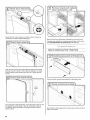
Electrical Shock Hazard
ElectricMly ground dishwasher.
Connect ground wire to green ground connector in
terminal box.
Do not use an extension cord.
Failure to follow these instructions can result in death,
fire, or electrical shock.
Connect ground wire
....
o
I Jl v Iff_,:Y_ _ wire , - "-','_y,,'_ "
kkW / ? w're
_ashe
Remove the ground connector screw and place through the ring
terminal of the green ground wire. Reattach and tighten the
ground connector screw.
)
NOTE: Do not pre-twist stranded wire. Twist on wire connector.
Gently tug on wires to be sure both are secured.
Connect wires black to black and white to white, using UL Listed/
CSA Approved twist-on wire connectors (included with power
supply cord kit).
If needed, see website for animated representation of this step.
Visit www.kitchenaid.com/electrical under FAQ tab.
Tighten strain relief screws to secure cord.
Place wires inside terminal box. Insert tabs on left side of cover.
Make sure wires are tucked inside box. Close cover ensuring
wires are not pinched. Use 1/4"hex-head socket, nut driver or
Torx®T20 ®screwdriver and previously removed screw to secure
cover.
NOTE: Do not plug into outlet until instructed to do so.
13

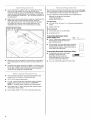
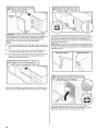
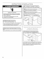
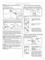
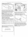
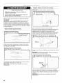
Determine Cab net Opening
Measure height of cabinet opening from underside of countertop
to floor where dishwasher will be installed (you will need to
measure the lowest point on the underside of the countertop and
the highest point on the floor). Refer to "Dishwasher Height
Adjustment Chart" for wheel position and the number of turns
needed.
NOTE: If the minimum cabinet opening height is less than 34"
(86.4 cm), the rear wheels can be removed for additional
clearance. This will allow the dishwasher to fit into a 337/2''
(85.1 cm) high cabinet opening, but the dishwasher will be more
difficult to move. Measurements are approximate. Wheels and
legs are preset at the factory for 341/2"(87.6 cm).
opening height position on front leg
331/2'; (85'1 cm) Removed All the way uP
I
341/4'!(87"0 cm) I 2 5
I
34W! (87,6 cm)3 0 .....
Turn both leveler legs to the same height. Put wheels in the
required position determined from "Dishwasher Height
Adjustment Chart."
Built-up floors: If the kitchen floor is higher than the cabinet
opening's floor - for example, the kitchen floor tile does not
extend into the cabinet opening - add shims as needed in the area
shown to bring the dishwasher up to 34" (86.4 cm) below the
countertop.
NOTE: Shims must be securely attached to floor to avoid
movement when the dishwasher is in use.
14

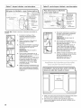
Install Door Handle
(onsore÷models)
Install door
Handle
Setscrew
(in bottom
of handle)
Hex key
IMPORTANT: Do not scratch the front panel during this
procedure.
Remove the door handle and hardware bag containing the
setscrews and hex key from the cardboard box. Setscrews are
already installed in the handle. Place handle on mounting studs
with the setscrews facing down. Push the door handle tightly
against the door. Insert the short end of the hex key into the
setscrews. Tighten the setscrews 1/4turn past snug.
Retain hex key with Installation Instructions.
Custom Panel Dimensions
with control panel on the top
,
(60 cm) ! 29 Y32'(76 cm)
¾" (19.1 mm)
* This dimension is for 4" (10.2 cm) toe kick. If the
installation needs a higher toe kick, adjust the height
of the wood panel accordingly except on models with
ProDry TM. Not recommended for toe kicks greater than
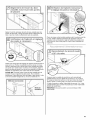
Install Custom Panel
Follow steps below:
A customer supplied panel must weigh no more than 16 Ibs
(7.3 kg) and must be made to specific dimensions. It is
recommended that a cabinetmaker cut the customer panel
because of the precise dimensions needed.
NOTES:
• The handle for the custom panel is not included.
All mounting hardware supplied is for a 3/4"(19.1 mm) thick
wood panel. If a thinner wood panel or materials other than
wood are used, it is the customer's responsibility to obtain the
proper length screws and adjust the pilot holes accordingly.
IMPORTANT: Use a moisture-resistant sealer on both sides and
all edges of the panel to avoid damage from moisture.
Excessive Weight Hazard
Use two or more people to move and install
dishwasher.
Failure to do so can result in back or other injury.
Stand dishwasher upright
Using 2 or more people, stand the dishwasher up.
NOTE: Do not install kick plate until instructed to do so.
Install the custom hardware handle(s) on the front of the wooden
panel inside dotted line.
IMPORTANT: If the handle is attached from the back of the
custom panel, the screw holes should be countersunk for the
screws heads to be flush with the panel. If the handle is attached
to the front of the custom panel, the screw lengths cannot exceed
the panel thickness.
15

TopOfP.nel
Tapad_ p.nel
Dessusdup.nn_au
cent_dlne
u_ea cen_l
Ax__ntr_l
r
Using the template provided, attach it to the backside of the
custom panel with tape. Make sure that the center of the template
is aligned with the center of the wooden panel and top of the
template is aligned to the top face of the wooden panel.
_J
NOTE: Do not drill deeper then %" (16 mm) to keep from drilling
through panel. Pilot hole depths given are for 3/4"(19 ram) thick
panel.
Mark 4 pilot holes on the wooden panel using the template
provided. Predrill 4 pilot holes using a 3/32"drill bit. Use tape to
mark the drill bit to gauge hole depth. Drill pilot holes
approximately %" (16 mm)into the custom panel.
Visible side
Attach the 4 plastic studs to the wooden panel using the 4 short
hex-head (sAc")screws provided.
Attach custom tape
Check custom tape alignment with metal door slots; verify tape is
right-side up, and that the tape does not overhang the metal door
on the top, bottom or side interfaces. Remove the backing from
the custom tape by pulling straight down on the liner. Align the
custom tape to the keyhole slots on the metal door (see image)
and apply. Repeat steps for one side and then the other.
NOTE: The adhesive on the tape is aggressive, so proper
alignment and attachment to the metal door needs to occur on
the first try.
Attach custom panel
Wooden panel
assembly
Align the studs on the custom wood panel to the keyhole slots on
the door assembly. Ensure that all 4 plastic studs are engaged in
the keyhole slots. Slide wood panel down until the top surface of
the wooden panel is flush with the top of the door.
16

Customer-supplied
panel
Drill through
these holes.
Remove 2 short screws
and replace with long
screws provided.
Open the door and align top edges. Predrill 2 pilot holes using a
3/32"drill bit. Use tape to mark the drill bit to gauge hole depth. Drill
pilot holes approximately 11/2"(3.8 cm) into the top corners of the
door using hole in liner as a guide.
I
edges
)rill through
these holes
Customer-supplied
panel
Install 2 long screws supplied in top corners to secure custom
wood panel in place.
Remove the short screws
edges
Remove 2 short screws Customer-supplied
and replace with long panel
screws provided.
Remove the short screws (3rd from top) on either side of the inner
door panel. Predrill 2 pilot holes using a 3/32"drill bit. Use tape to
mark the drill bit to gauge the hole depth. Drill pilot holes
approximately 11/2"(3.8 cm) using the door liner hole as a guide
into the panel. Install the 2 remaining long screws.
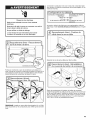
Choose Attachment Opton
Excessive Weight Hazard
Use two or more people to move and install
dishwasher.
Failure to do so can result in back or other injury.
Use 2 or more people to move and install dishwasher.
IMPORTANT: The dishwasher must be secured to the cabinet.
There are two brackets found in the parts bag. Attach the
brackets using Option A if the countertop is wood, laminate or
another similar surface. If your countertop is marble, granite or
another hard surface, install using Option B.
Option A, Countertop attachment:
Remove the brackets from the package and insert into the open
slots on the left and right-hand top of the dishwasher collar as
shown.
Using a pair of pliers, bend the tab down to secure the bracket in
place. Repeat this step for the other side.
NOTE: Do not attach the dishwasher. This will be done later.
17

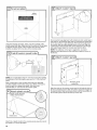
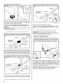
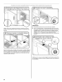
OptionB,Dishwashersideattachment:
NOTE: Removethe brackets from the parts package.
Break off the end of the bracket along the scored line.
With another person holding the rear of the dishwasher to keep it
from tipping, open dishwasher door and place towel over pump
assembly and spray arm of dishwasher. This will keep screws
from falling into pump area when you are securing dishwasher to
cabinet.
Push the plastic buttons out of the side of the tub.
NOTE: Save the buttons to cover the holes after dishwasher is
installed.
Install bracket
Push bracket into slot on the side of dishwasher, and bend tab in
toward the side of the dishwasher so that it keeps the bracket in
place. Repeat this step for the other side of the dishwasher.
NOTE: Do not attach the dishwasher. This will be done later.
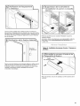
Prepare Water Supply Line
Copper tubing only: Slide nut, then ferrule, about 1" (2.5 cm) onto
copper tubing.
NOTE: To avoid vibration during operation, route the water supply
line so that it does not touch the dishwasher base, frame or motor.
Connect the 3/8"compression fitting of the 90° elbow to the water
supply line prior to installing the unit into the cabinet opening.
Attach such that the 3/4"connection is facing upward as shown
above.
Copper tubing only: Put the tubing into the 90° elbow fitting as far
as it will go (the copper tubing bends and kinks easily). Slide the
nut and ferrule forward and start the nut onto the elbow threads.
Flexible braided connection: Secure nut to elbow using 5/8"open
ended wrench or adjustable wrench.
NOTE: Do not use Teflon ®ttape with compression fittings.
Move D shwasher Close to Cab net Opening
Excessive Weight Hazard
Use two or more people to move and install
dishwasher.
Failure to do so can result in back or other injury.
Use 2 or more people to move and install dishwasher.
1-®TEFLON is a registered trademark of E.I. Du Pont De Nemours and Company.
18

IMPORTANT: Double-check correct placement of utilities. Grasp
the sides of the dishwasher at the edges of the door panel. Tilt
dishwasher backward on wheels and move dishwasher close to
cabinet opening.
NOTE: Do not push on the front of the panel or on the console.
Panel or console may dent.
Helpful Tip: Temporarily tape utilities to the floor in the locations
shown to prohibit them from moving when dishwasher is moved
into the cabinet opening.
Check that water line is on the left side of opening and drain hose
is near the center of the cabinet opening.
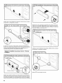
With another person holding the dishwasher to keep it from
tipping, open and close the door a few times. If the door closes or
falls open under its own weight, the door tension will need to be
adjusted.
Screw L_ _'_ _'&'_
To adjust the door spring tension, unhook the spring from the rear
leg of dishwasher.
Using a 5/16"nut driver or hex socket, remove the screw from the
tensioner.
The screw can be put into one of 3 holes (1,2, 3) in the front leg of
dishwasher. If the door closes by itself, move the tensioner to a
lower-numbered hole and replace screw. Reattach door spring to
rear leg.
NOTE: Tensioners on both sides of dishwasher should be secured
at same holes.
When door is unlatched, if door opens by itself, move the
tensioner to a higher-numbered hole and replace the screw.
Reattach door spring to rear leg.
NOTE: Tensioners on both sides of dishwasher should be secured
at same holes.
19

IMPORTANT: If wheels were removed, cover the floor when
moving the dishwasher. Slowly move dishwasher completely into
cabinet opening. Do not kink or pinch water line, drain hose,
power supply cord or direct wire between dishwasher and
cabinet. Remove cardboard from under dishwasher.
NOTES:
• It is all right if dishwasher fits tightly into cabinet opening. Do
not remove insulation blanket - the blanket reduces the sound
level.
If using power cord, make sure to route end through hole in
cutout before sliding dishwasher into cabinet opening.
For models with water softener, make sure that the drain hose
stays on the hanger that is on the right-hand side and is
tucked in on the side of the unit.
Align front of dishwasher door panel with front of cabinet doors.
You may need to adjust alignment to be even with your cabinets.
Check that leveling legs are firmly against the floor. Close and
latch the door, and place level against the front panel. Check that
dishwasher is centered from front to back in the opening. If
needed, adjust leveling leg until dishwasher is plumb. Repeat for
other side of dishwasher.
Helpful Tip: Push up on front of dishwasher to raise dishwasher
off the ground to adjust front legs. With some installations, it may
be easier to adjust the front leg using the ¾6" hex-head socket or
adjustable wrench.
Place level against top front opening of tub. Check that
dishwasher is level from side-to-side. If dishwasher is not level,
adjust front legs up or down until dishwasher is level.
2O
La page est en cours de chargement...
La page est en cours de chargement...
La page est en cours de chargement...
La page est en cours de chargement...
La page est en cours de chargement...
La page est en cours de chargement...
La page est en cours de chargement...
La page est en cours de chargement...
La page est en cours de chargement...
La page est en cours de chargement...
La page est en cours de chargement...
La page est en cours de chargement...
La page est en cours de chargement...
La page est en cours de chargement...
La page est en cours de chargement...
La page est en cours de chargement...
La page est en cours de chargement...
La page est en cours de chargement...
La page est en cours de chargement...
La page est en cours de chargement...
La page est en cours de chargement...
La page est en cours de chargement...
La page est en cours de chargement...
La page est en cours de chargement...
La page est en cours de chargement...
La page est en cours de chargement...
La page est en cours de chargement...
La page est en cours de chargement...
La page est en cours de chargement...
La page est en cours de chargement...
La page est en cours de chargement...
La page est en cours de chargement...
La page est en cours de chargement...
La page est en cours de chargement...
La page est en cours de chargement...
La page est en cours de chargement...
-
 1
1
-
 2
2
-
 3
3
-
 4
4
-
 5
5
-
 6
6
-
 7
7
-
 8
8
-
 9
9
-
 10
10
-
 11
11
-
 12
12
-
 13
13
-
 14
14
-
 15
15
-
 16
16
-
 17
17
-
 18
18
-
 19
19
-
 20
20
-
 21
21
-
 22
22
-
 23
23
-
 24
24
-
 25
25
-
 26
26
-
 27
27
-
 28
28
-
 29
29
-
 30
30
-
 31
31
-
 32
32
-
 33
33
-
 34
34
-
 35
35
-
 36
36
-
 37
37
-
 38
38
-
 39
39
-
 40
40
-
 41
41
-
 42
42
-
 43
43
-
 44
44
-
 45
45
-
 46
46
-
 47
47
-
 48
48
-
 49
49
-
 50
50
-
 51
51
-
 52
52
-
 53
53
-
 54
54
-
 55
55
-
 56
56


KitchenAid KDFE454CSS0 Guide d'installation
- Catégorie
- Lave-vaisselle
- Taper
- Guide d'installation
