Zephyr ZRO-E30DS Hood User Manual
- Catégorie
- Hottes
- Taper
- Hood User Manual
Ce manuel convient également à

Use, Care, and Installation Guide
Model Number:
Serial Number:
www.zephyronline.com
ZRO-E30DS
ZRO-M90DS
SEP18.0501 © Zephyr Ventilation LLC.
ZRV-E30BGC ZRV-M90BGC
ZRV-E30BGG ZRV-M90BGG
ZRV-E30BBSGG ZRV-M90BBSGG
ZAN-E24CS
ZAN-E30CS ZAN-E30CBS
ZAN-M90CS ZAN-M90CBS
ZSA-E30DB ZSA-E30DW
ZSA-E30DS ZSA-E30DBS
ZSA-M90DB ZSA-M90DW
ZSA-M90DS ZSA-M90DBS

www.zephyronline.com

1
SAFETY NOTICE ................................................................. 2-3
LIST OF MATERIALS ....................................................... 4
INSTALLATION
Ducting Calculation Sheet
....................................... 5
Mounting Height & Clearance
................................ 6
Ducting Options
........................................................... 7
+RRG6SHFL¿FDWLRQV
................................................... 8 - 11
Mounting the Hood
..................................................... 12
Ductless Recirculating
.............................................. 13
FEATURES & CONTROLS
ICON Touch Controls
................................................ 14 - 15
MAINTENANCE
Hood and Filter Cleaning
......................................... 16
ACT CONVERSION
..................................................................... 17
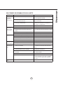
WIRING DIAGRAMS
................................................................... 18
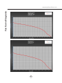
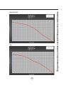
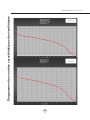
FAN CURVE DIAGRAMS
......................................................... 19 - 20
TROUBLESHOOTING
................................................................ 21
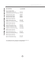
LIST OF PARTS AND ACCESSORIES
.............................. 22
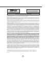
WARRANTY
.................................................................................... 23
PRODUCT REGISTRATION
.................................................... 24
Table of Contents

Important Safety Notice
READ AND SAVE THESE INSTRUCTIONS
2
www.zephyronline.com
WARNING
TO REDUCE THE RISK OF FIRE OR ELECTRIC SHOCK, DO NOT USE THIS FAN WITH ANY SOLID-STATE CONTROL DEVICE.
WARNING
TO REDUCE THE RISK OF FIRE ELECTRIC SHOCK, OR INJURY TO PERSONS, OBSERVE THE FOLLOWING:
a. Use this unit only in the manner intended by the manufacturer, if you have questions, contact the manufacturer.
b. Before servicing or cleaning unit, switch power off at service panel and lock panel to prevent power from being switched on accidentally.
When the service disconnecting means cannot be locked, securely fasten a prominent warning device, such as a tag, to the service
panel.
CAUTION
For general ventilating use only. Do not use to exhaust hazardous or explosive materials and vapors. Take care when using cleaning
agents or detergents. Suitable for use in household cooking area.
WARNING
TO REDUCE THE RISK OF RANGE TOP GREASE FIRE:
a. Never leave surface units unattended at high settings. Boilovers cause smoking and greasy spillovers that may ignite. Heat oils slowly
on low or medium settings.
E $OZD\VWXUQKRRG21ZKHQFRRNLQJDWKLJKKHDWRUZKHQÀDPLQJIRRG
F &OHDQYHQWLODWLQJIDQVIUHTXHQWO\*UHDVHVKRXOGQRWEHDOORZHGWRDFFXPXODWHRQIDQRU¿OWHU
d. Use proper pan size. Always use cookware appropriate for the size of the surface element.
H .HHSIDQ¿OWHUVDQGJUHDVHODGHQVXUIDFHVFOHDQ
f. Use high setting on hood only when necessary.
g. Don’t leave hood unattended when cooking.
h. Always use cookware and utensils appropriate for the type of and amount of food being prepared.
WARNING
TO REDUCE THE RISK OF INJURY TO PERSONS IN THE EVENT OF A RANGE TOP FIRE, OBSERVE THE FOLLOWING:
D 6027+(5)/$0(6ZLWKDFORVH¿WWLQJOLGFRRNLHVKHHWRUPHWDOWUD\WKHQWXUQRIIWKHEXUQHU%(&$5()8/7235(9(17%8516
,IWKHÀDPHVGRQRWJRRXWLPPHGLDWHO\(9$&8$7($1'&$//7+(),5('(3$570(17
b. NEVER PICK UP A FLAMING PAN – You may be burned.
c. DO NOT USE WATER, including wet dishcloths or towels – a violent steam explosion will result.
d. Use an extinguisher ONLY if:
1. You know you have a Class ABC extinguisher, and you already know how to operate it.
7KH¿UHLVVPDOODQGFRQWDLQHGLQWKHDUHDZKHUHLWVWDUWHG
7KH¿UHGHSDUWPHQWLVEHLQJFDOOHG
<RXFDQ¿JKWWKH¿UHZLWK\RXUEDFNWRDQH[LW
WARNING
TO REDUCE THE RISK OF FIRE, ELECTRIC SHOCK OR INJURY TO PERSONS, OBSERVE THE FOLLOWING:
D ,QVWDOODWLRQZRUNDQGHOHFWULFDOZLULQJPXVWEHGRQHE\TXDOL¿HGSHUVRQVLQDFFRUGDQFHZLWKDOODSSOLFDEOHFRGHVDQGVWDQGDUGV
,QFOXGLQJ¿UHUDWHGFRQVWUXFWLRQ
E 6XI¿FLHQWDLULVQHHGHGIRUSRZHUFRPEXVWLRQDQGH[KDXVWLQJRIJDVHVWKURXJKWKHÀXHFKLPQH\RIIXHOEXUQLQJHTXLSPHQWWRSUHYHQW
back-drafting. Follow the heating equipment manufacturer’s guideline and safety standards such as those published by the National
)LUH3URWHFWLRQ$VVRFLDWLRQ1)3$DQGWKH$PHULFDQ6RFLHW\IRU+HDWLQJ5HIULJHUDWLRQDQG$LU&RQGLWLRQLQJ(QJLQHHUV$6+5$(DQG
the local code authorities.
c. When cutting or drilling into wall or ceiling, do not damage electrical wiring and other hidden utilities.
d. Ducted fans must always vent to the outdoors.
e. NEVER place a switch where it can be reached from a tub or shower.
f. Make sure the power is off before installing, wiring or maintenancing.

Important Safety Notice
3
WARNING
TO REDUCE THE RISK OF FIRE, USE ONLY METAL DUCTWORK.
CAUTION
7RUHGXFHULVNRI¿UHDQGWRSURSHUO\H[KDXVWDLURXWVLGH'RQRWYHQWH[KDXVWDLULQWRVSDFHVZLWKLQZDOOVFHLOLQJV
attics, crawl spaces or garages.
Not for use over an outdoor grill.
OPERATION
$OZD\VOHDYHVDIHW\JULOOHVDQG¿OWHUVLQSODFH:LWKRXWWKHVHFRPSRQHQWVRSHUDWLQJEORZHUVFRXOGFDWFKRQWRKDLU¿QJHUV
and loose clothing.
The manufacturer declines all responsibility in the event of failure to observe the instructions given here for installation,
maintenance and suitable use of the product. The manufacturer further declines all responsibility for injury due to
negligence and the warranty of the unit automatically expires due to improper maintenance.
*NOTE: Please check www.zephyronline.com for revisions before doing any custom work.
ELECTRICAL REQUIREMENTS
Important:
Observe all governing codes and ordinances.
It is the customer’s responsibility:
7RFRQWDFWDTXDOL¿HGHOHFWULFDOLQVWDOOHU
- To assure that the electrical installation is adequate and in conformance with National Electrical Code, ANSI/NFPA 70
latest edition* or CSA standards C22.1-94, Canadian Electrical Code, Part 1 and C22.2 No.0-M91 - latest edition** and
all local codes and ordinances.
,IFRGHVSHUPLWDQGDVHSDUDWHJURXQGZLUHLVXVHGLWLVUHFRPPHQGHGWKDWDTXDOL¿HGHOHFWULFLDQGHWHUPLQHWKDWWKH
ground path is adequate.
Do not ground to a gas pipe.
&KHFNZLWKDTXDOL¿HGHOHFWULFLDQLI\RXDUHQRWVXUHWKHUDQJHKRRGLVSURSHUO\JURXQGHG
Do not have a fuse in the neutral or ground circuit.
*National Fire Protection Association Batterymarch Park, Quincy, Massachusetts 02269
** CSA International 8501 East Pleasant Valley Road, Cleveland, Ohio 44131-5575
This appliance requires a 120V 60Hz electrical supply and connected to an individual properly grounded branch circuit
protected by a 15 or 20 ampere circuit breaker or time delay fuse. Wiring must be 2 wire with ground. Please also refer to
Electrical Diagram on product.
$FDEOHORFNLQJFRQQHFWRUQRWVXSSOLHGPLJKWDOVREHUHTXLUHGE\ORFDOFRGHV&KHFNZLWKORFDOUHTXLUHPHQWVSXUFKDVH
and install appropriate connector if necessary.

4
www.zephyronline.com
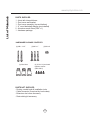
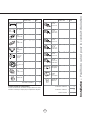
(3) Wire Nuts
(2) M6 x 1-1/2”
(3) M6 x 1”
(2) M4 x 8
PARTS NOT SUPPLIED
- Ducting, conduit and all installation tools
- Cable connector (if required by local codes)
- Extension duct cover accessory
- Recirculating kit accessory
HARDWARE PACKAGE CONTENTS
PARTS SUPPLIED
1 - Hood with internal blower
1 - Duct cover wall bracket
1 - Duct cover assembly (top and bottom)
1 - 6” round backdraft damper (pre-installed)
2 - Aluminum mesh filters (ZRV x 1)
1 - Hardware package
(4) 3/16 x 1/4 pan-head
machine screws
(ZRV ONLY)
List of Materials

5
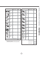
Duct pieces
Tot a l
Equivalent number
length x used =
3- 1/4” x 10”
Rect.,
straight
1 Ft. x ( ) =
Ft.
3- 1/4” x 10”
Rect. to
6” round
transition
5 Ft. x ( ) =
Ft.
3- 1/4” x 10”
Rect. to
6” round
transition
90
0
elbow
20 Ft. x ( ) =
Ft.
6”, 7”, 8”, 10”
Round,
90
0
15 Ft.
x ( ) =
Ft.
6”, 7”, 8”, 10”
Round,
45
0
9 Ft. x ( ) =
Ft.
Ft.
6”, 7”, 8”, 10”
Round,
straight
1 Ft. x ( ) =
Ft.
Subtotal column 1 =
Duct pieces
Tot a l
Equivalent number
length x used =
6”, 7”, 8”, 10”
Round, wall
cap with
damper
30 Ft. x ( ) =
Ft.
Ft.
Ft.
Ft.
6”, 7”, 8”, 10”
Round
roof cap
30 Ft. x ( ) =
Ft.
Subtotal column 2 =
Subtotal column 1 =
Total ductwork =
Maximum Duct Length: For satisfactory air movement,
the total duct length
should not exceed 100 equivalent feet.
6” round to
3- 1/4” x 10”
rect.
transition
1 Ft. x ( ) =
Ft.
6” round to
3- 1/4” x 10”
rect.
transition
90
0
elbow
16 Ft. x ( ) =
Ft.
7” round to
3 1/4” x 10”
rect.
transition
8 Ft. x ( ) =
Ft.
7” round to
3- 1/4” x 10”
rect.
transition
90
0
elbow
23 Ft. x ( ) =
Ft.
elbow
elbow
7” to 6” or
8” to 7” Round
tapered
reducer
25 Ft. x ( ) =
Ft.
3- 1/4” x 10”
Rect. 90
0
elbow
15 Ft. x ( ) =
Ft.
3- 1/4” x 10”
Rect. 45
0
elbow
9 Ft. x ( ) =
Ft.
3- 1/4” x 10”
Rect. 90
0
flat elbow
24 Ft. x ( ) =
Ft.
3- 1/4” x 10”
Rect.
wall cap
with damper
30 Ft. x ( ) =
Ft.
Ft. x ( ) =
Ft.
15
6”, 7“, 8”
Round
in-line
damper
Installation – Ducting Calculation Sheet

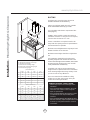
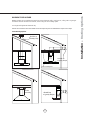
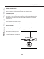
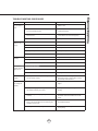
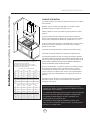
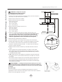
Installation – Mounting Height & Clearance
6
www.zephyronline.com
DUCTING
A minimum of 6” round duct must be used to
PDLQWDLQPD[LPXPDLUÀRZHI¿FLHQF\
Always use rigid type metal ducts only. Flexible
GXFWVFRXOGUHVWULFWDLUÀRZE\XSWR
Use calculation worksheet to compute total duct
ZRUN3DJH
ALWAYS, when possible, reduce the number of
transitions and turns. If a long duct run is required,
increase duct size from 6” to 7” or 8”.
If turns or transitions are required: Install as far
away from duct opening and as far apart between
the two transitions as possible.
Minimum mount height between range top to hood
bottom should be no less than 26”.
Maximum mount height should be no higher than
34”.
It is important to install the hood at the proper
mounting height. Hoods mounted too low could
UHVXOWLQKHDWGDPDJHDQG¿UHKD]DUGZKLOHKRRGV
mounted too high will be hard to reach and will
ORRVHSHUIRUPDQFHDQGHI¿FLHQF\
If available, also refer to range manufacturer’s
height clearance requirements and recommended
hood mounting height above range. Always check
your local codes for any differences.
Duct cover extension kit available for ceiling
heights up to 12 feet. Turn to page 22 for part
number and ordering information.
DAMAGE-SHIPMENT / INSTALLATION:
3OHDVHIXOO\LQVSHFWXQLWIRUGDPDJHEHIRUH
installation.
,IWKHXQLWLVGDPDJHGLQVKLSPHQWUHWXUQWKH
unit to the store in which it was bought for
repair or replacement.
,IWKHXQLWLVGDPDJHGE\WKHFXVWRPHUUHSDLU
or replacement is the responsibility of the
customer.
,IWKHXQLWLVGDPDJHGE\WKHLQVWDOOHULIRWKHU
WKDQWKHFXVWRPHUUHSDLURIUHSODFHPHQWPXVW
be made by arrangement between customer
and installer.
26” min.
34” max.
min. A
min. B
max. C
min. D
min. E
max. F
36”
A
B
C
D
E
F
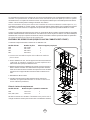
ZAN ZSA ZRV ZRO
Standard Duct Cover
Extension Duct Cover
A
B
C
D
E
F
ZAN ZSA ZRV ZRO
41”
45”
77”
103” (8’ 7”)
107” (8’ 11”)
147” (12’ 3”)
23”
27-
1/2”
42-
1/2”
85” (7’ 1”)
89-1/2” (7’ 5-1/2”)
112-
1/2” (9’ 4-1/2”)
41”
46”
80”
103” (8’ 7”)
108” (9’)
150” (12’ 6”)
28”
32”
45”
90” (7’ 6”)
94” (7’ 10”)
115” (9’ 7”)
46”
50”
80”
150” (12’ 6”)
110” (9’ 2”)
112” (9’ 4”)
27”
31”
48”
89” (7’ 5”)
93” (7’ 9”)
118” (9’ 10”)
43”
47”
81”
105” (8’ 9”)
109” (9’ 1”)
151” (12’ 7”)
A : Minimum Ducted Hood Height
B : Minimum Recirculating Hood Height
C : Maximum Hood Height
D : Minimum Ducted Ceiling Height
E : Minimum Recirculating Ceiling Height
F : Maximum Ceiling Height
26-1/2”
30-
1/2”
47-
1/2”
88-1/2” (7’ 4-1/2”)
92-
1/2” (7’ 8-1/2”)
117-
1/2” (9’ 9-1/2”)

7
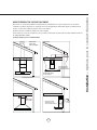
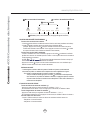
WARNING FIRE HAZARD
NEVER exhaust air or terminate duct work into spaces between walls, crawl spaces, ceiling, attics or garages.
All exhaust must be ducted to the outside, unless using the recirculating option.
Use single wall rigid metal ductwork only.
)DVWHQDOOFRQQHFWLRQVZLWKVKHHWPHWDOVFUHZVDQGWDSHDOOMRLQWVZFHUWL¿HG6LOYHU7DSHRU'XFW7DSH
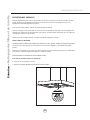
Some Ducting Options
Installation – Ducting Options
Roof Pitch w/
Flashing & Cap
side wall cap
w/ gravity damper
Soffit or crawl space
(blower
housing)
ductless
recirculating
side wall cap
w/ gravity damper
(blower
housing)

8
www.zephyronline.com
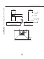
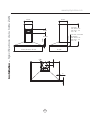
Installation – +RRG6SHFL¿FDWLRQ=$1
10 3/8”
1 3/16”
23 7/8”, 29 15/16”, 35 7/16”
10
5/8”
22
1/16”
5 5/16”
4"
1"
1"
6
"
STANDARD
min. ducted - 27”
min. recirc. - 31”
max. - 48”
Z1C-00AN, Z1C-00ANBS
EXTENSIONS
min. ducted - 43”
min. recirc. - 47”
max. - 81”
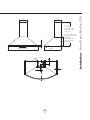
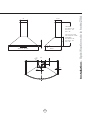
18 7/16”
6 5/16”

9
4"
6
"
CL
1”
9”
1”
29 15/16”, 35 7/16”
7
1/2”
19
1/2”
11”
STANDARD
min. ducted - 28”
min. recirc. - 32”
max. - 45”
Z1C-01SA, Z1C-01SAB
Z1C-01SAW, Z1C-01SABS
EXTENSIONS
min. ducted - 46”
min. recirc. - 50”
max. - 80”
1/2”
Installation – +RRG6SHFL¿FDWLRQ=6$

10
www.zephyronline.com
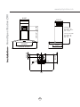
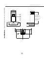
Installation – +RRG6SHFL¿FDWLRQ=59
STANDARD
min. ducted - 23”
min. recirc. - 27 1/2”
max. - 42 1/2”
Z1C-00RV, Z1C-00RVBS
min. ducted - 41”
min. recirc. - 46”
max. - 80”
10 9/16”
19 3/4”
10 3/8”
23 15/16”
15 5/16”
29 15/16, 35 3/16”
AC In
3 15/16”
6”
9 1/2”
C/L
6 1/4”
13 3/4”

11
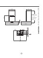
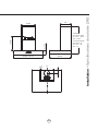
Installation – +RRG6SHFL¿FDWLRQ=52
CL
29
15/16”, 35 7/16”
14 1/8”
3”
22 1/16”
STANDARD
min. ducted - 26 1/2”
min. recirc. - 30 1/2”
max. - 47 1/2”
Z1C-00RO EXTENSION
min. ducted - 41”
min. recirc. - 45”
max. - 77”
11”
10 5/8”
6”
2 3/8”
2 5/8”
3 9/16”
5 5/8”

12
www.zephyronline.com
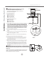
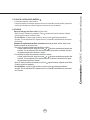
1. Measure from range top to hood bottom and mark line A.
´PLQLPXPIURPUDQJHWRS
2. Plum and mark center line.
3. Mark hood height line B.
ZAN : 18-7/16” from line A
ZSA : 9-1/2” from line A
ZRV : 15-7/8” from line A
ZRO : 12-3/16 from line A
4. Mark mounting spread from C/L.
ZAN : 8-7/8” on line B
ZSA : 9-7/8” on line B
ZRV : 8-15/16” on line B
ZRO : 12-5/8” on line B
)DVWHQ0[´VFUHZVLQWRVWXGVRQOLQH%EXWGRQRWWLJKWHQDOO
the way. Note: Wood blocking may need to be added behind the
drywall if no studs are present. Wall anchors may also be used
but check local codes for compliance. Failure to use suitable wall
anchors and screws to hold the weight of the hood could result
in personal injury or damage to the cooking surface or counter.
5HPRYHWKHDOXPLQXPPHVK¿OWHUV
7. Hang hood onto the mounting screws and hand tighten each screw.
)LJ$
8. Center and attach duct cover mounting bracket to wall just below the
FHLOLQJRUVRI¿WXVLQJ0[´VFUHZV
9. Install electrical and duct work. Seal duct work with aluminum duct
tape.
10. Power up hood and check for leaks around duct tape.
3ODFHWHOHVFRSLFGXFWFRYHUVRQWRKRRGDQGH[WHQGLQQHUWRSGXFW
FRYHUXSZDUGVDQGVHFXUHWRGXFWFRYHUEUDFNHWXVLQJ0[
VFUHZV5HLQVWDOOPHVK¿OWHUV
12. ZRV : Lilft glass canopy and place on top of hood body, secure glass
FDQRS\WRKRRGERG\E\[VFUHZV+DQGWLJKWHQVFUHZV
* If using hood in recirculating mode you must secure the air diverter
plate onto wall before installing duct work and duct covers. You will
DOVRQHHGWRLQVWDOOFKDUFRDO¿OWHUVDQGEUDFNHWV7XUQWRSDJHIRU
more details.
26” min.
CAUTION: At least two installers are required
due to the weight and size of the hood.
!
WARNING: Electrical wiring must be done by a qualified person(s) in
accordance with all applicable codes and standards. This range hood must be
properly grounded. Turn off electrical power at service entrance before wiring.
!
Cable Lock
Cable Lock
$FDEOHORFNLQJFRQQHFWRUQRWVXSSOLHGPLJKWEHUHTXLUHGE\ORFDO
codes. Check with local requirements and codes, purchase and
install appropriate connector if necessary.
Installation – Mounting the Hood
FIG. A

13
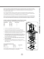
Ductless recirculation is intended for applications where an exhaust duct work is not possible to be installed.
When converted, the hood functions as a recirculating hood rather than an exhaust hood. Fumes and exhaust
IURPFRRNLQJDUHGUDZQDQG¿OWHUHGE\DVHWRIRSWLRQDOFKDUFRDO¿OWHUV7KHDLULVWKHQSXUL¿HGDQGUH
circulated back within the home.
We recommend to ALWAYS exhaust air outside of the home by employing existing or installing new duct
ZRUNLISRVVLEOH7KHKRRGLVPRVWHIIHFWLYHDQGHI¿FLHQWDVDQH[KDXVWKRRG2QO\ZKHQWKHH[KDXVWRSWLRQ
is not possible should you recourse to converting the hood into a recirculating hood.
:KHQFRQYHUWHGWREHDUHFLUFXODWLQJKRRGDVHWRIFKDUFRDO¿OWHUVDUHUHTXLUHGRQWRSRILWVVWDQGDUG0HWDO
)LOWHUVHW2UGHUDFFRUGLQJWRLWVSDUWQXPEHUEHORZ7KHVWDQGDUGPHVK¿OWHUVDUHLQWHQGHGWRFDSWXUHUHVLGXH
IURPFRRNLQJDQGWKHRSWLRQDOFKDUFRDO¿OWHUVKHOSWRSXULI\IXPHVH[KDXVWHGIURPFRRNLQJIRUUHFLUFXODWLRQ
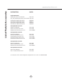
RECIRCULATING KIT (REQUIRED IF NO DUCTING IS USED)
.LWLQFOXGHVFKDUFRDO¿OWHUVFKDUFRDO¿OWHUEUDFNHWVDQGDLUGLYHUWHUSODWH
Hood Models Part No. Filters in pkg.
ZAN ZRC-01AN 2
ZSA ZRC-00SV 2
ZRV ZRC-00RV 2
ZRO ZRC-01RO 2
1. Purchase recirculating kit per the part number above
2. Secure air diverter plate to wall below duct cover bracket. Run 6”
GXFWLQJIURPWRSRIKRRGDQGVHFXUHWRDLUGLYHUWHUSODWH),*%
=$15HPRYHDOXPLQXPPHVK¿OWHUVIURPKRRG6HFXUHFKDUFRDO¿OWHUV
WREDFNVLGHRIDOXPLQXPPHVK¿OWHUE\EUDFNHWV),*%
=6$=59=525HPRYHDOXPLQXPPHVK¿OWHUVIURPKRRG6HFXUH
FKDUFRDO¿OWHUEUDFNHWVWRWKHKRRGERG\EHKLQGHDFKPHVK¿OWHUVXVLQJ
WKHVFUHZVLQFOXGHGLQWKHUHFLUFXODWLQJNLW&OLSFKDUFRDO¿OWHUVRQWR
HDFKFKDUFRDO¿OWHUEUDFNHW),*%
5H,QVWDOOPHVK¿OWHUVFor more details refer to manual included
with recirculating kit.
&KDUFRDO¿OWHUVPXVWEHUHSODFHGDIWHUHYHU\KRXUVRIXVHRU
approximately every 3 to 4 months based on an average of 1 - 2 hrs. of
GDLO\FRRNLQJWLPH
Charcoal Filter Replacements
Hood Model Part No. Qty to Order
ZAN Z0F-C091 2
ZSA / ZRV / ZRO Z0F-C002 2
'2127:$6+&+$5&2$/),/7(56&KDUFRDO¿OWHUVPD\QHHG
to be changed more often depending on cooking habits.
Installation – Ductless Recirculating
B.1
B.2
FIG. B

14
www.zephyronline.com
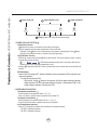
Lights On/Dim/Off
Display (speed level, delay off, filter clean/change)
Adjust 5 Speed Levels
Power / Delay Off
1 POWER / DELAY OFF BUTTON
Power Button Function
- Button will turn power on and off for entire hood (fan and lights).
- Hood will remember the last speed and light level it was turned off at.
(Example: Press Button to turn off hood when on fan speed 4 and high lights. Press Button
again and the hood will turn back on at speed 4 and high lights level.)
Delay Off Button Function
- With the fan on press and hold the Button for two seconds. The fan will change to speed 1 and the
5 minute delay off timer will start.
+ LEDs will illuminate and slowly blink in accordance with the time
remaining until the fan and lights automatically turn off.
- Pressing Button while Delay Off Function is enabled will turn the hood off and cancel the Delay Off
Function.
ACT Verification
- Airflow Control Technology (ACT) allows the installer to set the maximum fan CFM to align with local
codes and regulations.
- To verify the maximum fan CFM:
- With hood off, hold the Button for two seconds. If all five fan speed indicators illuminate =
default maximum CFM. If four fan speed indicators illuminate = 390 maximum CFM. If 3 fan
speed indicators illuminate = 290 maximum CFM.
2 SPEED SELECTION BUTTON
Fan Speed Decrease Button
- Press this button to decrease fan speed. 5, 4, 3, 2, 1.
- If fan is On Speed 1 and this button is pressed, fan will power Off.
Fan Speed Increase Button
- Press this button to increase fan speed. Fan On, 1, 2, 3, 4, 5.
- If hood is Off and this button is pressed, fan will turn On Speed 1.
Act Enabled Speed Selections
- When ACT is enabled, the number of fan speeds will be reduced as follows:
- 390 CFM = Maximum 4 speeds
- 290 CFM = Maximum 3 speeds
Features & Controls - ICON Touch Controls

15
3 LIGHTS BUTTON
- Lights are two levels, High and Low.
- From off, press one time for High. Press again for Low. Press again to power lights off.
4 DISPLAY INDICATORS
Mesh Filter Clean Reminder (always enabled)
- After 30 hours of fan usage, the button indicator will begin to slowly blink indicating it is time to
clean the mesh filters.
- To reset: With hood off: hold the button for three seconds. All LED indicators will blink two times
confirming the 30 hour timer has been reset.
Charcoal Filter Replace Indicator (disabled by default, must be enabled if recirculating hood)
- To enable Charcoal Filter Replacement Reminder:
- With hood off, hold button and button simultaneously for two seconds. All LED indicators
will illuminate for three seconds confirming the Charcoal Filter Replace Reminder is enabled.
- To disable Charcoal Filter Replacement Reminder:
- With hood off, hold button and button simultaneously for two seconds. All LED indicators
will blink two times confirming the Charcoal Filter Replace Reminder is disabled.
- After 120 hours of fan usage the button will slowly blink indicating the charcoal filters need
replacment.
- To reset: With hood off, hold the button for two seconds. All LED indicators will blink two times
confirming the 120 hour timer has been reset.
Features & Controls - ICON Touch Controls

16
www.zephyronline.com
SURFACE MAINTENANCE:
Do not use corrosive detergents, abrasive detergents or oven cleaners.
Do not use any product containing chlorine bleach or any product containing chloride.
Do not use steel wool or abrasive scrubbing pads which will scratch and damage surface.
Cleaning Stainless Steel
&OHDQSHULRGLFDOO\ZLWKZDUPVRDS\ZDWHUDQGFOHDQFRWWRQFORWKRUPLFUR¿EHUFORWK$OZD\VUXELQWKH
direction of the stainless steel grain. To remove heavier grease build up use a liquid degreaser detergent.
After cleaning use a non-abrasive stainless steel polish/cleaners, to polish and buff out the stainless luster
DQGJUDLQ$OZD\VVFUXEOLJKWO\ZLWKFOHDQFRWWRQFORWKRUPLFUR¿EHUFORWKDQGEXIILQWKHGLUHFWLRQRIWKH
stainless steel grain.
Cleaning Black Stainless Steel
&OHDQSHULRGLFDOO\ZLWKZDUPVRDS\ZDWHUDQGFOHDQFRWWRQFORWKRUPLFUR¿EHUFORWK7RUHPRYHKHDYLHU
grease build up use a liquid degreaser detergent.
Due to a built-in layer of protective anti-smudge coating, do not use stainless steel polish/cleaners to buff
out black stainless steel.
Aluminum Mesh Filters
7KHDOXPLQXPPHVK¿OWHUVLQVWDOOHGE\WKHIDFWRU\DUHLQWHQGHGWR¿OWHURXWUHVLGXHDQGJUHDVHIURP
cooking. They need not be replaced on a regular basis but are required to be kept clean.
Remove and clean by hand or in dishwasher on low heat. Spray degreasing detergent and leave to soak if
heavily soiled.
'U\¿OWHUVDQGUHLQVWDOOEHIRUHXVLQJKRRG
Removing Aluminum Mesh Filters
3XOOGRZQRQ¿OWHUODWFKWRUHOHDVH¿OWHUWDEV
3XOOGRZQRQIURQWRI¿OWHUWRUHPRYH
Maintenance – Hood and Filter Cleaning

17
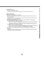
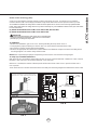
ALUÀRZ&RQWURO7HFKQRORJ\$&7
Some local codes limit the maximum amount of CFM a range hood can move. ACT allows you to control the
maximum blower CFM of select Zephyr Ventilation range hoods without the need for expensive make up air kits.
$&7HQDEOHVWKHLQVWDOOHUWRHDVLO\VHWWKHPD[LPXPEORZHUVSHHGWRRQHRIWZRPRVWFRPPRQO\VSHFL¿HG&)0
OHYHOVRU&)07KHXVDJHRI$&7PD\QRWEHQHFHVVDU\IRU\RXULQVWDOODWLRQ3OHDVHFKHFN\RXUORFDOFRGHV
for CFM restrictions.
By default the maximum blower CFM is set to 600 for ZAN, ZRV and ZRO.
By default the maximum blower CFM is set to 685 for ZSA.
To enable ACT
1. Before hood installation, gain access to PC board by following the steps shown in FIG. C.
2. Change plastic jumper positioning as shown in FIG. D to set the desired maximum blower CFM.
3. Re-install PC board & continue with hood installation.
4. Remove the appropriate foil CFM sticker included with the hood literature and place inside the hood body below
the wiring diagram or in another clearly visible location.
NOTE: After re-positioning the jumper and powering on the hood, the CFM cannot be changed again.
To verify if your installer enabled ACT
With hood off, press and hold the power button for three seconds. If 5 LEDs illuminate = defualt max. CFM, if 4 LEDs
illuminate = max. 390 CFM, and if 3 LEDs illuminate = max. 290 CFM.
When ACT is enabled, the number of blower speeds will be reduced. 390 CFM = max. 4 speeds and 290 CFM =
max. 3 speeds.
There should also be a foil label located inside the hood body near the wiring diagram that indicates the blower CFM.
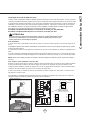
ACT Conversion
CAUTION:
Hood must be disconnected from main power prior to performing the
conversion instructions listed below. Failure to do so could result in
personal injury or damage to the product.
!
PC Board
1
3
5
7
2
4
6
8
Jumper 5-6 or 7-8
DEFAULT POSITION
Default Max. Blower CFM
Jumper 3-4
Max. Blower CFM
390
Jumper 1-2
Jumper Pins
Plastic
Jumper
1
3
5
7
2
4
6
8
1
3
5
7
2
4
6
8
1
3
5
7
2
4
6
8
Max. Blower CFM
290
FIG. C
FIG. D
Models: ZAN, ZRO, ZRV
- Locate PC board box on top of blower housing.
- Remove 2 to 4 screws attaching PC board cover.
Models: ZSA
- Remove aluminum mesh filters.
- Remove 2 to 4 screws attaching PC board cover.

18
www.zephyronline.com
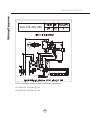
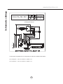
Wiring Diagrams
ZAN, ZSA, ZRV, ZRO
ACT 390 CFM - Fan Max. @ 2.3A
ACT 290 CFM - Fan Max. @ 1.9A
3RZHUFRQVXPSWLRQVKRZQIRUGHIDXOW&)0EORZHUFRQ¿JXUDWLRQ
La page est en cours de chargement...
La page est en cours de chargement...
La page est en cours de chargement...
La page est en cours de chargement...
La page est en cours de chargement...
La page est en cours de chargement...
La page est en cours de chargement...
La page est en cours de chargement...
La page est en cours de chargement...
La page est en cours de chargement...
La page est en cours de chargement...
La page est en cours de chargement...
La page est en cours de chargement...
La page est en cours de chargement...
La page est en cours de chargement...
La page est en cours de chargement...
La page est en cours de chargement...
La page est en cours de chargement...
La page est en cours de chargement...
La page est en cours de chargement...
La page est en cours de chargement...
La page est en cours de chargement...
La page est en cours de chargement...
La page est en cours de chargement...
La page est en cours de chargement...
La page est en cours de chargement...
La page est en cours de chargement...
La page est en cours de chargement...
La page est en cours de chargement...
La page est en cours de chargement...
La page est en cours de chargement...
La page est en cours de chargement...
-
 1
1
-
 2
2
-
 3
3
-
 4
4
-
 5
5
-
 6
6
-
 7
7
-
 8
8
-
 9
9
-
 10
10
-
 11
11
-
 12
12
-
 13
13
-
 14
14
-
 15
15
-
 16
16
-
 17
17
-
 18
18
-
 19
19
-
 20
20
-
 21
21
-
 22
22
-
 23
23
-
 24
24
-
 25
25
-
 26
26
-
 27
27
-
 28
28
-
 29
29
-
 30
30
-
 31
31
-
 32
32
-
 33
33
-
 34
34
-
 35
35
-
 36
36
-
 37
37
-
 38
38
-
 39
39
-
 40
40
-
 41
41
-
 42
42
-
 43
43
-
 44
44
-
 45
45
-
 46
46
-
 47
47
-
 48
48
-
 49
49
-
 50
50
-
 51
51
-
 52
52


Zephyr ZRO-E30DS Hood User Manual
- Catégorie
- Hottes
- Taper
- Hood User Manual
- Ce manuel convient également à
dans d''autres langues
- English: Zephyr ZRO-E30DS
Documents connexes
-
Zephyr ZSA-E30CW Manuel utilisateur
-
-
-
-
-
-
-
-
-
Essentials ZSA-E30CW Le manuel du propriétaire