Lincoln Electric IDEALARC R3R 600-I Manuel utilisateur
- Catégorie
- Système de soudage
- Taper
- Manuel utilisateur
Ce manuel convient également à

IDEALARC
®
R3R600-I
Operator’s Manual
Save for future reference
Date Purchased
Code: (ex: 10859)
Serial: (ex: U1060512345)
IM885-A | Issue D ate 6-Nov
© Lincoln Global, Inc. All Rights Reserved.
For use with machines having Code Numbers:
11289, 11343
Register your machine:
www.lincolnelectric.com/register
Authorized Service and Distributor Locator:
www.lincolnelectric.com/locator

i
SAFETY
i
FOR ENGINE
powered equipment.
1.a. Turn the engine off before troubleshooting and maintenance
work unless the maintenance work requires it to be running.
____________________________________________________
1.b.Operate engines in open, well-ventilated
areas or vent the engine exhaust fumes
outdoors.
____________________________________________________
1.c. Do not add the fuel near an open flame weld-
ing arc or when the engine is running. Stop
the engine and allow it to cool before refuel-
ing to prevent spilled fuel from vaporizing on
contact with hot engine parts and igniting. Do
not spill fuel when filling tank. If fuel is spilled,
wipe it up and do not start engine until fumes
have been eliminated.
____________________________________________________
1.d. Keep all equipment safety guards, covers
and devices in position and in good
repair.Keep hands, hair, clothing and tools
away from V-belts, gears, fans and all other
moving parts when starting, operating or
repairing equipment.
____________________________________________________
1.e. In some cases it may be necessary to remove safety
guards to perform required maintenance. Remove
guards only when necessary and replace them when the
maintenance requiring their removal is complete.
Always use the greatest care when working near moving
parts.
___________________________________________________
1.f. Do not put your hands near the engine fan. Do not attempt to
override the governor or idler by pushing on the throttle con-
trol rods while the engine is running.
___________________________________________________
1.g. To prevent accidentally starting gasoline engines while
turning the engine or welding generator during maintenance
work, disconnect the spark plug wires, distributor cap or
magneto wire as appropriate.
ARC WELDING CAN BE HAZARDOUS. PROTECT YOURSELF AND OTHERS FROM POSSIBLE SERIOUS INJURY OR DEATH.
KEEP CHILDREN AWAY. PACEMAKER WEARERS SHOULD CONSULT WITH THEIR DOCTOR BEFORE OPERATING.
Read and understand the following safety highlights. For additional safety information, it is strongly recommended that you
purchase a copy of “Safety in Welding & Cutting - ANSI Standard Z49.1” from the American Welding Society, P.O. Box 351040,
Miami, Florida 33135 or CSA Standard W117.2-1974. A Free copy of “Arc Welding Safety” booklet E205 is available from the
Lincoln Electric Company, 22801 St. Clair Avenue, Cleveland, Ohio 44117-1199.
BE SURE THAT ALL INSTALLATION, OPERATION, MAINTENANCE AND REPAIR PROCEDURES ARE
PERFORMED ONLY BY QUALIFIED INDIVIDUALS.
WARNING
Mar ‘95
ELECTRIC AND
MAGNETIC FIELDS
may be dangerous
2.a. Electric current flowing through any conductor causes
localized Electric and Magnetic Fields (EMF). Welding
current creates EMF fields around welding cables and
welding machines
2.b. EMF fields may interfere with some pacemakers, and
welders having a pacemaker should consult their physician
before welding.
2.c. Exposure to EMF fields in welding may have other health
effects which are now not known.
2.d. All welders should use the following procedures in order to
minimize exposure to EMF fields from the welding circuit:
2.d.1.
Route the electrode and work cables together - Secure
them with tape when possible.
2.d.2. Never coil the electrode lead around your body.
2.d.3. Do not place your body between the electrode and
work cables. If the electrode cable is on your right
side, the work cable should also be on your right side.
2.d.4. Connect the work cable to the workpiece as close as
possible to the area being welded.
2.d.5. Do not work next to welding power source.
1.h. To avoid scalding, do not remove the
radiator pressure cap when the engine is
hot.
CALIFORNIA PROPOSITION 65 WARNINGS
Diesel engine exhaust and some of its constituents
are known to the State of California to cause can-
cer, birth defects, and other reproductive harm.
The engine exhaust from this product contains
chemicals known to the State of California to cause
cancer, birth defects, or other reproductive harm.
The Above For Diesel Engines
The Above For Gasoline Engines

ii
SAFETY
ii
ARC RAYS can burn.
4.a. Use a shield with the proper filter and cover
plates to protect your eyes from sparks and
the rays of the arc when welding or observing
open arc welding. Headshield and filter lens
should conform to ANSI Z87. I standards.
4.b. Use suitable clothing made from durable flame-resistant
material to protect your skin and that of your helpers from
the arc rays.
4.c. Protect other nearby personnel with suitable, non-flammable
screening and/or warn them not to watch the arc nor expose
themselves to the arc rays or to hot spatter or metal.
ELECTRIC SHOCK can kill.
3.a. The electrode and work (or ground) circuits
are electrically “hot” when the welder is on.
Do not touch these “hot” parts with your bare
skin or wet clothing. Wear dry, hole-free
gloves to insulate hands.
3.b. Insulate yourself from work and ground using dry insulation.
Make certain the insulation is large enough to cover your full
area of physical contact with work and ground.
In addition to the normal safety precautions, if welding
must be performed under electrically hazardous
conditions (in damp locations or while wearing wet
clothing; on metal structures such as floors, gratings or
scaffolds; when in cramped positions such as sitting,
kneeling or lying, if there is a high risk of unavoidable or
accidental contact with the workpiece or ground) use
the following equipment:
• Semiautomatic DC Constant Voltage (Wire) Welder.
• DC Manual (Stick) Welder.
• AC Welder with Reduced Voltage Control.
3.c. In semiautomatic or automatic wire welding, the electrode,
electrode reel, welding head, nozzle or semiautomatic
welding gun are also electrically “hot”.
3.d. Always be sure the work cable makes a good electrical
connection with the metal being welded. The connection
should be as close as possible to the area being welded.
3.e. Ground the work or metal to be welded to a good electrical
(earth) ground.
3.f.
Maintain the electrode holder, work clamp, welding cable and
welding machine in good, safe operating condition. Replace
damaged insulation.
3.g. Never dip the electrode in water for cooling.
3.h. Never simultaneously touch electrically “hot” parts of
electrode holders connected to two welders because voltage
between the two can be the total of the open circuit voltage
of both welders.
3.i. When working above floor level, use a safety belt to protect
yourself from a fall should you get a shock.
3.j. Also see Items 6.c. and 8.
FUMES AND GASES
can be dangerous.
5.a. Welding may produce fumes and gases
hazardous to health. Avoid breathing these
fumes and gases.When welding, keep
your head out of the fume. Use enough
ventilation and/or exhaust at the arc to keep
fumes and gases away from the breathing zone. When
welding with electrodes which require special
ventilation such as stainless or hard facing (see
instructions on container or MSDS) or on lead or
cadmium plated steel and other metals or coatings
which produce highly toxic fumes, keep exposure as
low as possible and below Threshold Limit Values (TLV)
using local exhaust or mechanical ventilation. In
confined spaces or in some circumstances, outdoors, a
respirator may be required. Additional precautions are
also required when welding on galvanized steel.
5. b. The operation of welding fume control equipment is affected
by various factors including proper use and positioning of the
equipment, maintenance of the equipment and the specific
welding procedure and application involved. Worker expo-
sure level should be checked upon installation and periodi-
cally thereafter to be certain it is within applicable OSHA PEL
and ACGIH TLV limits.
5.c.
Do not weld in locations near chlorinated hydrocarbon
vapors
coming from degreasing, cleaning or spraying operations.
The heat and rays of the arc can react with solvent vapors
to
form phosgene, a highly toxic gas, and other irritating prod-
ucts.
5.d. Shielding gases used for arc welding can displace air and
cause injury or death. Always use enough ventilation,
especially in confined areas, to insure breathing air is safe.
5.e. Read and understand the manufacturer’s instructions for this
equipment and the consumables to be used, including the
material safety data sheet (MSDS) and follow your
employer’s safety practices. MSDS forms are available from
your welding distributor or from the manufacturer.
5.f. Also see item 1.b.
AUG 06

iii
SAFETY
iii
FOR ELECTRICALLY
powered equipment.
8.a. Turn off input power using the disconnect
switch at the fuse box before working on
the equipment.
8.b. Install equipment in accordance with the U.S. National
Electrical Code, all local codes and the manufacturer’s
recommendations.
8.c. Ground the equipment in accordance with the U.S. National
Electrical Code and the manufacturer’s recommendations.
CYLINDER may explode
if damaged.
7.a. Use only compressed gas cylinders
containing the correct shielding gas for the
process used and properly operating
regulators designed for the gas and
pressure used. All hoses, fittings, etc. should be suitable for
the application and maintained in good condition.
7.b. Always keep cylinders in an upright position securely
chained to an undercarriage or fixed support.
7.c. Cylinders should be located:
• Away from areas where they may be struck or subjected to
physical damage.
• A safe distance from arc welding or cutting operations and
any other source of heat, sparks, or flame.
7.d. Never allow the electrode, electrode holder or any other
electrically “hot” parts to touch a cylinder.
7.e. Keep your head and face away from the cylinder valve outlet
when opening the cylinder valve.
7.f. Valve protection caps should always be in place and hand
tight except when the cylinder is in use or connected for
use.
7.g. Read and follow the instructions on compressed gas
cylinders, associated equipment, and CGA publication P-l,
“Precautions for Safe Handling of Compressed Gases in
Cylinders,” available from the Compressed Gas Association
1235 Jefferson Davis Highway, Arlington, VA 22202.
Mar ‘95
WELDING SPARKS can
cause fire or explosion.
6.a.
Remove fire hazards from the welding area.
If this is not possible, cover them to prevent
the welding sparks from starting a fire.
Remember that welding sparks and hot
materials from welding can easily go through small cracks
and openings to adjacent areas. Avoid welding near
hydraulic lines. Have a fire extinguisher readily available.
6.b. Where compressed gases are to be used at the job site,
special precautions should be used to prevent hazardous
situations. Refer to “Safety in Welding and Cutting” (ANSI
Standard Z49.1) and the operating information for the
equipment being used.
6.c. When not welding, make certain no part of the electrode
circuit is touching the work or ground. Accidental contact can
cause overheating and create a fire hazard.
6.d. Do not heat, cut or weld tanks, drums or containers until the
proper steps have been taken to insure that such procedures
will not cause flammable or toxic vapors from substances
inside. They can cause an explosion even
though
they have
been “cleaned”. For information, purchase “Recommended
Safe Practices for the
Preparation
for Welding and Cutting of
Containers and Piping That Have Held Hazardous
Substances”, AWS F4.1 from the American Welding Society
(see address above).
6.e. Vent hollow castings or containers before heating, cutting or
welding. They may explode.
6.f.
Sparks and spatter are thrown from the welding arc. Wear oil
free protective garments such as leather gloves, heavy shirt,
cuffless trousers, high shoes and a cap over your hair. Wear
ear plugs when welding out of position or in confined places.
Always wear safety glasses with side shields when in a
welding area.
6.g. Connect the work cable to the work as close to the welding
area as practical. Work cables connected to the building
framework or other locations away from the welding area
increase the possibility of the welding current passing
through lifting chains, crane cables or other alternate circuits.
This can create fire hazards or overheat lifting chains or
cables until they fail.
6.h. Also see item 1.c.

iv
SAFETY
iv
Mar. ‘93
PRÉCAUTIONS DE SÛRETÉ
Pour votre propre protection lire et observer toutes les instructions
et les précautions de sûreté specifiques qui parraissent dans ce
manuel aussi bien que les précautions de sûreté générales suiv-
antes:
Sûreté Pour Soudage A L’Arc
1. Protegez-vous contre la secousse électrique:
a. Les circuits à l’électrode et à la piéce sont sous tension
quand la machine à souder est en marche. Eviter toujours
tout contact entre les parties sous tension et la peau nue
ou les vétements mouillés. Porter des gants secs et sans
trous pour isoler les mains.
b. Faire trés attention de bien s’isoler de la masse quand on
soude dans des endroits humides, ou sur un plancher met-
allique ou des grilles metalliques, principalement dans
les positions assis ou couché pour lesquelles une grande
partie du corps peut être en contact avec la masse.
c. Maintenir le porte-électrode, la pince de masse, le câble de
soudage et la machine à souder en bon et sûr état defonc-
tionnement.
d.Ne jamais plonger le porte-électrode dans l’eau pour le
refroidir.
e. Ne jamais toucher simultanément les parties sous tension
des porte-électrodes connectés à deux machines à souder
parce que la tension entre les deux pinces peut être le total
de la tension à vide des deux machines.
f. Si on utilise la machine à souder comme une source de
courant pour soudage semi-automatique, ces precautions
pour le porte-électrode s’applicuent aussi au pistolet de
soudage.
2. Dans le cas de travail au dessus du niveau du sol, se protéger
contre les chutes dans le cas ou on recoit un choc. Ne jamais
enrouler le câble-électrode autour de n’importe quelle partie du
corps.
3. Un coup d’arc peut être plus sévère qu’un coup de soliel, donc:
a. Utiliser un bon masque avec un verre filtrant approprié ainsi
qu’un verre blanc afin de se protéger les yeux du rayon-
nement de l’arc et des projections quand on soude ou
quand on regarde l’arc.
b. Porter des vêtements convenables afin de protéger la peau
de soudeur et des aides contre le rayonnement de l‘arc.
c. Protéger l’autre personnel travaillant à proximité au
soudage à l’aide d’écrans appropriés et non-inflammables.
4. Des gouttes de laitier en fusion sont émises de l’arc de
soudage. Se protéger avec des vêtements de protection libres
de l’huile, tels que les gants en cuir, chemise épaisse, pan-
talons sans revers, et chaussures montantes.
5. Toujours porter des lunettes de sécurité dans la zone de
soudage. Utiliser des lunettes avec écrans lateraux dans les
zones où l’on pique le laitier.
6. Eloigner les matériaux inflammables ou les recouvrir afin de
prévenir tout risque d’incendie dû aux étincelles.
7. Quand on ne soude pas, poser la pince à une endroit isolé de
la masse. Un court-circuit accidental peut provoquer un
échauffement et un risque d’incendie.
8. S’assurer que la masse est connectée le plus prés possible de
la zone de travail qu’il est pratique de le faire. Si on place la
masse sur la charpente de la construction ou d’autres endroits
éloignés de la zone de travail, on augmente le risque de voir
passer le courant de soudage par les chaines de levage,
câbles de grue, ou autres circuits. Cela peut provoquer des
risques d’incendie ou d’echauffement des chaines et des
câbles jusqu’à ce qu’ils se rompent.
9. Assurer une ventilation suffisante dans la zone de soudage.
Ceci est particuliérement important pour le soudage de tôles
galvanisées plombées, ou cadmiées ou tout autre métal qui
produit des fumeés toxiques.
10. Ne pas souder en présence de vapeurs de chlore provenant
d’opérations de dégraissage, nettoyage ou pistolage. La
chaleur ou les rayons de l’arc peuvent réagir avec les vapeurs
du solvant pour produire du phosgéne (gas fortement toxique)
ou autres produits irritants.
11. Pour obtenir de plus amples renseignements sur la sûreté, voir
le code “Code for safety in welding and cutting” CSA Standard
W 117.2-1974.
PRÉCAUTIONS DE SÛRETÉ POUR
LES MACHINES À SOUDER À
TRANSFORMATEUR ET À
REDRESSEUR
1. Relier à la terre le chassis du poste conformement au code de
l’électricité et aux recommendations du fabricant. Le dispositif
de montage ou la piece à souder doit être branché à une
bonne mise à la terre.
2. Autant que possible, I’installation et l’entretien du poste seront
effectués par un électricien qualifié.
3. Avant de faires des travaux à l’interieur de poste, la debranch-
er à l’interrupteur à la boite de fusibles.
4. Garder tous les couvercles et dispositifs de sûreté à leur place.

vv
Thank You
for selecting a QUALITY product by Lincoln Electric. We want you
to take pride in operating this Lincoln Electric Company product •••
as much pride as we have in bringing this product to you!
Read this Operators Manual completely before attempting to use this equipment. Save this manual and keep it
handy for quick reference. Pay particular attention to the safety instructions we have provided for your protection.
The level of seriousness to be applied to each is explained below:
WARNING
This statement appears where the information must be followed exactly to avoid serious personal injury or
loss of life.
This statement appears where the information must be followed to avoid minor personal injury or damage to
this equipment.
CAUTION
Please Examine Carton and Equipment For Damage Immediately
When this equipment is shipped, title passes to the purchaser upon receipt by the carrier. Consequently, Claims
for material damaged in shipment must be made by the purchaser against the transportation company at the time
the shipment is received.
Please record your equipment identification information below for future reference. This information can be found
on your machine nameplate.
Product _________________________________________________________________________________
Model Number ___________________________________________________________________________
Code Number or Date Code_________________________________________________________________
Serial Number____________________________________________________________________________
Date Purchased___________________________________________________________________________
Where Purchased_________________________________________________________________________
Whenever you request replacement parts or information on this equipment, always supply the information you
have recorded above. The code number is especially important when identifying the correct replacement parts.
On-Line
Product Registration
- Register your machine with Lincoln Electric either via fax or over the Internet.
• For faxing: Complete the form on the back of the warranty statement included in the literature packet
accompanying this machine and fax the form per the instructions printed on it.
• For On-Line Registration: Go to our
WEB SITE at www.lincolnelectric.com. Choose “Quick Links” and then
“Product Registration”. Please complete the form and submit your registration.

vi
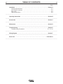
TABLE OF CONTENTS
vi
Page
Installation . . . . . . . . . . . . . . . . . . . . . . . . . . . . . . . . . . . . . . . . . . . . . . . . . . . . . . . . . Section A
Technical Specifications . . . . . . . . . . . . . . . . . . . . . . . . . . . . . . . . . . . . . . . . . . . . . . . . . .A-1
Input Power Connection . . . . . . . . . . . . . . . . . . . . . . . . . . . . . . . . . . . . . . . . . . . . . . . . . A-2
Duty Cycle . . . . . . . . . . . . . . . . . . . . . . . . . . . . . . . . . . . . . . . . . . . . . . . . . . . . . . . . . . . . A-2
Output Connections . . . . . . . . . . . . . . . . . . . . . . . . . . . . . . . . . . . . . . . . . . . . . . . . . . . . . A-2
__________________________________________________________________________________________
Operating Instructions . . . . . . . . . . . . . . . . . . . . . . . . . . . . . . . . . . . . . . . . . . . . . . . Section B
__________________________________________________________________________________________
Accessories . . . . . . . . . . . . . . . . . . . . . . . . . . . . . . . . . . . . . . . . . . . . . . . . . . . . . . . . Section C
__________________________________________________________________________________________
Maintenance . . . . . . . . . . . . . . . . . . . . . . . . . . . . . . . . . . . . . . . . . . . . . . . . . . . . . . . . Section D
__________________________________________________________________________________________
Troubleshooting . . . . . . . . . . . . . . . . . . . . . . . . . . . . . . . . . . . . . . . . . . . . . . . . . . . . . Section E
Troubleshooting Procedures . . . . . . . . . . . . . . . . . . . . . . . . . . . . . . . . . . . . . . . . E-7 – E-10
__________________________________________________________________________________________
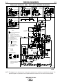
Wiring Diagram . . . . . . . . . . . . . . . . . . . . . . . . . . . . . . . . . . . . . . . . . . . . . . . . . . . . . . Section F
__________________________________________________________________________________________
Parts Lists . . . . . . . . . . . . . . . . . . . . . . . . . . . . . . . . . . . . . . . . . . . . . . . . . . . . . . . P-527 Series
__________________________________________________________________________________________

A-1
INSTALLATION
IDEALARC R3R 600-I
A-1
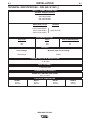
TECHNICAL SPECIFICATIONS – R3R 600-I K1381-[ ]
Volts at Rated Amperes
35
40
44
Amps
375
500
600
Duty Cycle
100%
60%
35%
INPUT - THREE PHASE ONLY
OUTPUT
Insulation Class: 155°C (F)
Standard Voltage Frequency
220-230V/50/60Hz
380-400V/50/60Hz
440-460V/50/60Hz
11.3@220V/50Hz
.74 @ 500A
Rated Input Current
103A @ 600A Output
92A @ 500A Output
68A @ 375A Output
(220V/50/60Hz)
(V
olts/Hz)
DC RATED OUTPUT
PHYSICAL DIMENSIONS
HEIGHT
27.5 in
699 mm
WIDTH
22.3 in
566 mm
DEPTH
32.0 in
813 mm
WEIGHT
446 lbs.
203 kg.
Current Range
75-625 Amps
}
Maximum Open Circuit Voltage
64VDC
TEMPERATURE RANGES
POWER FACTOR @ RATED LOAD
IDLE CURRENT
OPERATING TEMPERATURE RANGE
-40°C to +40°C

A-2
INSTALLATION
IDEALARC R3R 600-I
A-2
INSTALLATION
FALLING EQUIPMENT can cause
injury.
• Do not lift this machine using lift
bail if it is equipped with a heavy
• accessory such as trailer or gas cylinder.
• Lift only with equipment of adequate lifting
capacity.
• Be sure machine is stable when lifting.
The machine should be located in a clean, dry place
where there is free circulation of clean air, such that air
movement entering the front and exiting the back will
not be restricted. Dirt and dust that can be drawn into
the machine should be kept to a minimum. Failure to
observe these precautions can result in excessive
operating temperatures and nuisance shutdown of the
machine.
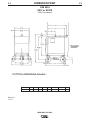
The Idealarc R3R welders can be stacked three high
when the following precautions are observed:
1. Be sure the bottom machine is on a firm, level sur-
face suitable for the total weight [up to 1340 pounds
(608 kg)] of the stacked machines.
2. Stack the machines with the fronts flush. Be certain
the pins on the top front corners of the lower
machines fit through the holes in the base rails of
the upper machines.
3. No unit heavier than the bottom unit should be
stacked on top of it. For example, an R3R 500-I
shall not be slacked on top of an R3R 400-I, but an
R3R 400-I may be stacked on top of an R3R 500-I.
INPUT POWER CONNECTION
ELECTRIC SHOCK can kill.
• Have an electrician install and ser-
vice this equipment.
• Turn the input power off at the fuse
box before working on equipment.
• Do not touch electrically hot parts.
Remove the rear access panel. Connect the three
phase input power to the three line terminals on the
input contactor, and the earth ground lead to the
ground stud marked with the symbol. Install the
reconnect panel for the proper input voltage per the
diagram pasted inside the access panel cover.
DUTY CYCLE
The maximum output rating of this welder is at a 35%
duty cycle. Duty cycle is based on a ten minute period.
Therefore, the welder can be operated at the maximum
rated output for 3.5 minutes out of every 10 minute
period without overheating.
Failure to follow these instructions can cause immedi-
ate failure of components within the machine.
When powering welder from a generator be sure to
turn off welder first, before generator is shut down,
in order to prevent damage to welder!
------------------------------------------------------------------------
OUTPUT CONNECTIONS
With the machine power switch off, the output leads
are connected to the Magnum™ Twist-Mate™ output
terminals marked “–” and “+”. They are located at the
lower right and lower left corners of the front panel.
Strain relief for the electrode and work cables is pro-
vided by routing the leads through the rectangular
holes in the base before the connections to the output
terminals are made. Twist-Mate Lead plugs must be
installed to the output cables before connections can
be made to the power source. See S18737 instructions
included with the plugs.
The recommended output cable sizes can be found in
the Table below.
WARNING
WARNING
Copper Wire Size
Input
Type 75°C in Conduit
Super Lag
R3R Volts Amps 3 Input 1 Ground Fuse Size
Welder 50/60 Hz Input Wires Wire in Amps
220 - 230 103 4 6 150
600-I 380 - 400 60 8 8 90
440 - 460 52 8 8 70
Machine Up to 100 ft. 100 to 150 ft. 150 to 200 ft. 200 to 250 ft.
Size (30 m) (30 – 46 m) (46 – 61 m) (61 – 76 m)
600-I 2/0 (68 mm
2
) 3/0 (86 mm
2
) 3/0 (86 mm
2
) 4/0 (108 mm
2
)
CAUTION

B-1
OPERATION
B-1
OPERATION
ELECTRIC SHOCK can kill.
• Do not touch electrically live parts
or electrode with skin or wet cloth-
ing.
• Insulate yourself from work and ground.
• Always wear dry insulating gloves.
FUMES AND GASES can be danger-
ous.
• Keep your head out of fumes.
• Use ventilation or exhaust to
• remove fumes from breathing zone.
WELDING SPARKS can cause fire or
explosion.
• Keep flammable material away.
• Do not weld on containers that
have held combustibles.
ARC RAYS can burn.
• Wear eye, ear and body protection.
STARTING THE MACHINE
The “power on-off” switch on the machine control panel
energizes the three phase line contactor from a small
115 volt pilot transformer. This in turn energizes the
main power transformer.
NOTE: All PC boards are protected by a moisture
resistant coating. When the welder is operated, this
coating will “bake off” of certain power resistors that
normally operate at high temperatures, emitting some
smoke and odor for a short time. These resistors and
the PC board beneath them may become blackened.
This is a normal occurrence and does not damage the
component or affect the machine performance.
PILOT LIGHT
The while light on the machine control panel indicates
when The line contactor is energized.
NOTE: If the amber High Temperature Warning Light is
lit, it indicates that one or both of the protective ther-
mostats has opened the line contactor.
OUTPUT CONTROL
The “current control” dial (labeled “I”) on the front of the
machine indicates the output current.
On the R3R 375-I, there is only one dial. On the R3R
500-I, and 600-I, there are two dials. The “A” range
controls the current over about 1/2 of the “B” range. A
toggle switch on the control panel allows selection of
the desired range. The output control can be adjusted
while welding.
MACHINE OR REMOTE CURRENT
CONTROL SWITCH
Provisions for remote control are standard on each
power source. A current control switch on the machine
control panel labeled “ “or “ I “ is provided for
selecting the desired mode of operation, either remote
( )or at the machine ( I ).
ARC FORCE CONTROL
The arc force control, located on the right side of the
front control panel, is calibrated from one to ten. For
most welding, the dial should be set at approximately
mid-range, 5-6. Adjustments up or down can then be
made depending on the electrode, procedures, and
operator preference. Lower settings will provide less
short circuit current and a softer arc. A setting that is
too low may cause the electrode to stick in the puddle.
Higher settings will provide a higher short circuit cur-
rent and a more forceful arc. Excessive spatter may
result if the control setting is too high. For most TIG
welding applications, adjust this control to minimum for
best operating characteristics.
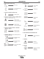
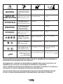
INTERNATIONAL SYMBOLOGY
REFERENCE
The R3R name plates feature international symbols in
describing the function of the various components.
Below are the symbols used and an explanation of
what each represents.
A. POWER ON-OFF SWITCH
On
Off
Power Input
IDEALARC R3R 600-I
WARNING

B-2
OPERATION
B-2
B. ARC FORCE CONTROL DIAL
Arc Force
Increase/Decrease of
Arc Force
C. OUTPUT CURRENT CONTROL DIAL
Output Current
D. OUTPUT CURRENT CONTROL RANGE SWITCH
(R3R 500-I and R3R 600-I only)
Output Current
Control Dial Range A
Output Current
Control Dial Range B
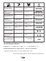
E. OUTPUT CURRENT CONTROL “MACHINE-
REMOTE” SWITCH
Remote Output
Current Control
F. POLARITY SWITCH (Factory installed option on
domestic models only)
Electrode Polarity
Positive
Electrode Polarity
Negative
Do Not Switch While
Welding
G. RATING PLATE
Three Phase
Power
Transformer
Rectifier
Rectified DC
Output
Constant Current
Characteristics
Shielded Metal Arc
Welding
Line Connection
H. HIGH TEMPERATURE WARNING LIGHT
High Temperature
Limit
I. WARNING
Warning
Identification
J. GROUND
Signifying the Earth
(Ground)
Connection
IDEALARC R3R 600-I

C-1
ACCESSORIES
C-1
OPTIONAL EQUIPMENT
K857 – REMOTE CURRENT CONTROL
The K857 consists of a control box with 8.5 m (28 ft) of
four conductor cable and a 6 pin Amphenol for easy
connection to the front of the power source.
The K857 will give the same control as the current con-
trol on the machine depending on the position of the
current dial selector switch. (Current dial selector
switch not used on the R3R 375-I.)
Extreme care must be observed when installing or
extending the wiring of a remote control. The
Remote Control cord can be lengthened to any
length by splicing four wires to the standard 28 ft
(8.5 m) cord before connecting to the R3R recep-
tacle. Only the green lead can and should be
grounded to the machine case.
K841 – UNDERCARRIAGE
For easy moving of the machine, platform undercar-
riage with mounting two gas cylinders at the rear of
welder.
K963 – HAND AMPTROL AND K870 FOOT
AMPTROL
Connect directly to the 6 pin Amphenol on the front of
the power source.
AMMETER AND VOLTMETER – (factory installed
only)
IDEALARC R3R 600-I
CAUTION

D-1
MAINTENANCE
D-1
ELECTRIC SHOCK can kill.
• Have an electrician install and ser-
vice this equipment.
• Turn the input power off at the fuse
box before working on equipment.
• Do not touch electrically hot parts.
ROUTINE MAINTENANCE
1. The fan motor has sealed bearings which require no
service.
2. In extremely dusty locations, dirt may clog the air
channels causing the welder to run hot. Blow out
the machine at regular intervals.
POCKET AMPTROL
Routine cleaning should be the only maintenance
required. The probe tip should be kept in condition to
provide sharp edges at the ends to assure penetration
of heavy oxide coatings on the work piece. A blunted
tip could result in giving different welding currents for a
given dial setting.
POWER RECTIFIER REPLACEMENT
Refer to the troubleshooting section “Power Rectifier
Bridge Assembly Checking Procedure” if a rectifier fail-
ure is suspected
NOTE: Since proper material and correct assembly
procedures are critical, field disassembly of the power
rectifier bridge sections can do more harm than good.
Return a defective rectifier bridge section (or the entire
bridge) to the factory for repairs.
IDEALARC R3R 600-I
WARNING

E-1
TROUBLESHOOTING
E-1
IDEALARC R3R 600-I
If for any reason you do not understand the test procedures or are unable to perform the tests/repairs safely, contact your Local
Lincoln Authorized Field Service Facility for technical troubleshooting assistance before you proceed.
CAUTION
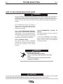
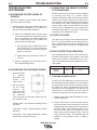
This Troubleshooting Guide is provided to
help you locate and repair possible machine
malfunctions. Simply follow the three-step
procedure listed below.
Step 1. LOCATE PROBLEM (SYMPTOM).
Look under the column labeled “PROBLEM
(SYMPTOMS)”. This column describes pos-
sible symptoms that the machine may exhib-
it. Find the listing that best describes the
symptom that the machine is exhibiting.
Step 2. POSSIBLE CAUSE.
The second column labeled “POSSIBLE
CAUSE” lists the obvious external possibili-
ties that may contribute to the machine
symptom.
Step 3. RECOMMENDED COURSE OF
ACTION
This column provides a course of action for
the Possible Cause.
If you do not understand or are unable to
perform the Recommended Course of Action
safely, contact you local Lincoln Authorized
Field Service Facility.
HOW TO USE TROUBLESHOOTING GUIDE
Service and Repair should only be performed by Lincoln Electric Factory Trained Personnel.
Unauthorized repairs performed on this equipment may result in danger to the technician
and machine operator and will invalidate your factory warranty. For your safety and to avoid
Electrical Shock, please observe all safety notes and precautions detailed throughout this
manual.
__________________________________________________________________________
WARNING
WARNING
ELECTRIC SHOCK can kill.
• Do not touch electrically hot parts.
• Have an electrician install and service this equip-
ment.
• Turn the input power off at the fuse box before
working on equipment.

E-2
TROUBLESHOOTING
E-2
IDEALARC R3R 600-I
Observe all Safety Guidelines detailed throughout this manual
If for any reason you do not understand the test procedures or are unable to perform the tests/repairs safely, contact your Local
Lincoln Authorized Field Service Facility for technical troubleshooting assistance before you proceed.
CAUTION
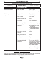
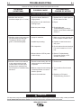
FUNCTION PROBLEMS
PROBLEMS
(SYMPTOMS)
POSSIBLE CAUSE
RECOMMENDED
COURSE OF ACTION
A. Input contactor chatters.
B. Machine input contactor does not
operate.
1.Faulty input contactor.
2.Low line voltage.
1.Supply line fuse blown.
2.Power circuit dead.
3.Broken or loose power lead.
4.Wrong voltage.
5.Thermostats tripped. (High
Temperature Warning Light
should be lit.) (Welder
overheated.)
6.Input contactor coil open.
7.Open winding on 115V pilot
transformer.
8.Power ON-OFF switch not
closing.
9.Lead broken or loose connec-
tion in 115V starter circuit.
10.Thermostats defective. (High
Temperature Warning Light
should be lit.)
1.Repair or replace.
2.Check with Power Company.
1.Replace (look for reason for
blown fuse first).
2.Check voltage.
3.Repair.
4.Check voltage against
instructions.
5.a. Make sure the fan is operating
and that there are no obstruc-
tions to free flow of air.
b. Operate at normal current
and duty cycle.
c. Replace High Temperature
Warning Light if defective.
6.Replace.
7.Replace.
8.Replace.
9.Replace.
10.Turn input power off (115V cir-
cuit is hot when input power is
connected). Check thermostats
with continuity meter – should
read short-circuit when machine
is cool. Replace if defective.
There are two thermostats; one
on the secondary lead and one
on the choke. Replace High
Temperature Warning Light if
defective.

E-3
TROUBLESHOOTING
E-3
IDEALARC R3R 600-I
Observe all Safety Guidelines detailed throughout this manual
If for any reason you do not understand the test procedures or are unable to perform the tests/repairs safely, contact your Local
Lincoln Authorized Field Service Facility for technical troubleshooting assistance before you proceed.
CAUTION
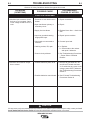
FUNCTION PROBLEMS
PROBLEMS
(SYMPTOMS)
POSSIBLE CAUSE
RECOMMENDED
COURSE OF ACTION
C. Machine input contactor closes
but has no or low output. Open
circuit voltage should be 67 to 71
volts.
D. Machine has maximum output
but no control.
1. Electrode or work lead loose or
broken.
2. Open transformer primary or
secondary circuit.
3. Supply line fuse blown.
4. Input line grounded causing
single phase input.
5. Input leads not connected to
contactor.
6. Latching resistor, R3, open.
7. Control circuit problems.
1. Possible defective power SCR.
2. Possible defective control board.
1. Repair connections.
2. Repair.
3. Replace blown fuse – check fuse
size.
4. Repair input to machine.
5. Connect input lead.
6. a. Replace.
b. Check leads to the resistor
and repair if defective.
7. See Troubleshooting Procedures
– Power Silicon Controlled
Rectifier.
1. Remove all gate leads G1, G2
and G3 at PC board connector
J4. If welder has any open circuit
voltage, power SCR is defective.
See Troubleshooting Procedures
Section J.
2. See PC board Troubleshooting
Procedures Section A

E-4
TROUBLESHOOTING
E-4
IDEALARC R3R 600-I
Observe all Safety Guidelines detailed throughout this manual
If for any reason you do not understand the test procedures or are unable to perform the tests/repairs safely, contact your Local
Lincoln Authorized Field Service Facility for technical troubleshooting assistance before you proceed.
CAUTION
FUNCTION PROBLEMS
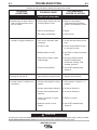
PROBLEMS
(SYMPTOMS)
POSSIBLE CAUSE
RECOMMENDED
COURSE OF ACTION
E. Machine does not have
maximum output (67 to 71 volts).
F. Machine comes on but soon trips
off while under load and High
Temperature Warning Light
glows. (Thermostat tripped)
G.Machine comes on but reduces
to low output under load and
remains there until the load is
broken and arc restarted. See
Fault Protection Troubleshooting
Section E.
1. Input fuse blown. Machine is
single phased.
2. One phase of main transformer
windings open.
3. Defective power bridge.
1. Improper ventilation.
2. Loaded beyond rating.
3. Fan inoperative.
4. Shorted diode or SCR in power
rectifier bridge.
1. Excessive load causing the over-
load protection on control board
to operate.
2. Machine output shorted causing
overload protection on control
board to operate.
3. Control circuit defective.
1. Replace fuse or repair input line.
Check reason for fault.
2. Repair.
3. Check bridge per
Troubleshooting Procedures
Section J and check snubber per
Section F.
1. Make sure all case openings are
free for proper circulation of air.
2. Operate at rated current and
duty cycle.
3. Check leads and motor bearings.
Fan can be tested on 115 volt
line.
4. Refer to Troubleshooting
Procedures Section J and
Snubber, Section F.
1. Reduce load.
2. Turn machine off and remove
short.
3. Replace per PC board,
Troubleshooting, Section A.

E-5
TROUBLESHOOTING
E-5
IDEALARC R3R 600-I
Observe all Safety Guidelines detailed throughout this manual
If for any reason you do not understand the test procedures or are unable to perform the tests/repairs safely, contact your Local
Lincoln Authorized Field Service Facility for technical troubleshooting assistance before you proceed.
CAUTION
FUNCTION PROBLEMS
PROBLEMS
(SYMPTOMS)
POSSIBLE CAUSE
RECOMMENDED
COURSE OF ACTION
H. Machine trips off when under no
load or makes excessive noise
like it is loaded.
I. Variable or sluggish welding arc.
J. Welder will not shut off.
K. Current control on machine not
functioning.
1. Power bridge rectifier may have
a shorted diode or SCR.
2. Short in the transformer.
3. Fan hitting vertical baffle.
1. Poor work or electrode cable
connection.
2. Current too low.
3. Welding leads too small.
4. Open SCR or diode in power
rectifier bridge.
5. Control circuit problems.
1. Input contactor contacts frozen.
1. Current control switch in wrong
position.
2. Current control switch defective.
3. Current control potentiometer
defective.
4. Lead or connection in control
circuit open.
5. Defective control or circuit
boards.
1. Refer to Power Hybrid,
Troubleshooting Procedures,
Section J and Snubber, Section
F.
2. Repair.
3. Clear the fan.
1. Check and clean cable connec-
tions.
2. Check recommended currents
for rod type and size.
3. See Table in Output Connection
Section.
4. Check per Power Rectifier
Bridge Troubleshooting
Procedures, Section J and
Snubber, Section F.
5. See SCR Troubleshooting,
Section K.
1. Replace input contactor.
1. Place switch in “machine” ( I )
position.
2. Check per Section H.
3. Check per Section G.
4. Repair or connect.
5. See SCR Troubleshooting,
Section K.

E-6
TROUBLESHOOTING
E-6
IDEALARC R3R 600-I
Observe all Safety Guidelines detailed throughout this manual
If for any reason you do not understand the test procedures or are unable to perform the tests/repairs safely, contact your Local
Lincoln Authorized Field Service Facility for technical troubleshooting assistance before you proceed.
CAUTION
FUNCTION PROBLEMS
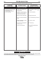
PROBLEMS
(SYMPTOMS)
POSSIBLE CAUSE
RECOMMENDED
COURSE OF ACTION
L. Optional remote current control
not functioning. See
Troubleshooting , Section C
before connecting.
1. Current control switch in the
wrong position.
2. Leads 75, 76 and 77 not con-
nected to correct numbers on
models with terminal strip.
3. Remote control leads broken.
4. Remote control potentiometer
open.
5. Lead or connection in current
control circuit open.
6. Control PC board plug discon-
nected or loose.
7. Control circuit problems.
1. Place switch in “remote” ( )
position.
2. Correct connection.
3. Repair broken leads.
4. See Troubleshooting, Section C.
5. Connect or repair.
6. Connect plug.
7. See SCR Troubleshooting,
Section K.

E-7
TROUBLESHOOTING
E-7
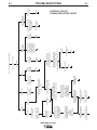
IDEALARC R3R 600-I
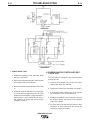
Low output, low OCV, or erratic welding
Turn control dial to minimum
Check OCV
OCV is 35-55V OCV is 40-45V OCV is 0 Rated OCV but OCV less than rated
erratic welding but more than 55V
OCV 45-55V OCV 35-45V Possible machine Check leads 76, 77, Possible Loose lead Possible intermittent Possible Possible wrong connection Possible defective
is being 212, 213, 210, 211 defective connections or loose connections defective of gate leads if recent PC board
single phased & SW2 for open PC board on shunt in control circuit. PC board PC board or rectifier
Check aux. voltages Check PC board con- stack change.
on PC board nector, switches,
potentiometers, etc.
201-202 = 120V ± 10% Replace Retighten Replace See wiring diagram Replace
201-202 = 120V ± 10% leads and correct
202-203 = 120V ± 10% Remove and replace Gate leads
G-1, G-2, G-3 from PC board
one at a time.
If aux. voltages
are incorrect, If aux. voltages If removing each gate lead If removing and replacing
check & repair. are OK one at a time changes OCV each gate lead one at a
time does NOT change OCV
Codes below 9500
with power off, remove leads from Identify gate lead that, when
Codes above 9500 75, 76, 77 terminal strip and removed, OCV did not change.
with power off, disconnect welding leads from output terminals Remove gate lead. Voltage
remote control amphenol between gate lead and 204 must be 13-17V.
and welding leads from
output terminals.
Check resistance of each If voltage OK If voltage is
terminal on this terminal not correct
strip to ground. Resistance
Check the following pins must be as follows: Defective power SCR
for resistance to ground. 75-GND 2K minimum Possible defective
Resistance must be as 76-GND 2K minimum PC board
follows: 77-GND 12K minimum Replace
GND 2K min.
GND 2K min. Replace.
GND 12K min.
If not, clear terminal strip If resistance is OK,
and leads, and also check possible defective
SW2 and R1 for dirt. PC board.
If not, examine amphenol If resistance is OK, possible
assembly for faults. defective PC board.
If fault found, repair or If amphenol OK, possible
replace amphenol assembly. defective PC board.
CONTROL CIRCUIT
TROUBLESHOOTING CHART
La page est en cours de chargement...
La page est en cours de chargement...
La page est en cours de chargement...
La page est en cours de chargement...
La page est en cours de chargement...
La page est en cours de chargement...
La page est en cours de chargement...
La page est en cours de chargement...
-
 1
1
-
 2
2
-
 3
3
-
 4
4
-
 5
5
-
 6
6
-
 7
7
-
 8
8
-
 9
9
-
 10
10
-
 11
11
-
 12
12
-
 13
13
-
 14
14
-
 15
15
-
 16
16
-
 17
17
-
 18
18
-
 19
19
-
 20
20
-
 21
21
-
 22
22
-
 23
23
-
 24
24
-
 25
25
-
 26
26
-
 27
27
-
 28
28


Lincoln Electric IDEALARC R3R 600-I Manuel utilisateur
- Catégorie
- Système de soudage
- Taper
- Manuel utilisateur
- Ce manuel convient également à
dans d''autres langues
Documents connexes
-
Lincoln Electric Hi Freq Mode d'emploi
-
-
-
-
Lincoln Electric Idealarc R3R-400 Mode d'emploi
-
-
-
-
-