Indesit C 31 N1 (W) EX Mode d'emploi
- Catégorie
- Fours
- Taper
- Mode d'emploi

C 31 N1 EX
Contents
Installation, 2-5
Positioning and levelling
Electrical connection
Gas connection
Adapting to different types of gas
Technical data
Table of burner and nozzle specifications
Description of the appliance, 6
Overall view
Control panel
Start-up and use, 7-9
Using the hob
Using the oven
Practical advice on using the electric hotplates
Practical cooking advice
Oven cooking advice table
Precautions and tips, 10
General safety
Disposal
Respecting and conserving the environment
Care and maintenance, 11
Switching the appliance off
Cleaning the appliance
Gas tap maintenance
Replacing the oven light bulb
Assistance
Operating Instructions
COOKER
GB
English, 1 Français, 12
FRGB
AR

2
GB
Before operating your new appliance please read
this instruction booklet carefully. It contains
important information concerning the safe installation
and operation of the appliance.
Please keep these operating instructions for future
reference. Make sure that the instructions are kept
with the appliance if it is sold, given away or moved.
The appliance must be installed by a qualified
professional according to the instructions provided.
Any necessary adjustment or maintenance must be
performed after the cooker has been disconnected
from the electricity supply.
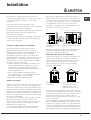
Room ventilation
The appliance may only be installed in permanently-
ventilated rooms, according to current national
legislation. The room in which the appliance is
installed must be ventilated adequately so as to
provide as much air as is needed by the normal gas
combustion process (the flow of air must not be
lower than 2 m
3
/h per kW of installed power).
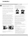
The air inlets, protected by grilles, should have a
duct with an inner cross section of at least 100 cm
2
and should be positioned so that they are not liable
to even partial obstruction (see figure A).
These inlets should be enlarged by 100% - with a
minimum of 200 cm
2
- whenever the surface of the
hob is not equipped with a flame failure safety
device. When the flow of air is provided in an
indirect manner from adjacent rooms (see figure B),
provided that these are not communal parts of a
building, areas with increased fire hazards or
bedrooms, the inlets should be fitted with a
ventilation duct leading outside as described above.
After prolonged use of the appliance, it is
advisable to open a window or increase the speed of
any fans used.
Disposing of combustion fumes
The disposal of combustion fumes should be
guaranteed using a hood connected to a safe and
efficient natural suction chimney, or using an electric
fan that begins to operate automatically every time
the appliance is switched on (see figure).
The liquefied petroleum gases are heavier than air
and collect by the floor, therefore all rooms
containing LPG cylinders must have openings
leading outside so that any leaked gas can escape
easily.
LPG cylinders, therefore, whether partially or
completely full, must not be installed or stored in
rooms or storage areas that are below ground level
(cellars, etc.). Only the cylinder being used should
be stored in the room; this should also be kept well
away from sources of heat (ovens, chimneys,
stoves) that may cause the temperature of the
cylinder to rise above 50°C.
Positioning and levelling
It is possible to install the appliance alongside
cupboards whose height does not exceed that of the
hob surface.
Make sure that the wall in contact with the back of
the appliance is made from a non-flammable, heat-
resistant material (T 90°C).
To install the appliance correctly:
Place it in the kitchen, the dining room or the bed-
sit (not in the bathroom).
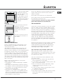
If the top of the hob is higher than the cupboards,
the appliance must be installed at least 200 mm
away from them.
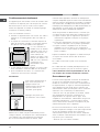
If the cooker is installed underneath a wall cabinet,
there must be a minimum distance of 420 mm
between this cabinet and the top of the hob.
This distance should be increased to 700 mm if the
wall cabinets are flammable (see figure).
A
Installation
Ventilation opening for
comburent air
Increase in the gap
between the door and
the flooring
Adjacent room
Room requiring
ventilation
A
B
Fumes channelled
straight outside
Fumes channelled through
a chimney or a branched
flue system (reserved for
cooking appliances)

3
GB
Do not position blinds
behind the cooker or
less than 200 mm away
from its sides.
Any hoods must be
installed according to
the instructions listed in
the relevant operating
manual.
Le velling
If it is necessary to level the
appliance, screw the
adjustable feet into the places
provided on each corner of the
base of the cooker (see
figure).
The legs* fit into the slots on
the underside of the base of
the cooker.
HOOD
420
Min.
min.
650
mm. with hood
min.
700
mm. without hood
mm.
600
Min. mm.
420
Min. mm.
* Only available in certain models.
Electrical connections
Install a standardised plug corresponding to the
load indicated on the appliance data plate (see
Technical data table).
The appliance must be directly connected to the
mains using an omnipolar circuit-breaker with a
minimum contact opening of 3 mm installed between
the appliance and the mains. The circuit-breaker
must be suitable for the charge indicated and must
comply with NFC 15-100 regulations (the earthing
wire must not be interrupted by the circuit-breaker).
The supply cable must be positioned so that it does
not come into contact with temperatures higher than
50°C at any point.
Before connecting the appliance to the power
supply, make sure that:
The appliance is earthed and the plug is compliant
with the law.
The socket can withstand the maximum power of
the appliance, which is indicated by the data plate.
The voltage is in the range between the values
indicated on the data plate.
The socket is compatible with the plug of the
appliance. If the socket is incompatible with the
plug, ask an authorised technician to replace it.
Do not use extension cords or multiple sockets.
Once the appliance has been installed, the power
supply cable and the electrical socket must be
easily accessible.
The cable must not be bent or compressed.
The cable must be checked regularly and replaced
by authorised technicians only.
The manufacturer declines any liability should
these safety measures not be observed.
Gas connection
Connection to the gas network or to the gas cylinder
may be carried out using a flexible rubber or steel
hose, in accordance with current national legislation
and after making sure that the appliance is suited to
the type of gas with which it will be supplied (see
the rating sticker on the cover: if this is not the case
see below). When using liquid gas from a cylinder,
install a pressure regulator which complies with
current national regulations. To make connection
easier, the gas supply may be turned sideways*:
reverse the position of the hose holder with that of
the cap and replace the gasket that is supplied with
the appliance.
Check that the pressure of the gas supply is consistent
with the values indicated in the Table of burner and
nozzle specifications (see below). This will ensure the
safe operation and durability of your appliance while
maintaining efficient energy consumption.
Gas connection using a flexible rubber hose
Make sure that the hose complies with current
national legislation. The internal diameter of the hose
must measure: 8 mm for liquid gas supply; 13 mm
for methane gas supply.
Once the connection has been performed, make
sure that the hose:
Does not come into contact with any parts that
reach temperatures of over 50°C.
Is not subject to any pulling or twisting forces and
that it is not kinked or bent.
Does not come into contact with blades, sharp
corners or moving parts and that it is not
compressed.
Is easy to inspect along its whole length so that
its condition may be checked.
Is shorter than 1500 mm.
Fits firmly into place at both ends, where it will be
fixed using clamps that comply with current
regulations.

4
GB
Connecting a flexible jointless stainless steel
pipe to a threaded attachment
Make sure that the hose and gaskets comply with
current national legislation.
To begin using the hose, remove the hose holder on
the appliance (the gas supply inlet on the appliance
is a cylindrical threaded 1/2 gas male attachment).
Perform the connection in such a way that the hose
length does not exceed a maximum of 2 metres,
making sure that the hose is not compressed and
does not come into contact with moving parts.
Checking the connection for leaks
When the installation process is complete, check
the hose fittings for leaks using a soapy solution.
Never use a flame.
Adapting to different types of gas
It is possible to adapt the appliance to a type of gas
other than the default type (this is indicated on the
rating label on the cover).
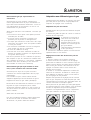
Adapting the hob
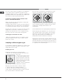
Replacing the nozzles for the hob burners:
1. Remove the hob grids and slide the burners off
their seats.
2. Unscrew the nozzles using
a 7 mm socket spanner (see
figure), and replace them with
nozzles suited to the new type
of gas (see Burner and nozzle
specifications table).
3. Replace all the components
by following the above instructions in reverse.
Adjusting the hob burners minimum setting:
1. Turn the tap to the minimum position.
2. Remove the knob and adjust the regulatory
screw, which is positioned inside or next to the tap
pin, until the flame is small but steady.
In the case of natural gas, the adjustment screw
must be unscrewed by turning it anti-clockwise.
3. While the burner is alight, quickly change the position
of the knob from minimum to maximum and vice versa
several times, checking that the flame is not
extinguished.
The hob burners do not require primary air adjustment.
After adjusting the appliance so it may be used
with a different type of gas, replace the old rating
label with a new one that corresponds to the new
type of gas (these labels are available from
Authorised Technical Assistance Centres).
Should the gas pressure used be different (or vary
slightly) from the recommended pressure, a suitable
pressure regulator must be fitted to the inlet hose in
accordance with current national regulations relating
to regulators for channelled gas.
If one or more of these conditions is not fulfilled or
if the cooker must be installed according to the
conditions listed for class 2 - subclass 1 appliances
(installed between two cupboards), the flexible steel
hose must be used instead (see below).

5
GB
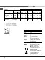
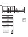
Table of burner and nozzle specifications
S
R
A
Ø180
C 34S N1 R
Table 1 Liquid Gas Natural Gas
Diameter
(mm)
Thermal Power
kW (p.c.s.*)
By Pass
1/100
Nozzle
1/100
Flow*
g/h
Nozzle
1/100
Flow*
l/h
Burner
Nominal Reduced (mm) (mm) *** ** (mm)
Fast
(Large)(R)
100 3.00 0.7 41 87 218 214 128 286
Semi Fast
(Medium)(S)
75 1.90 0.4 30 70 138 136 104 181
Auxiliary
(Small)(A)
51 1.00 0.4 30 52 73 71 76 95
Supply
Pressures
Nominal (mbar)
Minimum (mbar)
Maximum (mbar)
28-
30 20
35
37 2
545
20 17 25
* At 15°C 1013 mbar-dry gas *** Butane P.C.S. = 49,47 MJ/Kg
** Propane P.C.S. = 50,37 MJ/K
g
Natural P.C.S. = 37,78 MJ/m³
TECHNICAL DATA
Oven dimensions
(HxWxD)
34x39x44 cm
Volume
58 l
Useful
measurements
relating to the
oven
compartment
width 42 cm
depth 44 cm
height 17 cm
Power supply
voltage and
frequency
see data plate
Burners
may be adapted for use with any
type of gas shown on the data
plate, which is located inside the
flap or, after the oven compartment
has been opened, on the left-hand
wall inside the oven.
ENERGY LABEL
Directive 2002/40/EC on the label
of electric ovens. Standard EN
50304
Declared energy consumption for
Natural convection Class – heating
mode:
=
Static
EC Directives: 73/23/EEC dated
19/02/73 (Low Voltage) and
subsequent amendments -
89/336/EEC dated 03/05/89
(Electromagnetic Compatibility) and
subsequent amendments -
90/369/EEC dated 29/06/90 (Gas)
and subsequent amendments -
93/68/EEC dated 22/07/93 and
subsequent amendments -
2002/96/EC.

6
GB
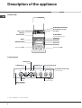
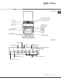
Description of the appliance
Control panel
Overall view
*
Only available in certain models.
TIMER
knob*
THERMOSTAT
knob
THERMOSTAT
indicator light
ACTIVE HOTPLATE
indicator light
Hob BURNER
control knobs
SELECTOR
Knob
GAS BURNER
ignition button*
ELECTRIC HOTPLATE
control knob
ELECTRIC HOTPLATE
Hob grid
Control panel
GRILL
DRIPPING PAN
GUIDE RAILS
for the sliding racks
position 3
position 2
position 1
Gas burner
Containment surface
for spills
Adjustable foot
Adjustable foot
position 5
position 4

7
GB
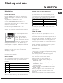
Using the hob
Lighting the burners
For each BURNER knob there is a complete ring
showing the strength of the flame for the relevant
burner.
To light one of the burners on the hob:
1. Bring a flame or gas lighter close to the burner.
2. Press the BURNER knob and turn it in an
anticlockwise direction so that it is pointing to the
maximum flame setting -.
3. Adjust the intensity of the flame to the desired
level by turning the BURNER knob in an
anticlockwise direction. This may be the minimum
setting +, the maximum setting - or any position in
between the two.
If the appliance is fitted with
an electronic lighting device*
(see figure), press the ignition
button, marked with the
symbol
, then hold the
BURNER knob down and turn
it in an anticlockwise direction,
towards the maximum flame
setting, until the burner is lit. The burner may be
extinguished when the knob is released. If this
occurs, repeat the operation, holding the knob down
for a longer period of time.
If the flame is accidentally extinguished, switch off
the burner and wait for at least 1 minute before
attempting to relight it.
To switch the burner off, turn the knob until it
reaches the stop position .
Electric hotplates
The corresponding knob may be turned clockwise or
anti-clockwise and set to any of the six different
positions:
Setting Normal or Fast Plate
0
Off
1
Low
2 - 5
Medium
6
High
When the selector knob is in any position other than
the off position, the on light is illuminated.
Start-up and use
Practical advice on using the burners
For the burners to work in the most efficient way
possible and to save on the amount of gas
consumed, it is recommended that only pans that
have a lid and a flat base are used. They should
also be suited to the size of the burner.
To identify the type of burner, please refer to the
diagrams contained in the Burner and nozzle
specifications.
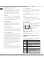
Using the oven
The first time you use your appliance, heat the
empty oven with its door closed at its maximum
temperature for at least half an hour. Ensure that the
room is well ventilated before switching the oven off
and opening the oven door. The appliance may emit
a slightly unpleasant odour caused by protective
substances used during the manufacturing process
burning away.
Before operating the product, remove all plastic
film from the sides of the appliance.
1. Select the desired cooking mode by turning the
SELECTOR knob.
2. Select the recommended temperature for the
cooking mode or the desired temperature by turning
the THERMOSTAT knob.
A list detailing cooking modes and suggested
cooking temperatures can be found in the relevant
table (see Oven cooking advice table).
During cooking it is always possible to:
Change the cooking mode by turning the
SELECTOR knob.
Change the temperature by turning the
THERMOSTAT knob.
Set the total cooking time and the cooking end
time (see below).
Stop cooking by turning the SELECTOR knob to
the 0 position.
Never put objects directly on the bottom of the
oven; this will avoid the enamel coating being
damaged.
Always place cookware on the rack(s) provided.
*
Only available in certain models.
Burner ø Cookware diameter (cm)
Fast (R) 24 - 26
Semi Fast (S) 16 - 20
Auxiliary (A) 10 - 14

8
GB
THERMOSTAT indicator light
When this is illuminated, the oven is generating
heat. It switches off when the inside of the oven
reaches the selected temperature. At this point the
light illuminates and switches off alternately,
indicating that the thermostat is working and is
maintaining the temperature at a constant level.
Oven light
This is switched on by turning the SELECTOR knob
to any position other than 0. It remains lit as long
as the oven is operating. By selecting
&
with the
knob, the light is switched on without any of the
heating elements being activated.
Cooking modes
A temperature value can be set for all cooking
modes between 50°C and MAX, except for the
GRILL programme, for which only the MAX power
level is recommended.
=
STATIC OVEN mode
Both the top and bottom heating elements will come
on. When using this traditional cooking mode, it is
best to use one cooking rack only. if more than one
rack is used, the heat will be distributed unevenly.
O
OVEN BOTTOM mode
The lower heating element is activated. This position
is recommended for perfecting the cooking of
dishes (in baking trays) which are already cooked on
the surface but require further cooking in the centre,
or for desserts with a covering of fruit or jam, which
only require moderate colouring on the surface. It
should be noted that this function does not allow the
maximum temperature to be reached inside the oven
(250°C) and it is therefore not recommended that
foods are cooked using only this setting, unless you
are baking cakes (which should be baked at a
temperature of 180°C or lower).
?
GRILL mode
The top heating element is activated. The extremely
high and direct temperature of the grill makes it
possible to brown the surface of meats and roasts
while locking in the juices to keep them tender.
@ DOUBLE GRILL mode
The top heating element is activated. The grill is also
highly recommended for dishes that require a high
surface temperature: beef steaks, veal, rib steak,
fillets, hamburgers etc...
The GRILL and DOUBLE GRILL cooking modes must
be performed with the oven door shut.
Timer*
To activate the Timer proceed as follows:
1. Turn the TIMER knob in a clockwise direction "
for almost one complete revolution to set the buzzer.
2. Turn the TIMER knob in an anticlockwise direction
# to set the desired length of time.
Lower compartment*
There is a compartment
underneath the oven
that may be used to
store oven accessories
or deep dishes. To open
the door pull it
downwards (see
figure).
Do not place flammable materials in the lower oven
compartment.
The internal surfaces of the compartment (where
present) may become hot.
Practical advice on using the electric
hotplates
To avoid heat loss and damage to the hotplates use
pans with a flat base, whose diameter is no less
than that of the hotplate itself.
Setting Normal or Fast Plate
0
Off
1
Cooking vegetables, fish
2
Cooking potatoes (using steam) soups,
chickpeas, beans.
3
Continuing the cooking of large quantities
of food, minestrone
4
For roasting (average)
5
For roasting (above average)
6
For browning and reaching a boil in a
short time.

9
GB
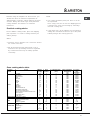
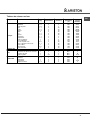
Oven cooking advice table
Cooking
modes
Foods Weight
(in kg)
Rack
position
Preheating time
(min)
Recommended
Temperature
(°C)
Cooking
time
(minutes)
Static
Lasagne
Cannelloni
Baked pasta
Veal
Chicken
Duck
Rabbit
Pork
Lamb
Mackerel
Mackerel
Trout baked in foil
Neapolitan-style pizza
Biscuits and small cakes
Sweet unleavened flans and desserts
Savoury pies
Leavened cakes
Fruit cakes
2.5
2.5
2.0
1.7
1.5
1.8
2
2.1
1.8
1.1
1.5
1
1
0.5
1.1
1
0.5
1
2
3
3
2
3
3
3
3
3
2
2
2
2
3
3
3
3
3
5
5
5
10
10
10
10
10
10
5
5
5
15
10
10
10
10
10
200
200
200
180
200
180
180
180
180
180
180
180
220
180
180
180
160
170
45-50
30-35
30-35
60-70
80-90
90-100
70-80
70-80
70-80
30-40
30-35
25-30
15-20
10-15
25-30
30-35
25-30
25-30
Oven bottom
Perfecting cooking
Grill
Sole and cuttlefish
Squid and prawn kebabs
Cod fillet
Grilled vegetables
1
1
1
1
4
4
4
3/4
5
5
5
5
Max
Max
Max
Max
8
4
10
8-10
Double Grill
Veal steak
Chops
Hamburgers
Mackerel
Toast
1
1.5
1
1
4 pcs
4
4
3
4
4
5
5
5
5
5
Max
Max
Max
Max
Max
15-20
20
7
15-20
5
Before using the hotplates for the first time, you
should heat them at maximum temperature for
approximately 4 minutes, without placing any pans
on them. During this initial stage, their protective
coating hardens and reaches its maximum
resistance.
Practical cooking advice
In the GRILL cooking mode, place the dripping
pan in position 1 to collect cooking residues (fat
and/or grease).
GRILL
Insert the rack in position 3 or 4. Place the food in
the centre of the rack.
We recommend that the power level is set to
maximum. The top heating element is regulated
by a thermostat and may not always operate
constantly.
PIZZA
Use a light aluminium pizza pan. Place it on the
rack provided.
For a crispy crust, do not use the dripping pan as
it prevents the crust from forming by extending
the total cooking time.
If the pizza has a lot of toppings, we recommend
adding the mozzarella cheese on top of the pizza
halfway through the cooking process.

10
GB
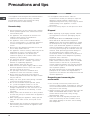
Precautions and tips
! The appliance was designed and manufactured in
compliance with international safety standards.
The following warnings are provided for safety
reasons and must be read carefully.
General safety
These instructions are only valid for the countries
whose symbols appear in the manual and on the
serial number plate.
The appliance was designed for domestic use
inside the home and is not intended for
commercial or industrial use.
The appliance must not be installed outdoors,
even in covered areas. It is extremely dangerous
to leave the appliance exposed to rain and
storms.
Do not touch the appliance with bare feet or with
wet or damp hands and feet.
The appliance must be used by adults only for the
preparation of food, in accordance with the
instructions provided in this booklet (the
instructions apply to all countries listed at the
beginning of the booklet).
The instruction booklet accompanies a class 1
(insulated) or class 2 - subclass 1 (recessed
between 2 cupboards) appliance.
Keep children away from the oven.
Make sure that the power supply cables of other
electrical appliances do not come into contact
with the hot parts of the oven.
The openings used for the ventilation and
dispersion of heat must never be covered.
Do not close the glass hob cover (selected
models only) when the burners are alight or when
they are still hot.
Always use oven gloves when placing cookware
in the oven or when removing it.
Do not use flammable liquids (alcohol, petrol,
etc...) near the appliance while it is in use.
Do not place flammable material in the lower
storage compartment or in the oven itself. If the
appliance is switched on accidentally, it could
catch fire.
Always make sure the knobs are in the position
and that the gas tap is closed when the appliance
is not in use.
When unplugging the appliance, always pull the
plug from the mains socket; do not pull on the
cable.
Never perform any cleaning or maintenance work
without having disconnected the appliance from
the electricity mains.
If the appliance breaks down, under no
circumstances should you attempt to repair the
appliance yourself. Repairs carried out by
inexperienced persons may cause injury or further
malfunctioning of the appliance. Contact
Assistance.
Do not rest heavy objects on the open oven door.
Disposal
When disposing of packaging material: observe
local legislation so that the packaging may be
reused.
The European Directive 2002/96/EC relating to
Waste Electrical and Electronic Equipment
(WEEE) states that household appliances should
not be disposed of using the normal solid urban
waste cycle. Exhausted appliances should be
collected separately in order to optimise the cost
of re-using and recycling the materials inside the
machine, while preventing potential damage to
the atmosphere and to public health. The
crossed-out dustbin is marked on all products to
remind the owner of their obligations regarding
separated waste collection.
Exhausted appliances may be collected by the
public waste collection service, taken to suitable
collection areas in the area or, if permitted by
current national legislation, they may be returned
to the dealers as part of an exchange deal for a
new equivalent product.
All major manufacturers of household appliances
participate in the creation and organisation of
systems for the collection and disposal of old and
disused appliances.
Respecting and conserving the
environment
You can help to reduce the peak load of the
electricity supply network companies by using the
oven in the hours between late afternoon and the
early hours of the morning.
Always keep the oven door closed when using the
GRILL and DOUBLE GRILL modes. This will
achieve better results while saving energy
(approximately 10%).
Check the door seals regularly and wipe them
clean to ensure they are free of debris so that
they adhere properly to the door, thus avoiding
heat dispersion.

11
GB
Switching the appliance off
Disconnect your appliance from the electricity
supply before carrying out any work on it.
Cleaning the appliance
Do not use abrasive or corrosive detergents such
as stain removers, anti-rust products, powder
detergents or sponges with abrasive surfaces: these
may scratch the surface beyond repair.
Never use steam cleaners or pressure cleaners on
the appliance.
It is usually sufficient simply to wash the hob
using a damp sponge and dry it with absorbent
kitchen roll.
The stainless steel or enamel-coated external
parts and the rubber seals may be cleaned using
a sponge that has been soaked in lukewarm water
and neutral soap. Use specialised products for
the removal of stubborn stains. After cleaning,
rinse well and dry thoroughly. Do not use abrasive
powders or corrosive substances.
The hob grids, burner caps, flame spreader rings
and burners may be removed to make cleaning
easier; wash them in hot water and non-abrasive
detergent, making sure all burnt-on residue is
removed before drying them thoroughly.
For hobs with electronic ignition, the terminal part
of the electronic lighting devices should be
cleaned frequently and the gas outlet holes
should be checked for blockages.
The inside of the oven should ideally be cleaned
after each use, while it is still lukewarm. Use hot
water and detergent, then rinse well and dry with
a soft cloth. Do not use abrasive products.
Clean the glass part of the oven door using a
sponge and a non-abrasive cleaning product,
then dry thoroughly with a soft cloth. Do not use
rough abrasive material or sharp metal scrapers
as these could scratch the surface and cause the
glass to crack.
The accessories can be washed like everyday
crockery, and are even dishwasher safe.
Stainless steel can be marked by hard water that
has been left on the surface for a long time, or by
aggressive detergents containing phosphorus.
After cleaning, rinse well and dry thoroughly. Any
remaining drops of water should also be dried.
Do not close the cover when the burners are alight
or when they are still hot.
Inspecting the oven seals
Check the door seals around the oven regularly. If
the seals are damaged, please contact your nearest
Authorised After-sales Service Centre. We
recommend that the oven is not used until the seals
have been replaced.
Gas tap maintenance
Over time, the taps may become jammed or difficult
to turn. If this occurs, the tap must be replaced.
This procedure must be performed by a qualified
technician authorised by the manufacturer.
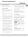
Replacing the oven light bulb
1. After disconnecting the
oven from the electricity
mains, remove the glass lid
covering the lamp socket (see
figure).
2. Remove the light bulb and
replace it with a similar one:
voltage 230 V, wattage 25 W,
cap E 14.
3. Replace the lid and reconnect the oven to the
electricity supply.
Assistance
Please have the following information to hand:
The appliance model (Mod.).
The serial number (S/N).
This information can be found on the data plate
located on the appliance and/or on the packaging.
Care and maintenance

C 31 N1 EX
Sommaire
Installation, 13-16
Positionnement et nivellement
Raccordement électrique
Raccordement gaz
Adaptation aux différents types de gaz
Données techniques
Tableau Caractéristiques des brûleurs et des
injecteurs
Description de lappareil, 17
Vue densemble
Tableau de bord
Mise en marche et utilisation, 18-21
Utilisation du plan de cuisson
Utilisation du four
Quelques conseils utiles pour bien utiliser votre
plaque électrique
Conseils de cuisson
Tableau de cuisson au four
Précautions et conseils, 22
Sécurité générale
Mise au rebut
Economies et respect de lenvironnement
Nettoyage et entretien, 23
Mise hors tension
Nettoyage de lappareil
Entretien robinets gaz
Remplacement de lampoule déclairage du four
Assistance
Mode demploi
CUISINIERE
FR
English, 1 Français, 12
GB FR
AR

13
FR
Conserver ce mode demploi pour pouvoir le
consulter tout moment. En cas de vente, de cession
ou de déménagement, veiller à ce quil suive
lappareil.
Lire attentivement les instructions : elles
contiennent des conseils importants sur linstallation,
lutilisation et la sécurité de lappareil
Linstallation de lappareil doit être effectuée par un
professionnel du secteur conformément aux
instructions du fabricant.
Nimporte quelle opération de réglage, dentretien
ou autre, doit être effectuée après avoir débranché
la prise de la cuisinière.
Conditions réglementaires dinstallation
Le raccordement gaz devra être fait par un
professionnel qualifié qui assurera la bonne
alimentation en gaz et le meilleur réglage de la
combustion des brûleurs. Ces opérations
dinstallation, quoique simples, sont délicates et
primordiales pour que votre cuisinière vous rende le
meilleur service. Linstallation doit être effectuée
conformément aux textes réglementaires et règles
de lart en vigueur, notamment:
Arrêté du 2 août 1977. Règles techniques et de
sécurité applicables aux installations de gaz
combustibles et dhydro-carbures liquéfiés
situées à lintérieur des bâtiments dhabitation et
de leur dépendances.
Norme DTU P45-204. Installations de gaz
(anciennement DTU n° 61-1-installations de gaz -
Avril 1982 + additif n°1 Juillet 1984).
Règlement sanitaire départemental.
Aération des locaux
Lappareil doit être installé dans des locaux qui sont
aérés en permanence, selon les prescriptions des
Normes en vigueur dans le pays dinstallation. Il est
indispensable que la pièce où lappareil est installé
dispose dune quantité dair égale à la quantité dair
comburant nécessaire à une bonne combustion du
gaz (le flux dair doit être dau moins 3 m
3
/h par kW
de puissance installée).
Les prises dair, protégées par des grilles, doivent
disposer dun conduit dau moins 100 cm
2
de
section utile et dans une position qui leur évite tout
risque dêtre bouchées accidentellement, même
partiellement (voir figure A).
Ces ouvertures doivent être agrandies de 100%
(surface minimale 200 cm
2
) en cas dappareils
dépourvus du dispositif de sécurité de flamme et
quand lafflux de lair provient de manière indirecte
de pièces voisines (voir figure B) à condition quil
ne sagisse pas de parties communes du bâtiment,
de chambres à coucher ou de locaux à risque
dincendie équipées dun conduit daération avec
lextérieur comme décrit plus haut.
Après une utilisation prolongée de lappareil, il est
conseillé douvrir une fenêtre ou daugmenter la
vitesse de ventilateurs éventuels.
Evacuation des fumées de combustion
La pièce doit prévoir un système dévacuation vers
lextérieur des fumées de combustion réalisé au
moyen dune hotte reliée à une cheminée à tirage
naturel ou par ventilateur électrique qui entre
automatiquement en fonction dès quon allume
lappareil (voir figures).
Les gaz de pétrole liquéfiés, plus lourds que lair,
se déposent et stagnent dans le bas. Les locaux qui
contiennent des bouteilles de G.P.L doivent donc
prévoir des ouvertures vers lextérieur afin de
permettre lévacuation du gaz par le bas en cas de
fuites accidentelles.
Ne pas installer ou entreposer de bouteilles de GPL,
vides ou partiellement pleines, dans des locaux qui
se trouvent en sous-sol (caves etc.). Ne garder dans
la pièce que la bouteille en cours dutilisation, loin de
sources de chaleur (fours, feux de bois, poêles etc.)
qui pourraient amener sa température à plus de 50°C.
A
Installation
Local adjacent Local à ventiler
A
B
Ouverture de
ventilation pour lair
comburant
Agrandissement de la
fissure entre la porte et le
sol
Evacuation directement
à lextérieur
Evacuation par cheminée
ou conduit de fumée
ramifié (réservé aux
appareils de cuisson)

14
FR
Positionnement et nivellement
Lappareil peut être installé à côté de meubles dont
la hauteur ne dépasse pas celle du plan de cuisson.
Sassurer que le mur en contact avec la paroi
arrière de lappareil est réalisé en matériel ignifuge
résistant à la chaleur (T 90°C).
Pour une installation correcte :
installer cet appareil dans une cuisine, une salle à
manger ou un studio (jamais dans une salle de
bains) ;
si le plan de cuisson de la cuisinière dépasse le
plan de travail des meubles, ces derniers doivent
être placés à au moins 200 mm de lappareil.
si la cuisinière est
installée sous un élément
suspendu, il faut que ce
dernier soit placé à au
moins 420 mm de
distance du plan. Il faut
prévoir une distance de
700 mm si les éléments
suspendus sont
inflammables (voir
figure);
ne pas placer de rideaux derrière ou sur les côtés
de la cuisinière à moins de 200 mm de distance.
pour linstallation de hottes, se conformer aux
instructions de leur notice demploi.
Nivellement
Pour mettre lappareil bien à
plat, visser les pieds de
réglage fournis aux
emplacements prévus aux
coins à la base de la
cuisinière (voir figure).
Montage des pieds* par
encastrement sous la base.
Raccordement électrique
Monter sur le câble une prise normalisée pour la
charge indiquée sur létiquette des caractéristiques
(voir tableau des caractéristiques techniques).
En cas de raccordement direct au réseau, il faut
* Nexiste que sur certains modèles
HOOD
420
Min.
min.
650
mm. with hood
min.
700
mm. without hood
mm.
600
Min. mm.
420
Min. mm.
intercaler entre lappareil et le réseau un interrupteur à
coupure omnipolaire ayant au moins 3 mm décartement
entre les contacts, dimensionné à la charge et conforme
aux normes NFC 15-100 (le fil de terre ne doit pas être
interrompu par linterrupteur). Le câble dalimentation ne
doit atteindre, en aucun point, une température
dépassant de 50°C la température ambiante.
Avant de procéder au branchement, sassurer que :
la prise est bien munie dune terre conforme à la loi;
la prise est bien apte à supporter la puissance
maximale de lappareil, indiquée sur la plaque
signalétique;
la tension dalimentation est bien comprise entre
les valeurs indiquées sur la plaque signalétique;
la prise est bien compatible avec la fiche de
lappareil. Si ce nest pas le cas, remplacer la
prise ou la fiche, ne pas utiliser de rallonges ni de
prises multiples.
Après installation de lappareil, le câble électrique
et la prise de courant doivent être facilement
accessibles
Le câble ne doit être ni plié ni excessivement
écrasé.
Le câble doit être contrôlé périodiquement et ne
peut être remplacé que par un technicien agréé.
Nous déclinons toute responsabilité en cas de
non respect des normes énumérées ci-dessus.
Raccordement gaz
Pour raccorder lappareil au réseau de distribution
du gaz ou à la bouteille de gaz utiliser un tuyau
flexible en caoutchouc ou en acier, conformément à
la réglementation en vigueur. Sassurer auparavant
que lappareil est bien réglé pour le type de gaz
dalimentation utilisé (voir étiquette sur le couvercle :
autrement voir ci-dessous). Si lalimentation
seffectue avec du gaz liquide en bouteille, utiliser
des régulateurs de pression conformes à la
réglementation en vigueur dans le pays. Pour
simplifier le raccordement, lalimentation du gaz est
orientable latéralement* : inverser labout annelé
avec le bouchon de fermeture et remplacer le joint
détanchéité (fourni avec lappareil).
Pour un fonctionnement en toute sécurité, pour un
meilleur emploi de lénergie et une plus longue durée
de vie de lappareil, vérifier que la pression
dalimentation respecte bien les valeurs indiquées
dans le tableau Caractéristiques des brûleurs et des
injecteurs (voir ci-dessous).

15
FR
Raccordement gaz par tuyau flexible en
caoutchouc
Sassurer que le tuyau est bien conforme aux
normes applicables dans le pays dinstallation. Le
tuyau doit avoir un diamètre intérieur de : 8 mm en
cas dalimentation au gaz liquide; 15 mm en cas
dalimentation au gaz naturel.
Après avoir effectué le raccordement, sassurer que
le tuyau :
ne touche en aucun point à des parties pouvant
atteindre plus de 50°C;
nest pas soumis à traction ou torsion et ne
présente pas de pliures ou étranglements;
ne risque pas dentrer en contact avec des corps
tranchants, des arêtes vives, des parties mobiles
et nest pas écrasé;
est facilement contrôlable sur toute sa longueur
pour vérifier son état de conservation;
a moins de 1500 mm de long;
est bien fixé à ses deux extrémités à laide de
bagues de serrage conformes à la réglementation
en vigueur dans le pays.
Si une ou plusieurs de ces conditions ne peuvent
être remplies ou que la cuisinière est installée dans
des conditions de classe 2 sous-classe 1 (appareil
encastré entre deux meubles), il faut utiliser un
tuyau flexible en acier (voir ci-dessous).
Raccordement gaz par tuyau flexible en acier
inox, à paroi continue
avec raccords filetés
Sassurer que le tuyau et les joints sont bien
conformes aux normes applicables dans le pays
dinstallation.
Pour installer le tuyau, enlever labout annelé
équipant lappareil (le raccord dentrée du gaz à
lappareil est fileté 1/2 gaz mâle cylindrique).
Procéder au raccordement de manière à ce que la
longueur du tuyau ne dépasse pas 2 mètres
dextension maximale. Veiller à ce que le tuyau ne
soit pas écrasé et ne touche en aucun point à des
parties mobiles.
Vérification de létanchéité
Une fois linstallation terminée, vérifier létanchéité
de tous les raccords en utilisant une solution
savonneuse, ne jamais utiliser de flamme.
Adaptation aux différents types de gaz
Lappareil peut être adapté à un type de gaz autre
que celui pour le quel il a été conçu (indiqué sur
létiquette de réglage sur le couvercle).
Adaptation du plan de cuisson
Remplacement des injecteurs des brûleurs du plan
de cuisson:
1. enlever les grilles du plan de cuisson et sortir les
brûleurs de leur logement;
2. dévisser les injecteurs à
laide dune clé à tube de 7
mm (voir figure) et les
remplacer par les injecteurs
adaptés au nouveau type de
gaz (voir tableau
Caractéristiques des brûleurs
et des injecteurs) ;
3. remonter les différentes parties en effectuant les
opérations dans le sens inverse.
Réglage des minima des brûleurs du plan de
cuisson :
1. placer le robinet sur la position minimum;
2. enlever le bouton et tourner la vis de réglage
positionnée à lintérieur ou sur le côté de la tige du
robinet jusquà obtenir une petite flamme régulière;
En cas de gaz naturel, il faut dévisser la vis de
réglage en tournant dans le sens inverse des
aiguilles dune montre;
3. vérifier si, en tournant rapidement le robinet du
maximum au minimum, le brûleur ne séteint pas.
Les brûleurs du plan de cuisson ne nécessitent
pas de réglage de lair primaire.
Après avoir procédé au réglage pour le nouveau
type de gaz, remplacer la vieille étiquette par celle
correspondant au nouveau gaz, disponible dans les
centres dassistance technique agréés.
Si la pression du gaz diffère (ou varie) par rapport
à la pression prévue, il faut installer, sur la tuyauterie
dentrée un régulateur de pression approprié
conforme à la réglementation sur les régulateurs
pour gaz canalisés en vigueur dans le pays.

16
FR
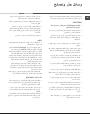
Tableau Caractéristiques des brûleurs et des injecteurs
S
R
A
Ø180
C 31 N1 EX
Tableau 1
Gaz liquide
Gaz naturel
Puissance
thermique
kW (p.c.s.*)
By-pass
1/100
injecteur
1/100
Charge*
g/h
injecteur
1/100
Charge*
l/h
Brûleur à gaz Diamètre
(mm)
Nominale Réduite (mm) (mm) *** ** (mm) G20 G25
Rapide
(Grand) (R)
100 3.00 0.70 41 87 218 214 128 286 332
Semi Rapide
(Intermédiaire)
(S)
75 1.90 0.40 30 70 138 136 104 181 210
Auxiliaire
(Petit) (A)
51 1.00 0.40 30 52 73 71 76 95 111
Pressions
d'alimentation
Nominale (mbar)
Minima (mbar)
Maxima (mbar)
28-30
20
35
37
25
45
20
17
25
25
20
30
CARACTERISTIQUES TECHNIQUES
Dimensions du
four HxLxP
34x39x44 cm
Volume
l 58
Dimensions utiles
du tiroir chauffe-
plats
largeur 42 cm
profondeur 44 cm
hauteur 17 cm
Tension et
fréquence
d’alimentation :
voir plaque signalétique
Brûleurs
adaptables à n’importe quel type de
gaz parmi ceux indiqués sur
l’étiquette collée à l’intérieur du
portillon ou sur la paroi intérieure
gauche (visible après avoir sorti le
tiroir chauffe-plats).
ETIQUETTE
ENERGIE
Directive 2002/40/CE sur l'étiquette
des fours électriques Norme EN
50304 Consommation d’énergie
déclaration Classe convection
Naturelle – fonction four :
=
Statique
Directives Communautaires:
73/23/CEE du 19/02/73 (Basse
Tension) et modifications
successives - 89/336/CEE du
03/05/89 (Compatibilité
Electromagnétique) et modifications
successives -90/369/CEE du
29/06/90 (Gaz) et modifications
successives 93/68/CEE du
22/07/93 et modifications
successives - 2002/96/EC.
* A 15°C et 1013 mbar-gaz sec
** Propane P.C.S. = 50,37 MJ/Kg
*** Butane P.C.S. = 49,47 MJ/Kg
Naturel G20 P.C.S = 37,78 MJ/m
3
Naturel G25 P.C.S = 32,49 MJ/m
3

17
FR
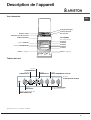
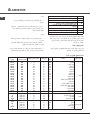
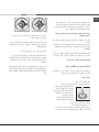
Description de lappareil
Tableau de bord
Vue densemble
*
Nexiste que sur certains modèles
Bouton
MINUTEUR*
Bouton
THERMOSTAT
Voyant
THERMOSTAT
Voyant
FONCTIONNEMENT PLAQUE
Boutons BRULEURS
du plan de cuisson
Bouton
PROGRAMMES
Bougie d'allumage des
BRULEURS GAZ*
Bouton
PLAQUE ELECTRIQUE
Plateau du plan
de cuisson
Grille du plan de cuisson
Tableau de bord
Support GRILLE
Support LECHEFRITE
GLISSIERES
de coulissement
niveau 3
niveau 2
niveau 1
Brûleur à gaz
Pied de réglage
Pied de réglage
niveau 5
niveau 4
Plaque électrique

18
FR
Utilisation du plan de cuisson
Allumage des brûleurs
Un petit cercle plein près de chaque bouton
BRULEUR indique le brûleur associé à ce dernier.
Pour allumer un brûleur du plan de cuisson:
1. approcher une flamme ou un allume-gaz ;
2. pousser sur le bouton du BRULEUR tout en le
tournant dans le sens inverse des aiguilles dune
montre jusquau symbole grande flamme -.
3. pour régler la puissance de la flamme souhaitée,
tourner le bouton BRULEUR dans le sens inverse
des aiguilles dune montre : sur la position minimum
+, sur la position maximum - ou sur une position
intermédiaire.
Si lappareil est équipé dun
allumage électronique* (voir
figure) il faut dabord appuyer
sur la touche dallumage,
repérée par le symbole
correspondant, puis pousser à
fond et tourner en même temps
dans le sens inverse des
aiguilles dune montre le bouton BRULEUR pour
lamener en face du symbole grande flamme, jusquà
lallumage. Il peut arriver que le brûleur séteigne dès
quon lâche le bouton. Dans ce cas, tenter à nouveau en
poussant plus longtemps sur le bouton.
En cas dextinction accidentelle des flammes,
éteindre le brûleur et attendre au moins 1 minute
avant de tenter de rallumer.
Pour éteindre le brûleur, tourner le bouton jusquà la
position darrêt .
Plaque électrique
Pour procéder au réglage, tourner la manette
correspondante dans le sens des aiguilles dune
montre ou dans le sens inverse en choisissant une
des 6 positions possibles :
Position Plaque normale ou rapide
0
Eteint
1
Poissance minimum
2 - 5
Poissance intermédiaires
6
Poissance maximum
Toute position de la manette autre que la position
éteint entraîne lallumage du voyant de
fonctionnement.
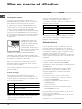
Mise en marche et utilisation
Conseils pratiques pour lutilisation des brûleurs
Pour un meilleur rendement des brûleurs et une
moindre consommation de gaz, utiliser des
casseroles à fond plat, munies de couvercle et dun
diamètre adapté au brûleur :
Brûleur ø Diamètre récipients (cm)
Rapide (R) 24 – 26
Semi-Rapide (S) 16 – 20
Auxiliaire (A) 10 – 14
Pour repérer le type de brûleur adéquat, se référer
aux dessins du paragraphe Caractéristiques des
brûleurs et des injecteurs.
Utilisation du four
Lors de son premier allumage, faire fonctionner le
four à vide, porte fermée, pendant au moins une
heure en réglant la température à son maximum.
Puis éteindre le four, ouvrir la porte et aérer la pièce.
Lodeur qui se dégage est due à lévaporation des
produits utilisés pour protéger le four.
Avant toute utilisation, vous devez impérativement
enlever les films plastiques situés sur les côtés de
lappareil
1. Pour sélectionner le programme de cuisson
souhaité, tourner le bouton PROGRAMMES.
2. Choisir la température conseillée pour ce
programme ou celle quon préfère à laide du bouton
THERMOSTAT.
Un tableau de cuisson sert de guide et indique
notamment les températures conseillées pour
plusieurs préparations culinaires (voir tableau
cuisson au four).
En cours de cuisson, on peut à tout moment :
modifier le programme de cuisson à laide du
bouton PROGRAMMES;
modifier la température à laide du bouton
THERMOSTAT;
programmer la durée et lheure de fin de cuisson
(voir ci-dessous);
interrompre la cuisson en ramenant le bouton
PROGRAMMES sur 0.
Ne jamais poser dobjets à même la sole du four,
lémail risque de sabîmer.
Il faut toujours placer les plats sur la grille fournie
avec lappareil.
*
Nexiste que sur certains modèles

19
FR
Voyant THERMOSTAT
Allumé, il signale la montée en chaleur du four. Il
séteint dès que la température sélectionnée est
atteinte. Le voyant sallume et séteint tour à tour
pour indiquer que le thermostat fonctionne et
maintient la température au degré près.
Eclairage du four
Pour lallumer, amener le bouton PROGRAMMES sur
une position autre que la position 0. Il reste allumé
tant que le four est en marche. Si on tourne le
bouton sur
&
, la lampe sallume sans activer
aucune résistance.
Programmes de cuisson
Pour tous les programmes il est possible de
sélectionner une température comprise entre 50°C et
MAX., sauf pour le programme GRIL, pour lequel il
est préconisé de sélectionner MAX.
=
Programme FOUR STATIQUE
Mise en marche des résistances de voûte et de
sole. Pour cette cuisson traditionnelle mieux vaut
cuire sur un seul niveau : la cuisson sur plusieurs
niveaux entraînerait une mauvaise distribution de la
chaleur.
O
Programme CHALEUR SOLE
Lélément chauffant inférieur est branché. Cette
position est conseillée pour parfaire la cuisson
daliments (placés dans des plats à rôti) qui sont
déjà bien cuits à la surface mais encore mous à
lintérieur ou pour des gâteaux garnis de fruits ou de
confiture qui ont besoin de se colorer modérément à
leur surface. A remarquer que cette fonction ne
permet pas datteindre une température maximum à
lintérieur du four (250°C), il est par conséquent
déconseillé de cuire en maintenant longuement le
four dans cette position à moins quil ne sagisse de
gâteaux qui exigent des températures inférieures ou
égales à 180°C.
?
Programme GRIL
Mise en marche de la résistance de voûte. La
température plutôt élevée et directe du gril permet
de saisir immédiatement les viandes évitant ainsi
quelles ne durcissent en perdant leur jus.
@
Programme DOUBLE GRIL
La résistance de voûte est branchée. La cuisson au
gril est particulièrement recommandée pour les
plats qui exigent une température élevée à leur
surface : côtes de veau et de buf, entrecôtes,
filet, hamburgers, etc...
Les cuissons GRIL et DOUBLE GRIL doivent avoir lieu
porte fermée.
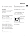
Minuteur*
Pour actionner le Minuteur procéder comme suit :
1. tourner le bouton MINUTEUR et faire un tour
presque complet dans le sens des aiguilles dune
montre " pour remonter la sonnerie;
2. tourner le bouton MINUTEUR dans les sens
inverse des aiguilles dune montre # pour
sélectionner la durée désirée.
Niche inférieure*
Une niche ménagée au-
dessous du four peut
être utilisée pour
entreposer des
accessoires ou des
casseroles. Pour ouvrir
le volet, le faire pivoter
vers le bas (voir figure).
Ne pas stocker de matériel inflammable dans la
niche du bas.
Les surfaces intérieures du tiroir (s'il y en a un)
peuvent devenir chaudes.

20
FR
Quelques conseils utiles pour bien
utiliser votre plaque électrique
Pour éviter toute déperdition de chaleur et ne pas
endommager la plaque, il est conseillé dutiliser des
casseroles à fond plat nayant pas un plus petit
diamètre que celui de la plaque.
Position Plaque normale ou rapide
0
Eteint
1
Cuisson de légumes verts, poissons
2
Cuisson de pommes de terre (à la
vapeur) soupes, pois chiches, haricots
3
Pour continuer la cuisson de grandes
quantités d'aliments, minestrone
4
Rôtir (moyen)
5
Rôtir (fort)
6
Rissoler ou rejoindre l'ébullition en peu
de temps
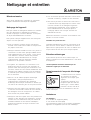
Avant dutiliser les plaques de cuisson pour la
première fois, les faire chauffer pendant 4 minutes à
leur température maximum sans casserole. Au cours
de cette phase initiale, le revêtement protecteur
durcit et atteint sa résistance maximum.
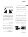
Conseils de cuisson
En cas de cuisson en mode GRIL, placer la
lèchefrite au gradin 1 pour récupérer les jus de
cuisson.
GRIL
Placer la grille au gradin 3 ou 4, enfourner les
plats au milieu de la grille.
Nous conseillons de sélectionner le niveau
dénergie maximum. Ne pas sinquiéter si la
résistance de voûte nest pas allumée en
permanence : son fonctionnement est contrôlé par
un thermostat.
PIZZA
Utiliser un plat en aluminium léger et lenfourner
sur la grille du four.
En cas dutilisation du plateau émaillé, le temps
de cuisson sera plus long et la pizza beaucoup
moins croustillante.
Si les pizzas sont bien garnies, najouter la
mozzarelle quà mi-cuisson.
La page est en cours de chargement...
La page est en cours de chargement...
La page est en cours de chargement...
La page est en cours de chargement...
La page est en cours de chargement...
La page est en cours de chargement...
La page est en cours de chargement...
La page est en cours de chargement...
La page est en cours de chargement...
La page est en cours de chargement...
La page est en cours de chargement...
La page est en cours de chargement...
La page est en cours de chargement...
La page est en cours de chargement...
La page est en cours de chargement...
La page est en cours de chargement...
-
 1
1
-
 2
2
-
 3
3
-
 4
4
-
 5
5
-
 6
6
-
 7
7
-
 8
8
-
 9
9
-
 10
10
-
 11
11
-
 12
12
-
 13
13
-
 14
14
-
 15
15
-
 16
16
-
 17
17
-
 18
18
-
 19
19
-
 20
20
-
 21
21
-
 22
22
-
 23
23
-
 24
24
-
 25
25
-
 26
26
-
 27
27
-
 28
28
-
 29
29
-
 30
30
-
 31
31
-
 32
32
-
 33
33
-
 34
34
-
 35
35
-
 36
36


Indesit C 31 N1 (W) EX Mode d'emploi
- Catégorie
- Fours
- Taper
- Mode d'emploi
dans d''autres langues
- English: Indesit C 31 N1 (W) EX User guide