Skil HD6294B-00 Le manuel du propriétaire
- Catégorie
- Outils électroportatifs
- Taper
- Le manuel du propriétaire

WARNING: To reduce the risk of injury, the user must read and understand the
Owner’s Manual before using this product. Save these instructions for future reference.
AVERTISSEMENT : Afin de réduire les risques de blessure, l’utilisateur doit lire et
comprendre le guide d’utilisation avant d’utiliser cet article. Conservez le présent guide
afin de pouvoir le consulter ultérieurement.
ADVERTENCIA : Para reducir el riesgo de lesiones, el usuario debe leer y comprender
el Manual del operador antes de utilizar este producto. Guarde estas instrucciones para
consultarlas en caso sea necesario.
Owner’s Manual
Guide d’utilisation
Manual del propietario
For Customer Service
Pour le service à la clientèle
Servicio al cliente
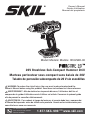
20V Brushless Sub-Compact Hammer Drill
Marteau perforateur sous-compact sans balais de 20V
Taladro de percusión subcompacto de 20 V sin escobillas
1-877-SKIL-999 OR www.skil.com
Model/ Modelo/ Modèle: HD6294B-00

2
TABLE OF CONTENTS
General Power Tool Safety Warnings .............................3-5
Safety Warnings for Hammer Drill ..................................5
Symbols .....................................................6-9
Get to Know Your Hammer Drill ...................................10
Specications .................................................10
Operating Instructions .......................................11-18
Maintenance ...................................................19
Troubleshooting ...............................................20
Limited Warranty of SKIL Cordless Tools ...........................21
WARNING
• Some dust created by power sanding, sawing, grinding, drilling and other construction
activities contains chemicals known to the State of California to cause cancer, birth defects or
other reproductive harm. Some examples of these chemicals are:
– Lead from lead-based paints.
– Crystalline silica from bricks, cement, and other masonry products.
– Arsenic and chromium from chemically-treated lumber.
• Your risk from these exposures varies, depending upon how often you do this type of work.
To reduce your exposure to these chemicals:
– Work in a well-ventilated area.
– Work with approved safety equipment, such as dust masks that are specially designed to
lter out microscopic particles.
– Avoid prolonged contact with dust from power sanding, sawing, grinding, drilling, and
other construction activities. Wear protective clothing and wash exposed areas with soap
and water. Allowing dust to get into your mouth or eyes or to lie on the skin may promote
absorption of harmful chemicals.

3
GENERAL POWER TOOL SAFETY WARNINGS
WARNING Read all safety warnings, instructions, illustrations and specifications
provided with this power tool. Failure to follow all instructions listed
below may result in electric shock, re and/or serious injury.
SAVE ALL WARNINGS AND INSTRUCTIONS FOR FUTURE REFERENCE.
The term “power tool” in the warnings refers to your mains-operated (corded) power tool or
battery-operated (cordless) power tool.
Work area safety
Keep work area clean and well lit. Cluttered or dark areas invite accidents.
Do not operate power tools in explosive atmospheres, such as in the presence of
flammable liquids, gases or dust. Power tools create sparks which may ignite the dust or
fumes.
Keep children and bystanders away while operating a power tool. Distractions can cause
you to lose control.
Electrical safety
Power tool plugs must match the outlet. Never modify the plug in any way. Do not use
any adapter plugs with earthed (grounded) power tools. Unmodied plugs and matching
outlets will reduce risk of electric shock.
Avoid body contact with earthed or grounded surfaces, such as pipes, radiators, ranges
and refrigerators. There is an increased risk of electric shock if your body is earthed or
grounded.
Do not expose power tools to rain or wet conditions. Water entering a power tool will
increase the risk of electric shock.
Do not abuse the cord. Never use the cord for carrying, pulling or unplugging the power
tool. Keep cord away from heat, oil, sharp edges or moving parts. Damaged or entangled
cords increase the risk of electric shock.
When operating a power tool outdoors, use an extension cord suitable for outdoor use.
Use of a cord suitable for outdoor use reduces the risk of electric shock.
If operating a power tool in a damp location is unavoidable, use a ground fault circuit
interrupter (GFCI) protected supply. Use of a GFCI reduces the risk of electric shock.
Personal safety
Stay alert, watch what you are doing and use common sense when operating a power
tool. Do not use a power tool while you are tired or under the influence of drugs, alcohol
or medication. A moment of inattention while operating power tools may result in serious
personal injury.
Use personal protective equipment. Always wear eye protection. Protective equipment
such as a dust mask, non-skid safety shoes, hard hat or hearing protection used for
appropriate conditions will reduce personal injuries.
Prevent unintentional starting. Ensure the switch is in the off-position before connecting
to power source and/or battery pack, picking up or carrying the tool. Carrying power
tools with your nger on the switch or energizing power tools that have the switch on invites
accidents.
Remove any adjusting key or wrench before turning the power tool on. A wrench or a key
left attached to a rotating part of the power tool may result in personal injury.
Do not overreach. Keep proper footing and balance at all times. This enables better
control of the power tool in unexpected situations.

4
Dress properly. Do not wear loose clothing or jewelry. Keep your hair, and clothing away
from moving parts. Loose clothes, jewelry or long hair can be caught in moving parts.
If devices are provided for the connection of dust extraction and collection facilities,
ensure these are connected and properly used. Use of dust collection can reduce dust-
related hazards.
Do not let familiarity gained from frequent use of tools allow you to become complacent
and ignore tool safety principles. A careless action can cause severe injury within a fraction
of a second.
Power tool use and care
Do not force the power tool. Use the correct power tool for your application. The correct
power tool will do the job better and safer at the rate for which it was designed.
Do not use the power tool if the switch does not turn it on and off. Any power tool that
cannot be controlled with the switch is dangerous and must be repaired.
Disconnect the plug from the power source and/or remove the battery pack, if
detachable, from the power tool before making any adjustments, changing accessories,
or storing power tools. Such preventive safety measures reduce the risk of starting the
power tool accidentally.
Store idle power tools out of the reach of children and do not allow persons unfamiliar
with the power tool or these instructions to operate the power tool.
Power tools are dangerous in the hands of untrained users.
Maintain power tools and accessories. Check for misalignment or binding of moving
parts, breakage of parts and any other condition that may affect the power tool’s
operation. If damaged, have the power tool repaired before use. Many accidents are
caused by poorly maintained power tools.
Keep cutting tools sharp and clean. Properly maintained cutting tools with sharp cutting
edges are less likely to bind and are easier to control.
Use the power tool, accessories and tool bits etc. in accordance with these instructions,
taking into account the working conditions and the work to be performed. Use of the
power tool for operations different from those intended could result in a hazardous situation.
Keep handles and grasping surfaces dry, clean and free from oil and grease.
Slippery handles and grasping surfaces do not allow for safe handling and control of the tool in
unexpected situations.
Battery tool use and care
Recharge only with the charger specified by the manufacturer. A charger that is suitable
for one type of battery pack may create a risk of re when used with another battery pack.
Use power tools only with specifically designated battery packs. Use of any other battery
packs may create a risk of injury and re.
When battery pack is not in use, keep it away from other metal objects, like paper clips,
coins, keys, nails, screws or other small metal objects, that can make a connection from
one terminal to another. Shorting the battery terminals together may cause burns or a re.
Under abusive conditions, liquid may be ejected from the battery; avoid contact. If
contact accidentally occurs, flush with water. If liquid contacts eyes, additionally seek
medical help. Liquid ejected from the battery may cause irritation or burns.
Do not use a battery pack or tool that is damaged or modified. Damaged or modied
batteries may exhibit unpredictable behavior resulting in re, explosion or risk of injury.
Do not expose a battery pack or tool to fire or excessive temperature. Exposure to re or
temperature above 265 °F (130 °C) may cause explosion.

5
Follow all charging instructions and do not charge the battery pack or tool outside the
temperature range specified in the instructions. Charging improperly or at temperatures
outside the specied range may damage the battery and increase the risk of re.
Service
Have your power tool serviced by a qualified repair person using only identical
replacement parts. This will ensure that the safety of the power tool is maintained.
Never service damaged battery packs. Service of battery packs should only be performed
by the manufacturer or authorized service providers
SAFETY WARNINGS FOR HAMMER DRILL
Safety instructions for all operations:
Wear ear protectors when impact drilling. Exposure to noise can cause hearing loss.
Hold the power tool by insulated gripping surfaces, when performing an operation
where the cutting accessory or fastener may contact hidden wiring. Cutting accessory
or fastener contacting a "live" wire may make exposed metal parts of the power tool "live" and
could give the operator an electric shock.
Safety instructions when using long drill bits:
Never operate at higher speed than the maximum speed rating of the drill bit. At higher
speeds, the bit is likely to bend if allowed to rotate freely without contacting the workpiece,
resulting in personal injury.
Always start drilling at low speed and with the bit tip in contact with the workpiece.
At higher speeds, the bit is likely to bend if allowed to rotate freely without contacting the
workpiece, resulting in personal injury.
Apply pressure only in direct line with the bit and do not apply excessive pressure. Bits
can bend causing breakage or loss of control, resulting in personal injury.

6
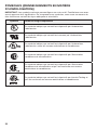
SYMBOLS
Safety Symbols
The purpose of safety symbols is to attract your attention to possible dangers. The safety
symbols and the explanations with them deserve your careful attention and understanding. The
symbol warnings do not, by themselves, eliminate any danger. The instructions and warnings
they give are no substitutes for proper accident prevention measures.
WARNING Be sure to read and understand all safety instructions in this Owner's
Manual, including all safety alert symbols such as “DANGER”, “WARNING”,
and “CAUTION” before using this tool. Failure to following all instructions listed below may result
in electric shock, re, and/or serious personal injury.
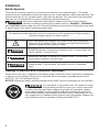
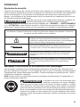
The denitions below describe the level of severity for each signal word. Please read the
manual and pay attention to these symbols.
This is the safety alert symbol. It is used to alert you to potential
personal injury hazards. Obey all safety messages that follow this
symbol to avoid possible injury or death.
DANGER DANGER indicates a hazardous situation which, if not avoided, will
result in death or serious injury.
WARNING WARNING indicates a hazardous situation which, if not avoided,
could result in death or serious injury.
CAUTION CAUTION, used with the safety alert symbol, indicates a hazardous
situation which, if not avoided, will result in minor or moderate
injury.
Damage Prevention and Information Messages
These inform the user of important information and/or instructions that could lead to equipment
or other property damage if they are not followed. Each message is preceded by the word
“NOTICE”, as in the example below:
NOTICE: Equipment and/or property damage may result if these instructions are not followed.
WARNING The operation of any power tools can result in foreign
objects being thrown into your eyes, which can result
in severe eye damage. Before beginning power tool operation, always
wear safety goggles or safety glasses with side shields and a full face
shield when needed. We recommend a Wide Vision Safety Mask for use
over eyeglasses or standard safety glasses with side shields. Always use
eye protection which is marked to comply with ANSI Z87.1.

7
SYMBOLS (CONTINUED)
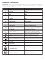
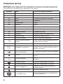
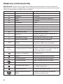
IMPORTANT: Some of the following symbols may be used on your tool. Please study them
and learn their meaning. Proper interpretation of these symbols will allow you to operate the
tool better and more safely.
Symbol Name Designation/Explanation
V Volts Voltage (potential)
AAmperes Current
Hz Hertz Frequency (cycles per second)
WWatt Power
kg Kilograms Weight
min Minutes Time
s Seconds Time
Wh Watt-hours Battery capacity
Ah Ampere-hours Battery capacity
øDiameter Size of drill bits, grinding wheels, etc.
n0No load speed Rotational speed, at no load
nRated speed Maximum attainable speed
…/min Revolutions or reciprocations per
minute (rpm)
Revolutions, strokes, surface speed,
orbits, etc. per minute
OOff position Zero speed, zero torque...
1,2,3,…
Ⅰ,Ⅱ,Ⅲ, Selector settings Speed, torque, or position settings.
Higher number means greater speed
Innitely variable selector with off Speed is increasing from 0 setting
Arrow Action in the direction of arrow
Alternating current (AC) Type or a characteristic of current
Direct current (DC) Type or a characteristic of current
Alternating or direct current
(AC / DC) Type or a characteristic of current
Class II tool Designates Double Insulated Construction
tools.
Protective earth Grounding terminal
Li-ion RBRC seal Designates Li-ion battery recycling
program
Read the instructions Alerts user to read manual

8
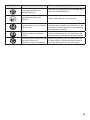
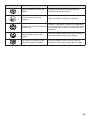
Symbol Name Designation/Explanation
Wear eye protection symbol Alerts user to wear eye protection
Always operate with two hands Alerts user to always operate with two
hands
Do not use the guard for cut-off
operations
Alerts user not to use the guard for
cut-off operations

9
SYMBOLS (CERTIFICATION INFORMATION)
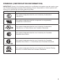
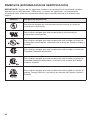
IMPORTANT: Some of the following symbols for certication information may be used on your
tool. Please study them and learn their meaning. Proper interpretation of these symbols will
allow you to operate the tool better and more safely.
Symbol Designation/Explanation
This symbol designates that this tool is listed by Underwriters
Laboratories.
This symbol designates that this component is recognized by
Underwriters Laboratories.
This symbol designates that this tool is listed by Underwriters
Laboratories, to United States and Canadian Standards.
This symbol designates that this tool is listed by the Canadian
Standards Association.
This symbol designates that this tool is listed by the Canadian
Standards Association, to United States and Canadian Standards.
This symbol designates that this tool is listed by the Intertek Testing
Services, to United States and Canadian Standards.

10
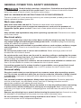
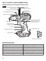
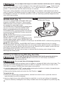
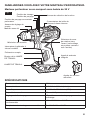
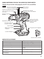
GET TO KNOW YOUR HAMMER DRILL
20V Brushless Sub-Compact Hammer Drill
Fig. 1 Screw-Driving Position
SPECIFICATIONS
Rated Voltage 20V d.c.
No-load Speed 0-500 / 0-1800/min (RPM)
Impact Rate 0-7500 / 0-27000 /min (IPM)
Chuck Capacity 1/2'' (13mm)
Clutch Settings 17 Positions + Drill Mode + Hammer Mode
Recommended operating temperature 14 – 104°F (-10 – 40°C)
Recommended storage temperature 32 – 104°F (0 – 40°C)
Drilling Position
Hammer-Drilling Position
Torque-Adjustment Ring
Keyless Chuck
Chuck Jaws
Variable-Speed
Trigger Switch
Soft Grip
WORKLIGHT
WORKLIGHT Button Integrated Bit Clip
Direction-of-Rotation
(forward/center-lock/
reverse) Selector
Function-
Selection Ring
Two-Speed
Gearbox Switch
Removable Belt Clip

11
OPERATING INSTRUCTIONS
WARNING To reduce the risk of fire, personal injury, and product damage due to
a short circuit, never immerse your tool, battery pack or charger in
fluid or allow a fluid to flow inside them. Corrosive or conductive uids, such as seawater,
certain industrial chemicals, and bleach, or bleach-containing products, etc., can cause a short circuit.
WARNING If any parts are damaged or missing, do not operate this product until
the parts are replaced. Use of this product with damaged or missing parts
could result in serious personal injury.
WARNING Do not attempt to modify this tool or create accessories not
recommended for use with this tool. Any such alteration or modication
is misuse and could result in a hazardous condition leading to possible serious injury.
WARNING
To prevent accidental starting that could cause serious personal injury,
always remove the battery pack from the tool when assembling parts.
This cordless hammer drill must be used only with the battery packs and chargers listed
below:
Battery Pack Charger
2Ah 2Ah 2.5Ah 4Ah 5Ah
SKIL
BY519701
SKIL
BY519702
SKIL
BY519703
SKIL
BY519601
SKIL
BY519603
SKIL
SC535801
SKIL
QC536001
SKIL
QC5359B-02
SKIL
SC5358B-02
NOTICE: Please refer to the battery pack and charger manuals for detailed operating information.
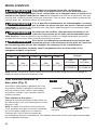
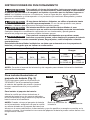
To Attach/Detach Battery Pack
(Fig. 2)
Lock the trigger switch “OFF” on the tool by
placing the direction-of-rotation (forward/center-
lock/reverse) selector in the center position.
To attach the battery pack:
Align the raised rib on the battery pack with the
grooves in the tool, and then slide the battery
pack onto the tool.
NOTICE: When placing the battery pack on the
tool, be sure that the raised rib on the battery
pack aligns with the groove in the tool and that
the latches snap into place properly. Improper
attachment of the battery pack can cause
damage to internal components.
To detach the battery pack:
Depress the battery-release button, located on the front of the battery pack, to release the
battery pack. Pull the battery pack out and remove it from the tool.
WARNING Battery tools are always in operating condition. Therefore, the
direction-of-rotation (forward/center-lock/reverse) selector should
always be locked in the center position when the tool is not in use or when carrying it at
your side.
Fig. 2
Attach
Battery-release
Buttons
Detach

12
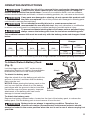
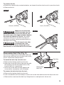
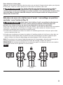
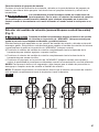
Direction-of-Rotation (Forward/Center-Lock/Reverse) Selector (Fig. 3)
WARNING After tool use, lock the direction-of-rotation selector in the “OFF”
position (center-lock) to help prevent accidental starts and possible injury.
Your tool is equipped with a direction-of-rotation selector, located above the trigger switch. This
selector is designed for changing the direction of rotation of the bit and for locking the trigger in
the “OFF” (center-lock) position.
a. Position the direction-of-rotation selector to the far left of the tool to drill holes or drive the
screws in.
b. Position the direction-of-rotation selector to the far right of the tool to remove screws.
c. Position the switch in the “OFF” (center-lock) position to help reduce the possibility of
accidental starting when the tool is not in use.
NOTICE: To prevent gear damage, always allow the hammer drill to come to a complete stop
before changing the direction of rotation.
NOTE: The hammer drill will not run unless the direction-of-rotation selector is engaged fully to
the left or the right.
Fig. 3
Forward Center-Lock Reverse
Variable-Speed Trigger Switch
(Fig. 4)
Your tool is equipped with a variable-speed
trigger switch. The tool can be turned “ON” or
“OFF” by depressing or releasing the variable-
speed trigger switch.
The variable-speed trigger switch delivers
higher speed with increased trigger pressure
and lower speed with decreased trigger
pressure.
Fig. 4
Variable-Speed
Trigger Switch

13
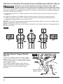
Two-Speed Gearbox Switch (Fig. 5)
Your tool is equipped with a two-speed gearbox designed for operating at low or high speeds.
The slide switch is located on the top of the tool to select either low (marked “1”) or high
(marked “2”) speed.
The low speed (1) provides higher torque and slower speeds for heavy-duty work or for driving
screws, drilling large diameters, or tapping threads. Use the low speed for starting holes
without a center punch, drilling metals or plastic, drilling ceramics, or in applications requiring a
higher torque.
The high speed (2) provides lower torque and faster speeds for lighter drilling work. The high
speed is better for drilling wood and wood composites and for using abrasive and polishing
accessories.
NOTICE: To prevent gear damage, always allow the tool to come to a complete stop before
changing between low speed (1) and high speed (2).
Fig. 5 Two-speed Gearbox Switch
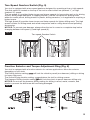
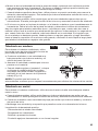
Function Selector and Torque-Adjustment Ring (Fig. 6)
Your tool is equipped with a function selector for various applications. Move the selector
depending on your task.
The Drilling function setting will lock the clutch to permit (non-hammer) drilling or driving
for heavy-duty work.
The Screw-Driving function setting optimizes the tool for driving screws.
The Hammer Drilling function setting will lock the clutch to permit hammer drilling only.
NOTICE: Do not use the hammer drilling setting for drilling in wood, metal, ceramic, and
plastic to prevent the drill/screw bit from being damaged.
17 1
Fig. 6

14
CAUTION Do not adjust the torque or switch functions while the tool is running.
Your tool also features 17 clutch settings for the screw-driving operation . Output torque
will increase as the clutch ring is rotated from 1 to 17. When driving a screw, rst try torque
position 1 and increase until the desired torque is reached.
The proper setting depends on the job and the type of bit, fastener, and material you will be
using. In general, use greater torque for larger screws. If the torque is too high, the screws may
be damaged or broken. For delicate operations, such as removing a partially stripped screw,
use a low torque setting.
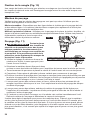
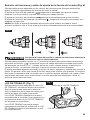
WORKLIGHT (Fig. 7)
Your tool is equipped with a WORKLIGHT light,
located on the base of the tool. This provides
additional light on the surface of the workpiece
for operation in lower-light areas.
The WORKLIGHT will illuminate by default when
the tool is turned on OR if the WORKLIGHT
button is pressed without turning the tool on.
The WORKLIGHT could be turned off manually
by pressing the WORKLIGHT button when the
tool is not running.
NOTE: WORKLIGHT will turn off automatically
after 10 seconds of inactivity if the
WORKLIGHT is turned on by squeezing on the
variable-speed trigger switch. WORKLIGHT will
turn off automatically after 10 minutes of inactivity if the WORKLIGHT is turned on by pressing
the WORKLIGHT button.
NOTE: For safety reasons, the WORKLIGHT button is disabled while the tool is running.
The WORKLIGHT will rapidly ash when the tool and/or battery pack becomes overloaded or
too hot and the internal sensors will turn the tool off. Rest the tool for a while or place the tool
and battery pack separately under air ow for cooling.
The WORKLIGHT will ash more slowly to indicate that the battery pack charge is low.
Recharge the battery pack.
Installing and Removing Bits (Fig. 8a & 8b)
WARNING Do not use the power of the hammer drill while grasping chuck to
loosen or tighten the bit. Friction burn or hand injury is possible if
attempting to grasp the spinning chuck.
WARNING Do not use bits with damaged shanks.
Your tool is equipped with a keyless chuck to tighten or release drill bits in the chuck jaws. The
arrow on the chuck indicates the direction in which to rotate the chuck body in order to lock
("CLOSE") or unlock ("OPEN") the chuck jaws on the drill bit.
a. Lock the trigger switch “OFF” on the tool by placing the direction-of-rotation (forward/center-
lock/reverse) selector in the center position.
b. Remove the battery pack and select the Drill Position “ ”.
To install the bit:
a. Rotate the chuck body counterclockwise, viewed from chuck end, to open the chuck to
approximately the drill bit diameter.
b. Insert a clean bit up to the drill-bit utes for small bits, or as far as it will go for large bits.
Close the chuck by rotating the chuck body clockwise and securely tighten it by hand (Fig. 8a).
Fig. 7
WORKLIGHT Button
WORKLIGHT

15
To remove the bit:
a. Rotate the chuck body counterclockwise, as viewed from the chuck end, to open the chuck.
b. Remove the bit.
OPEN
CLOSE
OPEN
CLOSE
Fig. 8a
Unlock ("OPEN") Lock ("CLOSE")
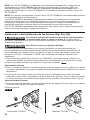
WARNING Make sure to insert the
drill bit straight into the
chuck jaws. Do not insert the drill bit into
the chuck jaws at an angle and then tighten
the chuck as shown in Fig. 8b. This could
cause the drill bit to be thrown from the tool,
resulting in possibly serious personal injury or
damage to the chuck.
WARNING The bit may be hot after
prolonged use. Use
protective gloves when removing the bit
from the tool, or first allow the bit to cool down.
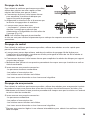
Removable Belt Clip (Fig. 9)
Your tool is shipped with a removable belt clip
that can be positioned on the either side of the
tool for convenient transportation.
To install the belt clip onto the tool:
a. Remove the battery pack from the tool.
b. Align the rib and the hole of the belt clip with
the opening and the threaded hole on the
base of the tool, respectively.
c. Insert the screw and securely tighten the
screw with a screwdriver (not included).
To remove the belt clip from the tool:
a. Remove the battery pack from the tool.
b. Use a screwdriver (not included) to loosen the screw that attaches the belt clip to the tool.
c. Remove the screw and the belt clip. Keep them in a safe place for future use.
Fig. 8b
Fig. 9
Opening
Removable
Belt Clip
Rib

16
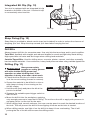
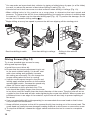
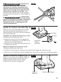
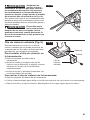
Integrated Bit Clip (Fig. 10)
Your tool is equipped with an integrated bit clip
located on the back of the tool. Use the bit clip
to conveniently store hex bits.
Strap Fixing (Fig. 10)
Strap xing is provided to attach a wrist strap (not included) in order to reduce the chances of
dropping your tool. Wrap the strap around your hand when carrying the tool.
Drill Bits
Always inspect drill bits for excessive wear. Use only bits that are sharp and in good condition.
Twist Bits: Available with straight and reduced shanks for wood and light-duty metal drilling.
High-speed bits cut faster and last longer when drilling hard materials.
Carbide-Tipped Bits: Used for drilling stone, concrete, plaster, cement, and other unusually
hard nonmetal materials. Use continuous, heavy feed pressure when using carbide-tipped bits.
Drilling (Fig. 11)
WARNING Always wear safety
goggles or safety glasses
with side shields during power tool
operation or when blowing dust. If the
operation is dusty, also wear a dust mask.
a. Check that the direction-of-rotation selector
is at the correct setting (forward or reverse).
b. Secure the material to be drilled in a vise or
with clamps to keep it from turning as the
drill bit rotates.
c. Hold the drill rmly and place the bit at the
point to be drilled.
d. Squeeze the variable-speed trigger switch to
start the drill.
e. Move the drill bit into the workpiece, applying
only enough pressure to keep the bit “biting”. Do not force the drill or apply side pressure to
elongate a hole. Let the tool do the work.
f. When drilling hard, smooth surfaces, rst use a center punch to mark the desired location of
the hole. This will prevent the drill bit from slipping off-center as the hole is started.
g. When drilling metals, use light oil on the drill bit to keep it from overheating. The oil will
prolong the life of the bit and increase the drilling action.
Fig. 11
Fig. 10
Strap Fixing
Bit Clip

17
h. If the bit jams in the workpiece or if the drill stalls, stop the tool immediately. Remove the bit
from the workpiece and determine the reason for jamming.
There are two rules for drilling hard materials. First, the harder the material, the greater the
pressure you need to apply to the tool. Second, the harder the material, the slower the speed
should be. If the hole to be drilled is fairly large, drill a smaller hole rst, then enlarge to the
required size with a larger bit; it’s often faster in the long run than drilling a larger hole initially.
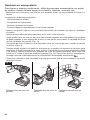
Wood Drilling
For maximum performance, use high-speed
steel or brad-point bits for wood drilling.
a. Begin drilling at a very low speed to prevent
the bit from slipping off the starting point.
b. Increase speed as the drill bit bites into the
material.
c. When drilling “through” holes, place a block
of wood behind the workpiece to prevent
ragged or splintered edges on the back
side of the workpiece (Fig. 12).
NOTICE: Bits may overheat unless they are
reversed and pulled out frequently to clear
chips from the utes.
Metal Drilling
For maximum performance, use high-speed steel bits for metal or steel drilling.
a. When drilling metals, use light oil on the drill bit to keep it from overheating. The oil will
prolong the life of the bit and increase the drilling efciency.
b. Begin drilling at a very low speed to prevent the bit from slipping off the starting point.
c. Maintain a speed and a pressure that allow cutting without overheating the bit.
Applying too much pressure will:
– Overheat the drill.
– Wear the bearings.
– Bend or burn bits.
– Produce off-center or irregularly shaped holes.
Masonry Drilling
For maximum performance, use carbide-tipped masonry bits when drilling holes in brick, tile,
concrete, etc.
• Maintain a speed and a pressure that allow cutting without overheating the bit or drill.
Applying too much pressure will:
– Overheat the drill.
– Wear the bearings.
– Bend or burn bits.
– Produce off-center or irregular-shaped holes.
• Apply light pressure and medium speed for best results in brick.
• Apply additional pressure for hard materials such as concrete.
Fig. 12

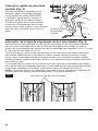
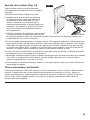
18
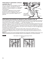
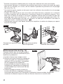
• You can make an improvised dust collector by taping a folded piece of paper (or a le folder)
to a wall, to reduce the amount of dust when drilling in walls (Fig. 13).
• A tennis ball cut in half can serve as a dust collector when drilling in ceilings (Fig. 13).
• When drilling holes in tile, practice on a scrap piece to determine the best speed and
pressure. To prevent the drill bit from skidding/sliding, rst apply two pieces of masking tape
to create an “X” shape over the intended drilling spot (Fig. 13). To prevent tile damage, do not
run the tool in hammer drilling setting .
• Begin drilling at a very low speed to prevent the bit from slipping off the starting point.
Fig. 13
Driving Screws (Fig. 14)
Try to use standard-type screws for easy
driving and improved grip.
a. Install the correct driver bit.
b. Ensure that the torque-adjustment ring is set
to the most suitable setting. If in doubt, start
with a low setting and gradually increase
the setting as necessary. Do not change the
torque setting when the tool is running.
c. Use the correct speed range for the job and
initially apply minimal pressure to the variable
speed trigger switch. Increase the speed only
when full control can be maintained.
d. It is advisable to drill a pilot hole rst. This
hole should be slightly longer than the screw
to be driven and just smaller than the shank diameter of the screw. The pilot hole will act as
a guide for the screw and will also make tightening the screw less difcult. When screws are
positioned close to an edge of the material, a pilot hole will also help to prevent splitting of
the wood.
e. Use a countersinking bit (sold separately) to accommodate the screw head so that it does
not protrude from the surface.
f. Keep sufcient pressure on the drill to prevent the bit from turning out of the screw head.
The
screw head can easily become damaged, making it difcult to drive home or remove the screw.
g. To stop the drill/driver, release the trigger switch and allow the tool to come to a complete
stop.
Dust-free drilling in walls Dust-free drilling in ceilings Drilling in tiles without
skidding
Fig. 14

19
Automatic Spindle Lock
The automatic spindle lock allows you to use it as a manual screwdriver. You can give an extra
twist to rmly tighten a screw, loosen a very tight screw, or continue working when the battery
charge is depleted. For manual screwdriver purposes, the chuck is automatically locked when
the tool is off.
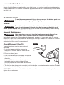
MAINTENANCE
WARNING To avoid serious personal injury, always remove the battery pack from
the tool when cleaning or performing any maintenance.
Service
WARNING Preventive maintenance performed by unauthorized personnel may
result in misplacing of internal wires and components which could
cause serious hazard. We recommend that all tool service be performed by a SKIL Factory
Service Center or Authorized SKIL Service Station.
General Maintenance
WARNING When servicing, use only identical replacement parts. Use of any
other parts could create a hazard or cause product damage.
Periodically inspect the entire product for damaged, missing, or loose parts such as screws,
nuts, bolts, caps, etc. Tighten securely all fasteners and caps and do not operate this product
until all missing or damaged parts are replaced. Please contact customer service or an
authorized service center for assistance.
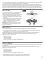
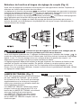
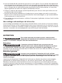
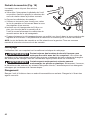
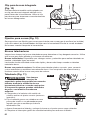
Chuck Removal (Fig. 15)
The keyless chuck can be removed and
replaced.
a. Lock the trigger switch by placing the
direction-of-rotation selector in the center
position.
b. Open the chuck jaws.
c. Use a screwdriver (not included) to remove
the chuck screw by turning it in a clockwise
direction.
d. Insert a 5/16-in. or larger hex key (not
included) into the chuck of the tool and
securely tighten the chuck jaws around the
hex key.
e. Tap the hex key sharply with a mallet (not included) in a counterclockwise direction. This will
loosen the chuck for easy removal.
NOTICE: The chuck screw has left-handed threads. Attach a new chuck to the spindle and
tighten the chuck screw.
Fig. 15

20
Cleaning
The tool may be cleaned most effectively with compressed dry air.
WARNING Always wear safety goggles when cleaning tools with compressed air.
The guard system, ventilation openings, and switch levers must be kept
clean and free of foreign matter. Do not attempt to clean by inserting pointed objects through
openings.
WARNING Certain cleaning agents and solvents damage plastic parts. Some of
these are: gasoline, carbon tetrachloride, chlorinated cleaning solvents,
ammonia and household detergents that contain ammonia.
Storage
Store the tool indoors in a place that is inaccessible to children. Keep away from corrosive
agents.
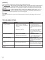
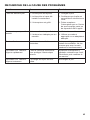
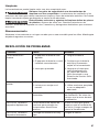
TROUBLESHOOTING
Problem Cause Remedy
Tool will not start. 1. Battery pack is depleted. 1. Charge the battery.
2. Battery pack is not installed
properly. 2. Conrm that the battery is
locked and secured to the
tool.
3. Burned out switch. 3. Have the switch replaced
by an Authorized SKIL
Service Center or Service
Station.
Bit cannot be installed. 1. Chuck is not released. 1. Release the chuck.
2. Bit does not t the chuck. 2. Use an appropriate bit or
use a suitable adaptor.
Motor overheating Ventilation slots are obstructed. Clean and clear the
ventilation slots. Do not cover
the slots with hand during
operation.
WORKLIGHT ashes
rapidly. The tool has stopped working to
protect internal electronics. Release the trigger switch,
wait for the tool to cool down,
then and start the tool again.
WORKLIGHT ashes
slowly. The battery charge is very low. Charge the battery.
La page est en cours de chargement...
La page est en cours de chargement...
La page est en cours de chargement...
La page est en cours de chargement...
La page est en cours de chargement...
La page est en cours de chargement...
La page est en cours de chargement...
La page est en cours de chargement...
La page est en cours de chargement...
La page est en cours de chargement...
La page est en cours de chargement...
La page est en cours de chargement...
La page est en cours de chargement...
La page est en cours de chargement...
La page est en cours de chargement...
La page est en cours de chargement...
La page est en cours de chargement...
La page est en cours de chargement...
La page est en cours de chargement...
La page est en cours de chargement...
La page est en cours de chargement...
La page est en cours de chargement...
La page est en cours de chargement...
La page est en cours de chargement...
La page est en cours de chargement...
La page est en cours de chargement...
La page est en cours de chargement...
La page est en cours de chargement...
La page est en cours de chargement...
La page est en cours de chargement...
La page est en cours de chargement...
La page est en cours de chargement...
La page est en cours de chargement...
La page est en cours de chargement...
La page est en cours de chargement...
La page est en cours de chargement...
La page est en cours de chargement...
La page est en cours de chargement...
La page est en cours de chargement...
La page est en cours de chargement...
La page est en cours de chargement...
La page est en cours de chargement...
La page est en cours de chargement...
La page est en cours de chargement...
La page est en cours de chargement...
La page est en cours de chargement...
La page est en cours de chargement...
La page est en cours de chargement...
La page est en cours de chargement...
La page est en cours de chargement...
La page est en cours de chargement...
La page est en cours de chargement...
-
 1
1
-
 2
2
-
 3
3
-
 4
4
-
 5
5
-
 6
6
-
 7
7
-
 8
8
-
 9
9
-
 10
10
-
 11
11
-
 12
12
-
 13
13
-
 14
14
-
 15
15
-
 16
16
-
 17
17
-
 18
18
-
 19
19
-
 20
20
-
 21
21
-
 22
22
-
 23
23
-
 24
24
-
 25
25
-
 26
26
-
 27
27
-
 28
28
-
 29
29
-
 30
30
-
 31
31
-
 32
32
-
 33
33
-
 34
34
-
 35
35
-
 36
36
-
 37
37
-
 38
38
-
 39
39
-
 40
40
-
 41
41
-
 42
42
-
 43
43
-
 44
44
-
 45
45
-
 46
46
-
 47
47
-
 48
48
-
 49
49
-
 50
50
-
 51
51
-
 52
52
-
 53
53
-
 54
54
-
 55
55
-
 56
56
-
 57
57
-
 58
58
-
 59
59
-
 60
60
-
 61
61
-
 62
62
-
 63
63
-
 64
64
-
 65
65
-
 66
66
-
 67
67
-
 68
68
-
 69
69
-
 70
70
-
 71
71
-
 72
72


Skil HD6294B-00 Le manuel du propriétaire
- Catégorie
- Outils électroportatifs
- Taper
- Le manuel du propriétaire
dans d''autres langues
- English: Skil HD6294B-00 Owner's manual
- español: Skil HD6294B-00 El manual del propietario