Dometic AE Power Patio Awning Top Adapter 4.88 Radius Kit 3108907.068# Guide d'installation
- Taper
- Guide d'installation

Form No. 3312059.000 10/07
(French 3312067.000)
©2007 Dometic Corporation
LaGrange, IN 46761
Model
3108907.068#
USA
SERVICE OFFICE
Dometic Corporation
2320 Industrial Parkway
Elkhart, IN 46516
574-294-2511
CANADA
Dometic Corporation
46 Zatonski, Unit 3
Brantford, ON N3T 5L8
CANADA
519-720-9578
For Service Center
Assistance Call:
800-544-4881
RECORD THIS UNIT INFORMATION FOR
FUTURE REFERENCE:
Model Number
Serial Number
Date Purchased
This manual must be read and
understood before installation,
adjustment, service, or mainte-
nance is performed. This unit
must be installed by a qualied
service technician. Modication
of this product can be extremely
hazardous and could result in
personal injury or property dam-
age.
Assurez-vous de lire et de comprendre ce
manuel avant de procéder à l'installation,
à des réglages, à de l'entretien ou
à des réparations. L'installation de
ce produit doit être effectuée par un
réparateur qualié. Toute modication
de ce produit peut être extrêmement
dangereuse et entraîner des blessures
ou des dommages matériels.
Important: These Instructions must
stay with unit. Owner read carefully.
INSTALLATION
INSTRUCTIONS
Kit, Top Adapter 4.88 Radius
Part No. 3108907.068#

2
Power Patio Top Kit Adapter Installation Instructions
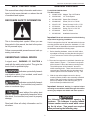
SAFETY INSTRUCTIONS
This manual has safety information and instruc-
tions to help users eliminate or reduce the risk
of accidents and injuries.
RECOGNIZE SAFETY INFORMATION
This is the safety-alert symbol. When you see
this symbol in this manual, be alert to the poten-
tial for personal injury.
Follow recommended precautions and safe op-
erating instructions.
UNDERSTAND SIGNAL WORDS
A signal word , WARNING OR CAUTION is
used with the safety-alert symbol. They give the
level of risk for potential injury.
indicates a potentially hazard-
ous situation which, if not avoided, could result
in death or serious injury.
indicates a potentially hazard-
ous situation which, if not avoided, may result in
minor or moderate injury.
used without the safety alert
symbol indicates, a potentially hazardous situa-
tion which, if not avoided, may result in property
damage.
Read and follow all safety information and in-
structions.
Installation Instructions
For 895100X.400# Hardware
This Kit Contains:
2 - 3108907.076# Adapter, Top 4.88” Radius
4 - 3108708.094 1/2" Foam Spacer
4 - 3312048.055# Spacer, Back Channel
4 - 3104499.045 Screw, S14-10 x 1” HHW
4 - 3104176.155 Screw, Hexcap 1/4-20 x 1” SS
4 - 317534.006 Nut, Lock w/Insert 1/4-20 SS
8 - 3104499.003 Screw, S14-10 x 1.50” SS
6 - 317228.008 Wire Tie, Black
1 - 3312059.000 Installation Instructions
Important: Read and understand all of the following
steps before beginning installation.
This kit is designed to t a 4.88” side wall radius for the top
mounting bracket and will space the hardware 1/2” from
side wall. Follow the installation instructions provided with
the hardware and add the following steps:
1. Before installing hardware, mount the 4.88” radius
top adapter to the top mounting bracket using the 1”
x 1/4-20 screws and 1/4-20 lock nut provided with
this kit.
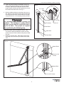
2. Place two foam spacers on each back channel at po-
sitions shown in Figure 1. The bottom foam spacer
will be located 2” above the bottom mounting holes.
The middle spacer will be located 2” above the
middle mounting holes. These foam blocks can be
removed later (if desired) after the aluminum back
channel spacer blocks are installed. See Fig. 1 & 2
3. With the top radius adapter secured on the top
mounting bracket, hold the arm assembly at desired
position and mark location of holes in top adapter.
Secure top adapter to side wall using two (2) 1” x
S14-10 screws provided with this kit.
Important: Structural backing is required where
mounting screws will be installed through side wall for
securing top adapter and middle and lower spacers.
The following step involves opening the
hardware. The hardware is spring loaded.
Extreme caution must be used when remov-
ing the tie wires. Two people are required
when performing the following step.

3
Power Patio Top Kit Adapter Installation Instructions
4. With one person holding the hardware closed, the
other person should carefully remove the hardware
tie wraps. When the tie wraps are removed, both
people should carefully open the hardware to access
the middle and bottom holes. See Fig. 2
5. With the middle and bottom mounting holes now vis-
ible, slide the back channel spacer blocks behind the
mounting holes and secure the hardware to the wall
using the S14-10 x 1.50” mounting screws provided.
The following step involves opening the
hardware. The hardware is spring loaded.
Extreme caution must be used when remov-
ing the tie wires. Two people are required
when performing the following step.
6. With two people, push the hardware closed. With
one person holding the hardware closed, the other
person must secure the hardware using the provided
wire ties.
7. Repeat on opposite side. Make wiring connections
according to the instructions provided with the hard-
ware.
FIG. 1
FIG. 2
Top Adapter
1"xS14-10
1/4" lock Nut
1"x 1/4-20
(3)Tire Wires
Foam Block
Coach Wall
Foam Block
Spacer Block
S14-10 x1.50"
Screws
Spacer Block
S14-10 x1.50" Screws
-
 1
1
-
 2
2
-
 3
3