
106919_RevA
www.kaliastyle.com
Conserver ce guide après l’installation car il contient des informations utiles
pour le service et la garantie.
Keep these instructions after you have nished the installation, it contains useful
information regarding service and warranty.
Numéro de série/Serial number
Instructions d’installation - Garantie
Installation Instructions - Warranty
08/23
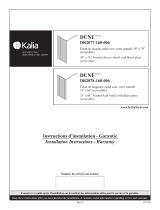
106832
Valve 1/2” de type T/P
AQUATONIKMC à
boutons-poussoirs
3 voies
3-way AQUATONIK
™
type T/P 1/2”
push-button valve
106833
Valve 1/2” de type T/P
AQUATONIKMC à
boutons-poussoirs
2 voies
2-way AQUATONIK
™
type T/P 1/2”
push-button valve

2
106919_RevA
Merci d’avoir choisi un produit Kalia et de faire
conance à notre entreprise.
Kalia a une philosophie d’affaires basée sur
des valeurs fondamentales dont l’innovation et
l’excellence ainsi qu’un service personnalisé
adapté aux exigences d’aujourd’hui et de demain.
Nous sommes convaincus que ce produit saura
vous plaire et surpassera vos exigences en termes
de abilité et durabilité. Nous sommes là pour
vous!
Dans ce guide vous trouverez toute l’information
nécessaire à l’installation et au bon fonctionnement
de votre produit Kalia.
Dans le but d’assurer une installation et une
utilisation optimales veuillez prendre quelques
minutes pour étudier ce guide.
En cas de problème d’installation ou de
performance, veuillez communiquer avec nous au
numéro sans frais 1 877 GO KALIA (1 877 465-
2542) ou par courriel au [email protected].
Nous vous remercions encore une fois d’avoir
choisi un produit Kalia.
Merci d’avoir choisi Kalia !
Thank you for choosing a Kalia product and for
placing your trust in our company.
The Kalia business philosophy is based on a solid
core of values focused on providing innovation
and excellence as well as a personalized service
designed to meet the changing needs of today and
tomorrow.
We are convinced that you will be fully satised
with your new Kalia product and that it will
exceed your expectations in terms of reliability
and durability. At Kalia we put our expertise to
work for you!
This guide contains all the necessary information
for the installation and proper use of your Kalia
product. To ensure the smooth installation and
optimal use of your product, we recommend
taking a few moments to study the information
provided in this guide.
In the event that you should encounter a problem
related to the installation or the performance of
this product, please contact us at our toll-free line
1 877 GO KALIA (1-877-465-2542) or by email
at: [email protected].
Thank you once again for choosing Kalia.
Thank you for choosing Kalia!
Renseignements importants
IMPORTANT
- Lire attentivement le présent guide avant
l’installation.
- Assurez-vous d’avoir tous les outils et
matériaux nécessaires à l’installation.
- Vérier que toutes les pièces illustrées à la
section Schéma des pièces sont incluses et
qu’aucune pièce n’est endommagée. Si un
problème survient, le signaler immédiatement
au vendeur.
- Respecter tous les codes de plomberie et de
bâtiment locaux.
Kalia se réserve le droit d’apporter toute
modication au design du produit et ceci sans
préavis. Utiliser le manuel d’installation fourni
dans l’emballage.
Kalia n’est pas responsable des problèmes causés
par une installation non conforme aux directives
énoncées dans le présent guide.
Bonne installation !
Important Information
IMPORTANT
- Read this guide before proceeding with the
installation.
- Make sure you have all the tools and materials
needed for installation.
- Make sure all the parts shown in the Parts
Diagram section are included and in good
condition. If there is a problem, report it
immediately to the seller.
- Respect all local plumbing and building
codes.
Kalia reserves the right to make any changes to
the design of the product, without notice. Use the
installation instruction supplied with the product.
Kalia is not responsible for problems caused by
an installation not executed in accordance with
the directions given in this guide.
Good installation!

3
106919_RevA
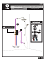
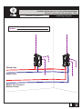
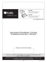
TB2
Système de douche thermostatique à boutons poussoirs 2 voies
2-way push buttons thermostatic shower system
Schéma de plomberie Plumbing Diagram
Froid
Cold
Ne pas retirer ce bouchon
Do not remove this cap
Chaud
Hot
2
1
Conguration 2 voies
2-way conguration
2
1
EXIT / SORTIE
EXIT / SORTIE
CHAUD
HOT
FROID
COLD

4
106919_RevA
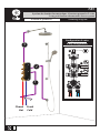
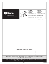
TB3
Système de douche thermostatique à boutons poussoirs 3 voies
3-way push buttons thermostatic shower system
Schéma de plomberie Plumbing Diagram
Froid
Cold
Chaud
Hot
CHAUD
HOT
FROID
COLD
2
1
3EXIT / SORTIE
EXIT / SORTIE
EXIT / SORTIE
Conguration 3 voies
3-way conguration
2
1
3

5
106919_RevA
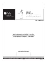
Système de douche avec 2 valves thermostatiques
Shower system with 2 thermostatic valves
Schéma de plomberie Plumbing Diagram
Chaud / Hot
Froid / Cold
Retour vers l’entrée /
Return to main
Eau mitigée pour alimenter les composantes
Mixed water to feed coponents

6
106919_RevA
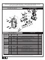
Assemblage
Assembly #Numéro de pièce
Part Number Description Qté totale
Total qty
1
1a 106957 Gabarit de plastique / Plastic template 1
2 106958 Niveau / Level 3
- 3 106959 Vis M6 x 30mm / Mechanical Screw M6 x 30mm 4
- 4a 106960 Corps de la valve / Valve body 1
1
5 101769 Bouchon de sortie / Outlet cap 1
6 106962 Rondelle d'étanchéité / Sealing ring 1
- 7 106963 Cartouche ON-OFF / ON-OFF cartridge 1
- 8 106964 Cartouche ON-OFF (haut débit) / ON-OFF cartridge (High-flow) 1
- 9 106965 Écrou de cartouche ON-OFF / ON-OFF Cartridge nut 2
- 10 106966 Écrou de cartouche thermostatique / Thermostatic cartridge nut 1
1
11 104079 Cartouche thermostatique / Thermostatic cartridge 1
21 107246 Pin pour cartouche / Cartridge pin 1
- 12 106968 Rondelle d'étanchéité (avec grillage) / Sealing ring (with grid) 2
2
13 106970 Valve anti-retour / Check Valve 1
14 106971 Joint torique OD26xD2 / O-Ring OD26xD2 1
15 106972 Corps de valve d'arrêt / Shut-off valve body 1
16 106973 Joint torique OD9xD1.9 / O-Ring OD9xD1.9 1
17 106974 Piston / Plunger 1
18 106975 Joint torique OD14xD2 / O-Ring OD14xD2 1
19 106976 Anneau de retenue / Retaining ring 1
- 20 107016 Vis de montage / Mounting Screw 3
* XXX signifie que la couleur du fini doit être spécifiée. / XXX means that the finish color must be specified.
Ensemble de valve d'arrêt / Shut-off valve assembly
106969
2 ways thermostatic Push Valve 1/2 106833
106956
Ensemble Gabarit de plastique / Plastic template assembly
106961
Ensemble de bouchon de sortie / Outlet cap assembly
107245
Ensemble de cartouche / Cartridge assembly
3
20
20
9
8
10
18
17
15
14
13
12
16
19
10
7
9
7
8
7
1a
4a
4b
2
3
1b
2
5 6
5 6
18
17
15
14
13
12
16
19
11
21
11
21
VALVE 1/2” DE TYPE T/P AQUATONIKMC À BOUTONS-POUSSOIRS 2 VOIES
2-WAY AQUATONIK
™
TYPE T/P 1/2” PUSH-BUTTON VALVE
Liste des pièces Parts List
Schéma des pièces Parts Diagram
106833

7
106919_RevA
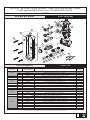
Assemblage
Assembly #Numéro de pièce
Part Number Description Qté totale
Total qty
1
1b 106978 Gabarit de plastique / Plastic template 1
2 106958 Niveau / Level 3
- 3 106959 Vis M6 x 30mm / Mechanical Screw M6 x 30mm 6
- 4b 106979 Corps de la valve / Valve body 1
2
5 101769 Bouchon de sortie / Outlet cap 1
6 106962 Rondelle d'étanchéité / Sealing ring 1
- 7 106963 Cartouche ON-OFF / ON-OFF cartridge 2
- 8 106964 Cartouche ON-OFF (haut débit) / ON-OFF cartridge (High-flow) 1
- 9 106965 Écrou de cartouche ON-OFF / ON-OFF Cartridge nut 3
- 10 106966 Écrou de cartouche thermostatique / Thermostatic cartridge nut 1
1
11 104079 Cartouche thermostatique / Thermostatic cartridge 1
21 107246 Pin pour cartouche / Cartridge pin 1
- 12 106968 Rondelle d'étanchéité (avec grillage) / Sealing ring (with grid) 2
2
13 106970 Valve anti-retour / Check Valve 1
14 106971 Joint torique OD26xD2 / O-Ring OD26xD2 1
15 106972 Corps de valve d'arrêt / Shut-off valve body 1
16 106973 Joint torique OD9xD1.9 / O-Ring OD9xD1.9 1
17 106974 Piston / Plunger 1
18 106975 Joint torique OD14xD2 / O-Ring OD14xD2 1
19 106976 Anneau de retenue / Retaining ring 1
- 20 107016 Vis de montage / Mounting Screw 5
* XXX signifie que la couleur du fini doit être spécifiée. / XXX means that the finish color must be specified.
3 ways thermostatic Push Valve 1/2 106832
Ensemble de valve d'arrêt / Shut-off valve assembly
106961
106977
Ensemble Gabarit de plastique / Plastic template assembly
Ensemble de bouchon de sortie / Outlet cap assembly
106969
107245
Ensemble de cartouche / Cartridge assembly
3
20
20
9
8
10
18
17
15
14
13
12
16
19
10
7
9
7
8
7
1a
4a
4b
2
3
1b
2
5 6
5 6
18
17
15
14
13
12
16
19
11
21
11
21
VALVE 1/2” DE TYPE T/P AQUATONIKMC À BOUTONS-POUSSOIRS 3 VOIES
3-WAY AQUATONIK
™
TYPE T/P 1/2” PUSH-BUTTON VALVE
Liste des pièces Parts List
Schéma des pièces Parts Diagram
106832

8
106919_RevA
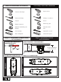
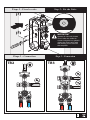
Outils et matériaux nécessaires Necessary Tools and Materials
Visseuse électrique
Tournevis Phillips
Crayon
Ruban à mesurer
Ruban d’étanchéité pour
letage
Clé à molette
Pince multiprise
Impact driver
Phillips screwdriver
Pencil
Measuring tape
Thread sealant
tape
Adjustable wrench
Channellock plier
Étape 1 - Déterminer l’emplacement
et l’orientation Step 1 - Determine location
and orientation
MUR STANDARD / STANDARD WALL
ENTRÉE D’EAU PRINCIPALE /
MAIN WATER VALVE
POSSIBILITÉ D’ORIENTATION / POSSIBILITY OF ORIENTATION
83 mm to/à 108mm
(3 1/4’’ to/à 4 1/4’’)
Fermé
O
orientation 1
orientation 2orientation 3

9
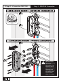
106919_RevA
TB2 TB3
EXIT / SORTIE2
EXIT / SORTIE
1
CHAUD
HOT
FROID
COLD
EXIT /
SORTIE
3
EXIT / SORTIE
1
EXIT / SORTIE
2
CHAUD
HOT
FROID
COLD
IMPORTANT
Ajuster la valve de niveau
avec l’aide des outils de
niveau intégrées au gabarit./
Adjust the level valve with
the leveling tools built into
the template.
Step 3 - Connexion
Étape 3 - Connection
Étape 2 - Fixer la valve Step 2 - Fix the Valve

10
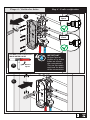
106919_RevA
FROID
COLD
CHAUD
HOT
2
1
3
IMPORTANT
Retirer les
cartouches avant
de souder et les
replacer (après
refroidissement)./
Remove both
cartridges before
the welding and
replace them
(after it’s cooler).
CHAUD
HOT
2
1
3
FROID
COLD
Step 3 - TB2/TB3 Connexion
Étape 3 - Connection TB2/TB3

11
106919_RevA
CHAUD
HOT
FROID
COLD
1
2
3
CHAUD
HOT
1
2
3
FROID
COLD
IMPORTANT
Activer l’eau et
vérifier s’il y a des
fuites au niveau
des connexions./
Turn on the water
and look for leaks
at the connexions.
ENTRÉE D’EAU PRINCIPALE /
MAIN WATER VALVE
Ouvert
Open
B
A
C
Ouvert/
Open
Fermé/
Close
Step 4 - Leaks verication
Étape 4 - Vérier les fuites

Garantie Warranty
GARANTIE À VIE LIMITÉE POUR LES SYSTÈMES DE
DOUCHE KALIA À L’EXCEPTION DES COMPOSANTES
SUIVANTES DONT LA GARANTIE EST POUR 1 AN :
• Jets de corps
• tête de pluie
• pomme de douche
• douchette
• Boyau flexiBle
• rail pour douchette
• Bec de Bain mural
avec déviateur
Kalia inc. garantit à vie sa robinetterie de salle de bain
contre tout défaut de matériel ou de fabrication dans des
conditions normales d’utilisation et d’entretien tant et aussi
longtemps que l’acheteur/propriétaire possède sa résidence.
Pour information sur la garantie complète,
visitez le www.KaliaStyle.com.
LIFETIME LIMITED WARRANTY ON KALIA SHOWER
SYSTEMS EXCEPT 1 YEAR LIMITED WARRANTY FOR
THE FOLLOWING COMPONENTS :
• Body jets
• Rainhead
• showeRhead
• handshoweR
• FlexiBle hose
• wallBaR
• tuB spout with
diveRteR
Kalia Inc. guarantees all aspects of its bathroom faucets
to be free of defects in material and workmanship for
normal residential use for as long as the original consumer/
purchaser owns his or her home.
For complete warranty information,
visit www.KaliaStyle.com.
Imprimé en Chine / Printed in China 106919_RevA
-
 1
1
-
 2
2
-
 3
3
-
 4
4
-
 5
5
-
 6
6
-
 7
7
-
 8
8
-
 9
9
-
 10
10
-
 11
11
-
 12
12


dans d''autres langues
- English: Kalia 106832 User guide
Documents connexes
-
Kalia BF1432-110-101 Mode d'emploi
-
 Kalia DR2078-160-006 Guide d'installation
-
 Kalia BF1338-110-100 Mode d'emploi
-
Kalia BF1648 Mode d'emploi
-
 Kalia BF1651 Mode d'emploi
-
Kalia BF1708-110-101 Mode d'emploi
-
 Kalia BF1487-110 Mode d'emploi
-
 Kalia BF1285 Guide d'installation
-
 Kalia KF1964 Guide d'installation
-
 Kalia KF1963 Guide d'installation


