Fisher & Paykel CMOH-30SS-2Y 30 Inch Over the Range Microwave Oven Guide d'installation
- Catégorie
- Hottes
- Taper
- Guide d'installation
Ce manuel convient également à

OVER THE RANGE CONVECTION MICROWAVE OVEN
CMOH30SS
INSTALLATION GUIDE
US CA

EN 3
CONTENTS
Mounting space 4
Wall construction 4
Electrical grounding instructions 5
Hood exhaust duct 5
Tools recommended for installation 6
Installation hardware 6
Preparation of the oven 7
Ventilation system 7
Oven installation 9
Mounting oven to the wall 10
Mounting deflector 11
Check list for operation 11

4 EN
MOUNTING SPACE WALL CONSTRUCTION
Please read all instructions thoroughly before installing the Over the Range Convection
Microwave Oven. Two people are recommended to install this product.
If a new electrical outlet is required, its installation should be completed by a qualified
electrician before the microwave oven is installed. See ELECTRICAL GROUNDING
INSTRUCTIONS page 5.
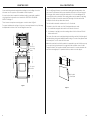
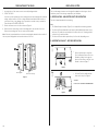
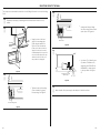
This microwave oven requires a mounting space on a wall as shown in Figure 1.
For proper installation and servicing, a 2-inch space is necessary between the top of the range
backsplash and the bottom of the Over the Range Microwave Oven.
Backsplash
36" or more
from cooking
surface
72" or more
from floor
15.5"
30"
12"
Minimum 2"
Figure 1
This Over the Range Microwave Oven should be mounted against and supported by a flat
vertical wall. The wall must be flat for proper installation. If the wall is not flat, use spacers to
fill in the gaps. Wall construction should be a minimum of 2" x 4" wood studding and 3/8"
or more thick dry wall or plaster/lath. The mounting surfaces must be capable of supporting
weight of 110 pounds—the oven and contents—AND the weight of all items which would
normally be stored in the top cabinet above the unit.
The unit should be attached to a minimum of one 2" x 4" wall stud.
To find the location of the studs, one of the following methods may be used:
A. Use a stud finder, a magnetic device which locates the nails in the stud.
B. Use a hammer to tap lightly across the mounting surface to find a solid sound. This will
indicate stud location.
The center of the stud can be located by probing the wall with a small nail to find the edges of
the stud and then placing a mark halfway between the edges. The center of any adjacent studs
will normally be 16" or 24" to either side of this mark.
Note: In the event that the unit will be unable to be supported by any stud, it will be necessary
to use special care in the placement of the toggle bolts and top cabinet screws. See Wall
Template for details. The top cabinet should be tested to ensure it is securely attached to the
wall. Place extra weight up to 110 pounds inside the top cabinet to test the support.
2"x 4"
Wood Studs
3/8" Dry Wall
or Plaster/lath
16" or 24"
Figure 2

EN 5
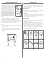
ELECTRICAL GROUNDING INSTRUCTIONS HOOD EXHAUST DUCT
This appliance must be grounded. This microwave oven is
equipped with a cord having a grounding wire with a grounding
plug. It must be plugged into a wall receptacle that is properly
installed and grounded in accordance with the National
Electrical Code and local codes and ordinances. In the event
of an electrical short circuit, grounding reduces risk of electric
shock by providing an escape wire for the electric current.
WARNING - IMPROPER USE OF THE GROUNDING PLUG CAN RESULT
IN A RISK OF ELECTRIC SHOCK. DO NOT USE AN EXTENSION CORD.
IF THE POWER SUPPLY CORD IS TOO SHORT, HAVE A QUALIFIED
ELECTRICIAN OR SERVICEPERSON INSTALL AN OUTLET NEAR THE
APPLIANCE.
The microwave oven is equipped with a 3-prong grounding plug. DO NOT UNDER ANY
CIRCUMSTANCES CUT OR REMOVE THE GROUNDING PIN FROM THE PLUG.
The Power Supply Cord and plug must be connected to a separate 120 Volt AC, 60 Hz, 15
Amp, or more branch circuit, single grounded receptacle. The receptacle should be located
inside the cabinet directly above the Microwave Oven mounting location.
Notes:
1. If you have any questions about the grounding or electrical instructions, consult a qualified
electrician or serviceperson.
2. Neither Fisher & Paykel nor the dealer can accept any liability for damage to the oven
or personal injury resulting from failure to observe the correct electrical connection
procedures.
Ground
Receptacle
Opening for
Power Cord
Figure 3
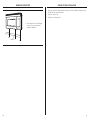
When the hood is vented to the outside, a hood exhaust duct is required. All ductwork must
be metal; absolutely do not use plastic duct. Check that all connections are made securely.
Please read the following carefully:
Exhaust connection
The hood exhaust has been designed to connect to a standard 3 1⁄4" x 10" rectangular duct. If
round duct is required, a rectangular-to-round adapter must be used.
Rear exhaust
If a rear or horizontal exhaust is to be used, care should be taken to align the exhaust with the
space between the studs, or wall should be prepared at the time it is constructed by leaving
enough space between wall studs to accommodate exhaust.
Maximum duct length
For satisfactory air movement, the total duct length of 3-1/4" x 10" rectangular or 6" diameter
round duct should not exceed 140 feet.
Elbows, adapters, wall, roof caps, etc. present additional resistance to air flow and are
equivalent to a section of straight duct which is longer than their actual physical size. When
calculating the total length, add the equivalent lengths of all transitions and adapters plus
the length of all straight duct sections. Figure 4 shows the approximate feet of equivalent
length of some typical ductwork parts. Use the values in parentheses for calculating air flow
resistance equivalent, which should total less than 140 feet.
90˚ Elbow
(10 ft. / 304.8 cm.)
45˚ Elbow
(5 ft. / 152.4 cm.)
Adaptor
(5 ft. / 152.4 cm.)
10˚ Wide elbow
(10 ft. / 304.8 cm.)
90˚ Elbow
(25 ft. / 762 cm.)
45˚ Elbow
(5 ft. / 152.4 cm.)
Wall cap
(40 ft. / 1219.2 cm.)
Roof cap
(24 ft. / 731.52 cm.)
Figure 4

6 EN
zPhillips screwdriver
zElectric drill
zScissors
zPencil
zTape
zMeasure tape
z1 1⁄2" wood bit or metal hole cutter (if metal cabinet is used)
z1⁄2", 5⁄8" and 3⁄32" drill bits
zSaw to cut exhaust opening (if needed)
zProtective drop cloth for product and range—you may also use carton for protection
TOOLS RECOMMENDED FOR INSTALLATION INSTALLATION HARDWARE
The INSTALLATION HARDWARE (items 1-8) packed with the oven should contain the
following:
ITEM NAME QUANTITY PART CODE
1Wood Screw 5 x 30 mm 6 290109
2Toggle Bolt #10 - 24 x 50 mm 4290106
3Top Cabinet Screw 5 x 60 mm 2290108
4Flat Washer 30 mm diameter 2290107
5Grommet 1290105
6Tapping Screw 4 x 12 mm 4245657
7Exhaust Damper Assembly 1290046
8Mounting Deflector 1290122
1 5
6 7
2 3 4
8
Figure 5

EN 7
PREPARATION OF THE OVEN VENTILATION SYSTEM
1. Open the bottom of the carton, remove oven and all packing materials.
2. CHECK THE OVEN.
Check the oven for any damage, such as misaligned or bent door, damaged door seals and
sealing surfaces, broken or loose door hinges and latches and dents inside the cavity or
on the door. If there is any damage, do not operate the oven and contact your dealer or
Fisher & Paykel AUTHORIZED SERVICER.
3. Rest the microwave oven on its side as shown in Figure 6.
4. Remove the two screws which secure the mounting plate to the rear side of the oven.
Remove the mounting plate. The two screws can be discarded.
Note: If the unit you purchased does not have the mounting plate attached to the rear side of
the oven, please disregard this section and continue to Section 8.
Mounting plate Grease filter openings
Figure 6
This Over-the-range microwave oven is designed for adaptation to three types of hood
ventilation systems. Select the type required for your installation.
A. RECIRCULATING - NON-VENTED, DUCTLESS OPERATION
The unit is shipped assembled for recirculating.
Note:
1. The Exhaust Damper Assembly (Figure 11) is not required for recirculating operation.
2. The Charcoal Filter provided with the unit must be installed behind the exhaust louver
before use. For instructions on installation of the filter, refer to the "Cleaning and Care"
section in the Use and Care Guide.
3. The Charcoal Filter should be replaced every 6 to 12 months, depending on use.
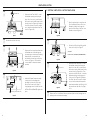
B. HORIZONTAL EXHAUST - OUTSIDE VENTILATION
Step
1
Figure 7
zRemove and save the 4 screws from
Fan Cover Bracket. Remove Fan Cover
Bracket by sliding it in the opposite
direction of the arrow on the Fan Cover
Bracket, as shown in Figure 7.
Step
2
Figure 8
zLift Hood Fan Unit carefully and slip
wires out of cavity. See Figure 8.
CAUTION:
DO NOT PULL OR STRETCH BLOWER WIRING.

8 EN
VENTILATION SYSTEM
Step
3(A) Rotate 180˚
(B)
Figure 9
zRotate the Hood Fan Unit 180˚ so that
the fan blade openings are facing the
back of the oven. Note, you will need to
lift the wire over the hood fan unit so the
wire will clear. See Figure 9 (A). Replace
Hood Fan Unit into the oven. Be careful
not to pinch the wire and the Hood Fan
Unit. See Figure 9 (B).
Step
4Put the wire back into the cavity.
Step
5
Wire Box
Figure 10
zReplace the fan cover bracket. Make sure
the fan blades are visible through the
rear openings in oven before proceeding.
Attach the fan cover bracket to the
unit with the 4 screws removed in step
1 above. See Figure 10. The hood fan
is now rotated for horizontal exhaust
operation.
Step
6
Mounting Plate (back side)
Figure 11
zAttach the Exhaust Damper Assembly
to the back of the mounting plate
by sliding it into the slits in the same
direction as the arrow. See Figure 11.
Using tapping screw 4 x 12 mm from the
INSTALLATION HARDWARE, tighten into
place.
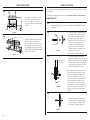
C. VERTICAL VENTILATION - OUTSIDE VENTILATION
Step
1Fan Cover Bracket
Figure 12
zRemove and save the 4 screws from the
Fan Cover Bracket. Remove Fan Cover
Bracket by sliding it in the opposite
direction of the arrow on the Fan Cover
Bracket as shown in Figure 12.
Step
2
Figure 13
zLift the Hood Fan Unit carefully and slip
wires out of cavity. See Figure 13.
CAUTION:
DO NOT PULL OR STRETCH BLOWER WIRING
Step
3(A) Rotate 180˚
(C)
(B)
Figure 14
zRotate the Hood Fan Unit 180˚ so that
the fan blade openings are facing the
back of the oven. Note, you will need to
lift the wire over the hood fan unit so the
wire will clear. See Figure 14 (A). Then
rotate the Hood Fan Unit 90˚ so that the
fan blade openings are facing the top
of the oven. See Figure 14 (B). Replace
Hood Fan Unit into the oven. Be careful
not to pinch the lead wire between the
inner bracket and the Hood Fan Unit. Put
the lead wire into Wire Box. See Figure
14 (C).
Step
4Replace the Fan Cover Bracket. Make sure the fan blades are visible through the top
openings in the oven before proceeding.

8 EN
VENTILATION SYSTEM
Step
3(A) Rotate 180˚
(B)
Figure 9
zRotate the Hood Fan Unit 180˚ so that
the fan blade openings are facing the
back of the oven. Note, you will need to
lift the wire over the hood fan unit so the
wire will clear. See Figure 9 (A). Replace
Hood Fan Unit into the oven. Be careful
not to pinch the wire and the Hood Fan
Unit. See Figure 9 (B).
Step
4Put the wire back into the cavity.
Step
5
Wire Box
Figure 10
zReplace the fan cover bracket. Make sure
the fan blades are visible through the
rear openings in oven before proceeding.
Attach the fan cover bracket to the
unit with the 4 screws removed in step
1 above. See Figure 10. The hood fan
is now rotated for horizontal exhaust
operation.
Step
6
Mounting Plate (back side)
Figure 11
zAttach the Exhaust Damper Assembly
to the back of the mounting plate
by sliding it into the slits in the same
direction as the arrow. See Figure 11.
Using tapping screw 4 x 12 mm from the
INSTALLATION HARDWARE, tighten into
place.
C. VERTICAL VENTILATION - OUTSIDE VENTILATION
Step
1Fan Cover Bracket
Figure 12
zRemove and save the 4 screws from the
Fan Cover Bracket. Remove Fan Cover
Bracket by sliding it in the opposite
direction of the arrow on the Fan Cover
Bracket as shown in Figure 12.
Step
2
Figure 13
zLift the Hood Fan Unit carefully and slip
wires out of cavity. See Figure 13.
CAUTION:
DO NOT PULL OR STRETCH BLOWER WIRING
Step
3(A) Rotate 180˚
(C)
(B)
Figure 14
zRotate the Hood Fan Unit 180˚ so that
the fan blade openings are facing the
back of the oven. Note, you will need to
lift the wire over the hood fan unit so the
wire will clear. See Figure 14 (A). Then
rotate the Hood Fan Unit 90˚ so that the
fan blade openings are facing the top
of the oven. See Figure 14 (B). Replace
Hood Fan Unit into the oven. Be careful
not to pinch the lead wire between the
inner bracket and the Hood Fan Unit. Put
the lead wire into Wire Box. See Figure
14 (C).
Step
4Replace the Fan Cover Bracket. Make sure the fan blades are visible through the top
openings in the oven before proceeding.
EN 9
VENTILATION SYSTEM
Step
5
Wire Box
Figure 15
zAttach the Fan Cover Bracket to unit
with the 4 screws removed in step 1
above. See Figure 15. The Hood Fan
Unit is now rotated for vertical exhaust
operation.
Step
6Exhaust Damper Assembly
Figure 16
zAttach the Exhaust Damper Assembly
to the fan cover on the top of the
outercase cabinet by sliding it into the
slits in the same direction as the arrow.
Use 1 Tapping Screw 4 x 12 mm from the
INSTALLATION HARDWARE and tighten
into place. See Figure 16.
OVEN INSTALLATION
This oven cannot be properly installed without referring to the mounting instructions found on
both templates.
Read and follow mounting information on both TOP CABINET TEMPLATE and WALL TEMPLATE.
MOUNTING PLATE
Step
1zSeparate 4 Toggle Bolts 2, packed in the INSTALLATION HARDWARE, from the
Toggle Nuts.
Step
2
Mounting Plate
Figure 17
zUse Wood Screws 1 to attach Mounting
Plate to the stud or studs. Use Toggle
Bolts to attach Mounting Plate through
the holes at A, B, C and D; UNLESS
THOSE HOLES ARE LOCATED ON THE
STUD. Insert one Toggle Bolt into A,
B, C and D where appropriate (these
correspond to the holes of the Wall
Template) and put the Toggle Nuts onto
the Toggle Bolts. Figure 17.
Refer to instructions in Wall Template.
Step
3
Wall
Space more than
wall thickness
Figure 18
zPosition the Mounting Plate with the
Toggle Bolts attached at the wall location
and insert Toggle Nuts and Bolts through
the holes in the wall with the Toggle Nuts
closed. Figure 18. Use Wood Screws 1 to
attach the Mounting Plate to studs.
Note: Before insertion, be sure you leave a
space more than the thickness of the wall
between the Mounting Plate and the end
of each of the Toggle Nuts (in the closed
position). If you do not leave enough space,
the Toggle Nut will not be able to open
on the other side of the wall. Also, once a
Toggle Nut opens, it cannot be withdrawn
from the hole; therefore make sure all of the
Toggles are in the correct position before
insertion.
Step
4
Figure 19
zAlign the Mounting Plate carefully and
hold in position while tightening Toggle
Bolts. Pull Toggle Bolt toward you and
turn clockwise to tighten. Figure 19.

10 EN
MOUNTING OVEN TO THE WALL
Two people are recommended to attach the Over the Range Microwave Oven to the Mounting
Plate.
Step
1Thread the power supply cord through the hole made in the bottom of the top
cabinet.
Step
2
Figure 20
zHang the oven on the lower
edge of the mounting plate.
Rotate the unit upward. See
Figure 20. Take care that the
power cord is able to clear the
edge of the hole as the oven is
rotated upward. (In the case of a
non-recessed bottom in the top
cabinet, the hole for the cord
may need to be enlarged.)
Step
3
Unit mounting screw
Figure 21
zTighten the two unit mounting
screws located in the grease
filter openings. See Figure 21.
Step
4
Grease filter
Figure 22
zInstall grease filters by fitting
into the opening. Push back and
up into place. See Figure 22.
Step
5
Grommet (for metal
cabinet only) (D) (E)
Figure 23
zUse the two Top Cabinet Screws
(D) and two Flat Washers (E),
supplied in the INSTALLATION
HARDWARE, to attach the unit
to the top cabinet. See Figure
23.
Step
6Make a bundle of the power supply cord and place it inside the cabinet.

EN 11
MOUNTING DEFLECTOR CHECKLIST FOR INSTALLATION
Deflector
zSecure the deflector with 3 Tapping
screws 4 x 12 mm, packed in the
Installation Hardware.
1. Make sure the unit has been installed according to all of the Installation Instructions and
the Wall and Top Cabinet Templates.
2. Plug in the power cord.
3. Keep the use and care guide.

243710E 11.21
TINSEB515MRR5
FISHERPAYKEL.COM
© Fisher & Paykel Appliances 2021. All rights reserved.
The models shown in this guide may not be available in all markets
and are subject to change at any time.
The product specifications in this guide apply to the specific products and
models described at the date of issue. Under our policy of continuous product
improvement, these specifications may change at any time.
For current details about model and specification availability in your country,
please go to our website or contact your local Fisher&Paykel dealer.
© Fisher&Paykel Appliances 2021. Tous droits réservés.
Les modèles illustrés dans ce guide peuvent ne pas être disponibles
dans tous les pays et sont sujets à modifications sans préavis.
Les caractéristiques de produit présentées dans ce guide s’appliquent aux
modèles et produits spécifiques qui y sont décrits à la date de publication.
Dans le cadre de notre politique d’amélioration en permanence de nos produits,
ces caractéristiques peuvent être modifiées à tout moment.
Pour les plus récentes informations sur la disponibilité des modèles
et des caractéristiques dans votre pays, veuillez visiter notre site Web ou
contacter votre détaillant Fisher&Paykel local.
-
 1
1
-
 2
2
-
 3
3
-
 4
4
-
 5
5
-
 6
6
-
 7
7
-
 8
8
-
 9
9
-
 10
10
-
 11
11
-
 12
12


Fisher & Paykel CMOH-30SS-2Y 30 Inch Over the Range Microwave Oven Guide d'installation
- Catégorie
- Hottes
- Taper
- Guide d'installation
- Ce manuel convient également à