
Contents
B21
INSTALLATION MANUAL
English
Svensk
a
Norsk
Dansk
Suomi
Deutsch
Nederlands
F
rançais
Español
Italiano
Português
Polski
Česky
Pyccкий
ﺔﻴﺑﺮﻌﻟا
Confi guration
Declaration of conformit
y
Installation guide

1
EN
B21
INSTALLATION MANUAL
Contents
Disclaimer ......................................................................................... 2
Copyright........................................................................................... 2
Trademark......................................................................................... 2
Introduction ....................................................................................... 3
Product Overview.............................................................................. 3
Installation ......................................................................................... 7
Installation Requirements.................................................................. 8
Troubleshooting ................................................................................ 8
Configuration..................................................................................... 9
Service and Maintenance.................................................................. 9
B21_install.book Page 1 Thursday, May 30, 2013 4:29 PM

2
Disclaimer
The information in this document is subject to change without notice
and should not be construed as a commitment by ABB AB. ABB AB as-
sumes no responsibility for any errors that may appear in this docu-
ment.
In no event shall ABB AB be liable for direct, indirect, special, incidental
or consequential damages of any nature or kind arising from the use of
this document, nor shall ABB AB be liable for incidental or consequen-
tial damages arising from use of any software or hardware described in
this document.
Copyright
This document and parts thereof must not be reproduced or copied
without written permission from ABB AB, and the contents thereof must
not be imparted to a third party nor used for any unauthorized purpose.
The software or hardware described in this document is furnished un-
der a license and may be used, copied, or disclosed only in accordance
with the terms of such license.
© Copyright 2013 ABB AB. All rights reserved.
Trademark
ABB AB is a registered trademark of the ABB Group. All other brand or
product names mentioned in this document may be trademarks or reg-
istered trademarks of their respective holders.
B21_install.book Page 2 Thursday, May 30, 2013 4:29 PM

3
EN
EN
Introduction
The B21 meter is a direct connected electricity meter for DIN-rail
mounting in distribution boards or small enclosures.
Read the information in this manual carefully before you install the
equipment.
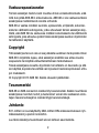
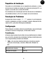
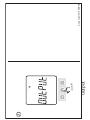
Product Overview
2
2
2
9
2
2
2
1
1
1
5
8
8
67
13
12
10
11
3
4
B21_install.book Page 3 Thursday, May 30, 2013 4:29 PM

4
Part Description
1 Terminal block
2 Sealing point
3 Product data
4 LED, flashes in proportion to the energy measured
5 Set button
6 OK/Exit button
7 Down/Up button
8 Sealable terminal cover
9 Terminal for communication connection
10 Terminal for I/O connection
11 Display
12 Optical communication interface
13 Sealing label
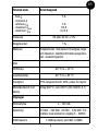
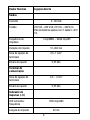
Tech. Data
Voltage
Voltage 220 - 240 V (-20% to +15%)
B21_install.book Page 4 Thursday, May 30, 2013 4:29 PM

5
EN
EN
Terminal wire area
Tightening torque
1 - 25 mm²
3.0 Nm
Current
- base
I
b
- reference
I
ref
- maximum
I
max
- minimum
I
min
5 A
5 A
65 A
0.25 A
Frequency 50 or 60 Hz ± 5%
Accuracy 1%
Material Polycarbonate in transparent front glass.
Glass reinforced polycarbonate in bottom
case and upper case. Polycarbonate in ter-
minal cover
Operating temp. -40 °C to +70 °C
Storage temp. -40 °C to +85 °C
Humidity 75% yearly average, 95% on 30 days/year
Resistance to heat Terminal 960°C, cover 650°C (IEC 60695-
2-1)
Outputs
Current 2 - 100 mA
Tech. Data
B21_install.book Page 5 Thursday, May 30, 2013 4:29 PM

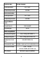
6
Voltage 24 VAC - 240 VAC, 24 VDC - 240 VDC. For
meters with only 1 output 5 - 40 VDC.
Pulse frequency 1-9999 pulse(s) per Wh, kWh or MWh
Pulse length 10 - 990 ms
Terminal wire area 0.5 - 1 mm²
Tightening torque 0.25 Nm
Comm. terminal
Terminal wire area 0.5 - 1 mm²
Tightening torque 0.25 Nm
Pulse indicator
Pulse frequency 1000 imp/kWh
Pulse length 40 ms
EMC
Impulse voltage test 6 kV 1.2/50μs (IEC 60060-1)
Surge voltage test 4 kV 1.2/50μs (IEC 61000-4-5)
Fast trans. burn test 4 kV ( IEC 61000-4-4 )
Immunity HF-fields 80 MHz - 2 GHz at 10 V/m (IEC61000-4-3)
Tech. Data
B21_install.book Page 6 Thursday, May 30, 2013 4:29 PM

7
EN
EN
Installation
For information about how to mount and install the equipment, follow
the instructions in the Installation Guide at the end of this manual.
E Warning – Working with high voltage is potentially lethal. Per-
sons subjected to high voltage may suffer cardiac arrest, burn
injuries, or other severe injuries. To avoid such injuries, make
sure to disconnect the power supply before you start the instal-
lation.
Electrical equipment should only be installed, accessed, ser-
viced and maintained by qualified electrical personnel.
E Warning – For safety reasons it is recommended that the
equipment is installed in a way that makes it impossible to
reach or touch the terminal blocks by accident.
Immunity conducted 2kHz - 150kHz
150kHz – 80MHz ( IEC 61000-4-6 )
RF Emission EN 55022, class B (CISPR22)
ESD 15 kV ( IEC 61000-4-2 )
Standards IEC 62052-11, IEC 62053-21 class 1 & 2,
IEX 62053-23 class 2, IEC 62054-21, GB/T
17215.211-2006, GB/T 17215.321-2008
class 1 & 2, GB/T 17215.322-2008 class
0.5 S, GB 4208-2008, EN 50470-1, EN
50470-3 category A, B
Tech. Data
B21_install.book Page 7 Thursday, May 30, 2013 4:29 PM

8
The best way to make a safe installation is to install the unit in
an enclosure. Further, access to the equipment should be lim-
ited through use of lock and key, controlled by qualified electri-
cal personnel.
W Warning – The meters must always be protected by fuses on
the incoming side.
Do not operate the equipment outside the specified technical
data.
Installation Requirements
To comply with the protection requirements the meter must be
mounted in protection class IP 51 enclosures, or better, according to
IEC 60259.
Meters with wireless communication should not be installed closer
than 20 cm from people.
Troubleshooting
If any of the following icons W VC appear in the display after the
installation has been completed and power has been connected to the
meter, refer to the B21 User Manual for detailed information.
B21_install.book Page 8 Thursday, May 30, 2013 4:29 PM

9
EN
EN
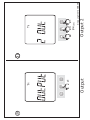
Configuration
To configure the meter and change the default settings, follow the in-
structions in the Configuration Guide at the end of this manual.
Default Settings
The following table lists the default settings of the meter that normally
needs to be changed. Check the settings to see if any of them needs to
be changed.
N Note – For all other settings, including communication default
settings, refer to the B21 User Manual.
Service and Maintenance
The meter contains no parts that can be repaired or exchanged. A bro-
ken meter must be replaced.
If the meter needs to be cleaned, use a lightly moistened cloth and a
mild detergent to wipe it.
C Caution – Be careful that no liquid gets into the meter since it
may damage the equipment.
Pulse frequency 100 imp/kWh
Pulse length 100 ms
B21_install.book Page 9 Thursday, May 30, 2013 4:29 PM

10
B21_install.book Page 10 Thursday, May 30, 2013 4:29 PM

1
SV
B21
INSTALLATIONSMANUAL
Contents
Friskrivning........................................................................................ 2
Copyright........................................................................................... 2
Varumärke......................................................................................... 2
Introduktion ....................................................................................... 3
Produktöversikt ................................................................................. 3
Installation ......................................................................................... 7
Installationskrav ................................................................................ 8
Felsökning......................................................................................... 8
Konfigurering..................................................................................... 9
Service och underhåll........................................................................ 9
B21_install.book Page 1 Thursday, May 30, 2013 4:29 PM

2
Friskrivning
Informationen i detta dokument är föremål för ändringar utan föregå-
ende meddelande och ska inte betraktas som ett åtagande från ABB
AB. ABB AB tar inte något ansvar för fel som kan uppträda i detta doku-
ment.
I inget fall ska ABB AB vara ansvarig för direkta, indirekta, speciella,
oförutsedda eller följdskador av något slag eller typ som uppkommer
vid användning av detta dokument, ej heller ska ABB AB vara ansvarig
för oförutsedda eller följdskador som uppkommer vid användning av
mjukvara eller hårdvara som beskrivs i detta dokument.
Copyright
Detta dokument och delar därav får inte reproduceras eller kopieras
utan skriftligt tillstånd från ABB AB, och innehållet däri får inte vidare-
befordras till tredje part eller användas för något icke godkänt syfte.
Den mjukvara eller hårdvara som beskrivs i detta dokument tillhanda-
hålls under licens och får endast användas, kopieras eller röjas i enlig-
het med villkoren i licensen.
© Copyright 2013 ABB AB. Alla rättigheter förbehållna.
Varumärke
ABB AB är ett registrerat varumärke tillhörande ABB-koncernen. Alla
övriga märkes- eller produktnamn som nämns i detta dokument kan
vara varumärken eller registrerade varumärken som tillhör respektive
innehavare.
B21_install.book Page 2 Thursday, May 30, 2013 4:29 PM

3
SV
SV
Introduktion
B21-mätaren är en direktansluten elektricitetsmätare för montering på
DIN-skena i undercentraler eller mindre skåp.
Läs informationen i denna manual noggrant innan du installerar utrust-
ningen.
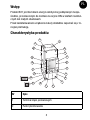
Produktöversikt
Del Beskrivning
1 Anslutningsplint.
2 Plomberingspunkt.
3 Produktdata.
2
2
2
9
2
2
2
1
1
1
5
8
8
67
13
12
10
11
3
4
B21_install.book Page 3 Thursday, May 30, 2013 4:29 PM

4
4 Lysdiod, blinkar i förhållande till uppmätt energi.
5 SET-knapp.
6 OK/Tillbaka-knapp
7 Upp/Ned-knapp
8 Plomberingsbart täcklock
9 Uttag för kommunikationsanslutning.
10 Uttag för I/O-anslutning.
11 Display.
12 IR-gränssnitt.
13 Plombering.
Teknisk data Direktkopplad
Spänning
Spänning 220 - 240 V (-20% - +15%)
Kabeldimension
Åtdragningsmoment
1 - 25 mm²
3.0 Nm
Strömstyrka
Del Beskrivning
B21_install.book Page 4 Thursday, May 30, 2013 4:29 PM

5
SV
SV
- bas
I
b
- nominell
I
n
- referens
I
ref
- maximum
I
max
- minimum
I
min
5 A
5 A
65 A
0.25 A
Frekvens 50 eller 60 Hz ± 5%
Noggrannhet 1%
Material Polykarbonat i transparent frontglas, hölje
och täcklock. Glasfiberförstärkt polykarbo-
nat i anslutningsplint.
Vikt
Drifttemp. -40 °C to +70 °C
Lagringstemp. -40 °C to +85 °C
Fuktighet 75% årsgenomsnitt, 95% under 30 dgr/år
Motståndskraft mot
värme
Uttag 960°C, lock 650°C (IEC 60695-2-1)
Utgångar
Strömstyrka 2 - 100 mA
Spänning 24 VAC - 240 VAC, 24 VDC - 240 VDC. För
mätare med endast en utgång 5 - 40VDC.
Pulsfrekvens 1-9999 pulse(s) per kWh or MWh
Teknisk data Direktkopplad
B21_install.book Page 5 Thursday, May 30, 2013 4:29 PM

6
Pulslängd 10 - 990 ms
Kabeldimension 0.5 - 1 mm²
Åtdragningsmoment 0.25 Nm
Komm.uttag
Kabeldimension 0.5 - 1 mm²
Åtdragningsmoment 0.25 Nm
Pulsindikator
(lysdiod)
Röd lysdiod/frekv. 100 imp/kWh
Pulsbredd 40 ms
EMC-kompatibilitet
Pulsspänningstest 6 kV 1.2/50μs (IEC 60060-1)
Överspänningstest 4 kV 1.2/50μs (IEC 61000-4-5)
Snabba transienter
och pulsskurar
4 kV ( IEC 61000-4-4 )
Immunitet HF-fält 80 MHz - 2 GHz at 10 V/m (IEC61000-4-3)
Immunitet
ledningsburen
2 kHz - 150 KHz
150 kHz – 80 MHz ( IEC 61000-4-6 )
Teknisk data Direktkopplad
B21_install.book Page 6 Thursday, May 30, 2013 4:29 PM

7
SV
SV
Installation
För information om hur utrustningen monteras och installeras, följ in-
struktionerna i Installationsguiden i slutet av denna manual.
E Varning – Arbete med högspänning är potentiellt livsfarligt.
Personer som utsätts för högspänning kan utsättas för hjärtstil-
lestånd, brännskador eller andra allvarliga skador. Se till att
koppla bort strömtillförseln innan du startar installationen, för
att undvika sådana skador.
Elektrisk utrustning får endast installeras, vara tillgänglig för,
skötas och underhållas av kvalificerad elektriker.
E Varning – Av säkerhetsskäl rekommenderar vi att utrustningen
installeras på ett sätt som gör det omöjligt att nå eller vidröra
anslutningsplintarna av misstag.
Bästa sättet att göra en säker installation är att installera enhe-
ten i ett skåp. Dessutom ska åtkomst till utrustningen begrän-
RF-emission EN 55022, class B (CISPR22)
ESD 15 kV ( IEC 61000-4-2 )
Standarder IEC 62052-11, IEC 62053-21 klass 1 & 2,
IEX 62053-23 klass 2, IEC 62054-21, GB/T
17215.211-2006, GB/T 17215.321-2008
klass 1 & 2, GB/T 17215.322-2008 klass
0.5 S, GB 4208-2008, EN 50470-1, EN
50470-3 kategori A, B
Teknisk data Direktkopplad
B21_install.book Page 7 Thursday, May 30, 2013 4:29 PM

8
sas genom användning av lås med nyckel, kontrollerat av
kvalificerad elektriker.
W Varning – Mätarna måste alltid skyddas med säkringar på in-
kommande sida.
Använd inte utrustningen utanför specificerade tekniska data.
Installationskrav
För att uppfylla skyddskraven måste mätaren vara monterade i skåp av
skyddsklass IP 51, eller bättre, enligt IEC 60259.
Mätare med trådlös kommunikation får inte installeras närmare än
20 cm från människor.
Felsökning
Om någon av följande ikoner,W VC, visas i displayen efter att in-
stallationen har slutförts och strömmen har anslutits till mätaren, se
B21 Användarmanual för detaljerad information.
Konfigurering
Vid konfigurering av mätaren och ändring av standardinställningar, följ
instruktionerna i Konfigurationsguiden i slutet av denna manual.
Standardinställningar
Följande tabell anger standardinställningar för mätaren vilka normalt
behöver ändras. Kontrollera inställningarna för att se om någon av dem
behöver ändras.
N Obs – För alla övriga inställningar, inklusive standardinställ-
ningar för kommunikation, se B21 Användarmanual.
B21_install.book Page 8 Thursday, May 30, 2013 4:29 PM

9
SV
SV
Service och underhåll
Mätarna innehåller inga delar som kan repareras eller bytas. En trasig
mätare måste bytas ut.
Om mätaren behöver rengöras, ska du torka av den med en lätt fuktad
trasa och ett milt rengöringsmedel.
C Försiktighet – Var försiktig så att ingen vätska kommer in i mä-
taren eftersom det kan skada utrustningen.
Pulsfrekvens 100
Pulslängd 100 ms
B21_install.book Page 9 Thursday, May 30, 2013 4:29 PM
La page est en cours de chargement...
La page est en cours de chargement...
La page est en cours de chargement...
La page est en cours de chargement...
La page est en cours de chargement...
La page est en cours de chargement...
La page est en cours de chargement...
La page est en cours de chargement...
La page est en cours de chargement...
La page est en cours de chargement...
La page est en cours de chargement...
La page est en cours de chargement...
La page est en cours de chargement...
La page est en cours de chargement...
La page est en cours de chargement...
La page est en cours de chargement...
La page est en cours de chargement...
La page est en cours de chargement...
La page est en cours de chargement...
La page est en cours de chargement...
La page est en cours de chargement...
La page est en cours de chargement...
La page est en cours de chargement...
La page est en cours de chargement...
La page est en cours de chargement...
La page est en cours de chargement...
La page est en cours de chargement...
La page est en cours de chargement...
La page est en cours de chargement...
La page est en cours de chargement...
La page est en cours de chargement...
La page est en cours de chargement...
La page est en cours de chargement...
La page est en cours de chargement...
La page est en cours de chargement...
La page est en cours de chargement...
La page est en cours de chargement...
La page est en cours de chargement...
La page est en cours de chargement...
La page est en cours de chargement...
La page est en cours de chargement...
La page est en cours de chargement...
La page est en cours de chargement...
La page est en cours de chargement...
La page est en cours de chargement...
La page est en cours de chargement...
La page est en cours de chargement...
La page est en cours de chargement...
La page est en cours de chargement...
La page est en cours de chargement...
La page est en cours de chargement...
La page est en cours de chargement...
La page est en cours de chargement...
La page est en cours de chargement...
La page est en cours de chargement...
La page est en cours de chargement...
La page est en cours de chargement...
La page est en cours de chargement...
La page est en cours de chargement...
La page est en cours de chargement...
La page est en cours de chargement...
La page est en cours de chargement...
La page est en cours de chargement...
La page est en cours de chargement...
La page est en cours de chargement...
La page est en cours de chargement...
La page est en cours de chargement...
La page est en cours de chargement...
La page est en cours de chargement...
La page est en cours de chargement...
La page est en cours de chargement...
La page est en cours de chargement...
La page est en cours de chargement...
La page est en cours de chargement...
La page est en cours de chargement...
La page est en cours de chargement...
La page est en cours de chargement...
La page est en cours de chargement...
La page est en cours de chargement...
La page est en cours de chargement...
La page est en cours de chargement...
La page est en cours de chargement...
La page est en cours de chargement...
La page est en cours de chargement...
La page est en cours de chargement...
La page est en cours de chargement...
La page est en cours de chargement...
La page est en cours de chargement...
La page est en cours de chargement...
La page est en cours de chargement...
La page est en cours de chargement...
La page est en cours de chargement...
La page est en cours de chargement...
La page est en cours de chargement...
La page est en cours de chargement...
La page est en cours de chargement...
La page est en cours de chargement...
La page est en cours de chargement...
La page est en cours de chargement...
La page est en cours de chargement...
La page est en cours de chargement...
La page est en cours de chargement...
La page est en cours de chargement...
La page est en cours de chargement...
La page est en cours de chargement...
La page est en cours de chargement...
La page est en cours de chargement...
La page est en cours de chargement...
La page est en cours de chargement...
La page est en cours de chargement...
La page est en cours de chargement...
La page est en cours de chargement...
La page est en cours de chargement...
La page est en cours de chargement...
La page est en cours de chargement...
La page est en cours de chargement...
La page est en cours de chargement...
La page est en cours de chargement...
La page est en cours de chargement...
La page est en cours de chargement...
La page est en cours de chargement...
La page est en cours de chargement...
La page est en cours de chargement...
La page est en cours de chargement...
La page est en cours de chargement...
La page est en cours de chargement...
La page est en cours de chargement...
La page est en cours de chargement...
La page est en cours de chargement...
La page est en cours de chargement...
La page est en cours de chargement...
La page est en cours de chargement...
La page est en cours de chargement...
La page est en cours de chargement...
La page est en cours de chargement...
La page est en cours de chargement...
La page est en cours de chargement...
La page est en cours de chargement...
La page est en cours de chargement...
La page est en cours de chargement...
La page est en cours de chargement...
La page est en cours de chargement...
La page est en cours de chargement...
La page est en cours de chargement...
La page est en cours de chargement...
La page est en cours de chargement...
La page est en cours de chargement...
La page est en cours de chargement...
La page est en cours de chargement...
La page est en cours de chargement...
La page est en cours de chargement...
La page est en cours de chargement...
La page est en cours de chargement...
La page est en cours de chargement...
La page est en cours de chargement...
La page est en cours de chargement...
La page est en cours de chargement...
La page est en cours de chargement...
La page est en cours de chargement...
La page est en cours de chargement...
La page est en cours de chargement...
-
 1
1
-
 2
2
-
 3
3
-
 4
4
-
 5
5
-
 6
6
-
 7
7
-
 8
8
-
 9
9
-
 10
10
-
 11
11
-
 12
12
-
 13
13
-
 14
14
-
 15
15
-
 16
16
-
 17
17
-
 18
18
-
 19
19
-
 20
20
-
 21
21
-
 22
22
-
 23
23
-
 24
24
-
 25
25
-
 26
26
-
 27
27
-
 28
28
-
 29
29
-
 30
30
-
 31
31
-
 32
32
-
 33
33
-
 34
34
-
 35
35
-
 36
36
-
 37
37
-
 38
38
-
 39
39
-
 40
40
-
 41
41
-
 42
42
-
 43
43
-
 44
44
-
 45
45
-
 46
46
-
 47
47
-
 48
48
-
 49
49
-
 50
50
-
 51
51
-
 52
52
-
 53
53
-
 54
54
-
 55
55
-
 56
56
-
 57
57
-
 58
58
-
 59
59
-
 60
60
-
 61
61
-
 62
62
-
 63
63
-
 64
64
-
 65
65
-
 66
66
-
 67
67
-
 68
68
-
 69
69
-
 70
70
-
 71
71
-
 72
72
-
 73
73
-
 74
74
-
 75
75
-
 76
76
-
 77
77
-
 78
78
-
 79
79
-
 80
80
-
 81
81
-
 82
82
-
 83
83
-
 84
84
-
 85
85
-
 86
86
-
 87
87
-
 88
88
-
 89
89
-
 90
90
-
 91
91
-
 92
92
-
 93
93
-
 94
94
-
 95
95
-
 96
96
-
 97
97
-
 98
98
-
 99
99
-
 100
100
-
 101
101
-
 102
102
-
 103
103
-
 104
104
-
 105
105
-
 106
106
-
 107
107
-
 108
108
-
 109
109
-
 110
110
-
 111
111
-
 112
112
-
 113
113
-
 114
114
-
 115
115
-
 116
116
-
 117
117
-
 118
118
-
 119
119
-
 120
120
-
 121
121
-
 122
122
-
 123
123
-
 124
124
-
 125
125
-
 126
126
-
 127
127
-
 128
128
-
 129
129
-
 130
130
-
 131
131
-
 132
132
-
 133
133
-
 134
134
-
 135
135
-
 136
136
-
 137
137
-
 138
138
-
 139
139
-
 140
140
-
 141
141
-
 142
142
-
 143
143
-
 144
144
-
 145
145
-
 146
146
-
 147
147
-
 148
148
-
 149
149
-
 150
150
-
 151
151
-
 152
152
-
 153
153
-
 154
154
-
 155
155
-
 156
156
-
 157
157
-
 158
158
-
 159
159
-
 160
160
-
 161
161
-
 162
162
-
 163
163
-
 164
164
-
 165
165
-
 166
166
-
 167
167
-
 168
168
-
 169
169
-
 170
170
-
 171
171
-
 172
172
-
 173
173
-
 174
174
-
 175
175
-
 176
176
-
 177
177
-
 178
178
-
 179
179
-
 180
180
-
 181
181


dans d''autres langues
- italiano: ABB B21 Guida d'installazione
- English: ABB B21 Installation guide
- español: ABB B21 Guía de instalación
- Deutsch: ABB B21 Installationsanleitung
- русский: ABB B21 Инструкция по установке
- Nederlands: ABB B21 Installatie gids
- português: ABB B21 Guia de instalação
- dansk: ABB B21 Installationsvejledning
- polski: ABB B21 Instrukcja instalacji
- čeština: ABB B21 instalační příručka
- svenska: ABB B21 Installationsguide
- suomi: ABB B21 Asennusohje
Documents connexes
Autres documents
-
Inspire 3276007487879 Clane Spotlight Manuel utilisateur
-
Bticino F21DM63N Mode d'emploi
-
-
Fantini Cosmi ECC15CA2 – ECC20CA2 Mode d'emploi
-
-
CARLO GAVAZZI EM110DINAV81XO1PFB Guide d'installation
-
CARLO GAVAZZI EM111DINAV81XO1PFA Guide d'installation
-