
ARMO
ARMO

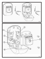
Fig. 1
Fig. 1

Fig. 3 Fig. 4
Fig. 5
Fig. 7
Fig. 6
Fig. 8

Fig. 10Fig. 9
Fig. 11 Fig. 12

2
ENGLISH
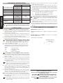
1. TECHNICAL SPECIFICATIONS
ARMO 24V ARMO 230V
Power supply voltage
24 Vdc
24 V~
115 - 230 V~
(+6% -10%)
Contacts max. Load 100 mA 15 A
Nr. of microswitches 22
Type of Contacts NC/NO - NC/NO NC/NO - NC/NO
IP Class 55 55
Lock
Standard DIN
18252
41,5 - 45 mm
Standard DIN
18252
41,5 - 45 mm
Release Travel 25 mm 25 mm
Installation On-wall On-wall
Do not remove the safety plug shown in Fig.11, before
this is expressly indicated in the installation procedu-
re.
2. INSTALLATION
To install the ARMO device, observe the following steps:
Position the device near the automated system to be
piloted/released. Take into consideration the overall
dimensions shown in Fig. 1;
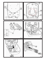
Fig. 3 shows the rear of the device, indicating the slot for
routing the electric cables ( ref. ) and the housing of
the traction cable for manual release ( ref. );
Use the device to mark the on-wall references of the
holes, as shown in Fig.4 ref. ;
Make sure that the hole for routing the electric cables
and the release cable, has a diameter of not less than
40 mm and is positioned as shown in Fig. 4 ref.
Secure the device on a wall;
Connect the electric cables coming from the auto-
mated system to the relevant terminal-boards of the
microswitches (Fig.5) according to the type of com-
mand:
NO = Normally OPEN
NC = Normally CLOSED
C = COMMON
rif. = EARTH cable fitting
It’s forbidden to use the ARMO as electric shunt box!
Fit the release cable, without a sheath, inside the hole as
shown in Fig. 6 ref. , crossing also over the tensioning
device ( ref. );
Before you tighten the release cable on the tensioning
device, take the device to the travel limit, as shown in
Fig. 6 ref. , turning the head of the adjusting screw with
a hexagon wrench;
Make sure that the door of the XK 21 device is kept
open by the red Locking Lever ref. d in Fig.2, before
tightening the cable on the tensioning device.
Using a pair of pincers, apply tension to the cable
WITHOUT RELEASING the connected OPERATOR, and
then tighten the release cable on the tensioning device
with the relevant screw;
Turning the head of the adjustment screw with a hexagon
wrench, move the tensioning device until you release the
operator, connected as shown in Fig. 7 ref. ;
Cut excess cable at the exit of the tensioning device;
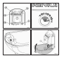
If it is not present, fit the lock, conforming to standard
DIN 18252 and its gasket on the front of the device as
shown in Fig. 8;
To facilitate fitting the lock, push down the top ends
of the levers activating the microswitches as shown
in Fig. 8 ref. .
1.
2.
3.
4.
5.
6.
7.
8.
9.
10.
11.
Fasten the lock, inserted as above, with the supplied
plate and screws ( Fig.8 );
Join the front part to the part secured to the wall, ti-
ghtening the four self-forming screws as shown in Fig. 9
ref. , take care when laying the cables coming from
the microswitches, as shown in Fig. 6 in order to avoid
any squeezing;
Check activation of the microswitches, turning the key
in the lock according to the diagram in Fig.10:
A = activation of microswitch ref. in Fig.2
B = activation of microswitch ref. in Fig.2
C = detachment of release lever
Check if position C corresponds to the disappearance
of the piston ref. in Fig.9, inside the body of the
device.
When you have checked the activation of the lock
release piston, remove the safety plug from the release
lever as shown in Fig. 11;
Close the device, first lifting the red Locking Lever, and
then the Release Lever to close the device as shown in
Fig. 12.
CE DECLARATION OF CONFORMITY
Manufacturer: GENIUS S.p.A.
Address: Via Padre Elzi, 32 - 24050 - Grassobbio- Bergamo
- ITALY
Declares that: Device ARMO is conforms to Low Voltage
Directive 2006/95/CE.
Grassobbio, 23 April 2008
Managing Director
D. Gianantoni
12.
13.
14.
15.
16.
Notes on reading the instruction
Read this installation manual to the full before you begin
installing the product.
The symbol
indicates notes that are important for
the safety of persons and for the good condition of the
automated system.
The symbol
draws your attention to the notes on the
characteristics and operation of the product.

Le descrizioni e le illustrazioni del presente manuale non sono impegnative. GENIUS si riserva il diritto, lasciando inal-
terate le caratteristiche essenziali dell’apparecchiatura, di apportare in qualunque momento e senza impegnarsi
ad aggiornare la presente pubblicazione, le modifiche che essa ritiene convenienti per miglioramenti tecnici o per
qualsiasi altra esigenza di carattere costruttivo o commerciale.
The descriptions and illustrations contained in the present manual are not binding. GENIUS reserves the right, whils
leaving the main features of the equipments unaltered, to undertake any modifications to holds necessary for either
technical or commercial reasons, at any time and without revising the present publication.
Les descriptions et les illustrations du présent manuel sont fournies à titre indicatif. GENIUS se réserve le droit d’apporter
à tout moment les modifications qu’elle jugera utiles sur ce produit tout en conservant les caractéristiques essentielles,
sans devoir pour autant mettre à jour cette publication .
Las descripciones y las ilustraciones de este manual no comportan compromiso alguno. GENIUS se reserva el de-
recho, dejando inmutadas las características esenciales de los aparatos, de aportar, en cualquier momento y sin
comprometerse a poner al día la presente publicación, todas las modificaciones que considere oportunas para el
perfeccionamiento técnico o para cualquier otro tipo de exigencia de carácter constructivo o comercial.
Timbro rivenditore: / Distributor’s stamp: / Timbre de l’agent: / Sello del revendedor: / Fachhändlerstempel: / Stem-
pel dealer:
Via Padre Elzi, 32
24050 - Grassobbio
BERGAMO-ITALY
tel. 0039.035.4242511
fax. 0039.035.4242600
www.geniusg.com
00058I0764 Rev.0
-
 1
1
-
 2
2
-
 3
3
-
 4
4
-
 5
5
-
 6
6


dans d''autres langues
- English: Genius ARMO Operating instructions
Documents connexes
-
Genius ARMO Mode d'emploi
-
-
Genius JA574 Use And Installation Instructions
-
Genius JA668 Mode d'emploi
-
-
-
-
-
-