Honeywell Home THX321WFS2001W Guide d'installation
- Catégorie
- Thermostats
- Taper
- Guide d'installation

Package Includes:
• T10 Pro Smart Thermostat
• UWP™ Mounting System
• Standard Installation Adapter (J-box
adapter)
• Decorative Cover Plate
• Screws and Anchors
• Thermostat literature
TH321WF2003W depicted.
T10 Pro Smart
Thermostat with
RedLINK™
THX321WFS20 01W
(Sensor included)
THX321WF2003W
(No sensor)
Programmable Thermostat
Professional Install Guide
Read before installing
33-00479EFS-05
Search for local rebates.
Honeywell Home thermostats
work with utility programs to
reward you for helping save
energy.
HoneywellHome.com/Rebates
Compatibility
• Compatible with most heating, cooling, and heat pump systems
• Required: 24 VAC power (“C” wire)
• Does not work with electric baseboard heat (120240V)
• Does not work with millivolt systems
• Android or iOS smartphone or tablet
Customer assistance
WEB honeywellhome.com
PHONE 18006333991

2
UWP Mounting System installation
1. Open package to find the UWP. See
Figure 1.
2. Position the UWP on the wall. Level and
mark hole positions. See Figure 2.
Drill holes at marked positions, and then
lightly tap supplied wall anchors into wall
using a hammer.
‒If your box contains red anchors, use
a 7/32” drill bit. If your box contains
yellow anchors, use a 3/16” drill bit.
3. Pull the door open and insert wires
through wiring hole of the UWP. See
Figure 3.
4. Place the UWP over the wall anchors.
Insert and tighten mounting screws
supplied with the UWP. Do not
overtighten. Tighten until the UWP no
longer moves. Close the door. See Figure
4.
1
2
3
4
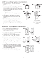
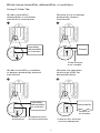
Optional Cover Plate installation
Use the Optional Cover Plate when:
• Mounting the thermostat to an
electrical junction box
• Or when you need to cover paint gap
from the old thermostat.
5. Separate the Junction Box Adapter
from the Cover Plate. See Figure 5.
6. Mount the Junction Box Adapter to
the wall or an electrical box using any
of the eight screw holes. Insert and
tighten mounting screws supplied with
Cover Plate Kit. Do not overtighten.
Make sure the Adapter Plate is level.
See Figure 6.
7. Attach the UWP by hanging it on the
top hook of the Junction Box Adapter
and then snapping the bottom of the
UWP in place. See Figure 7.
8. Snap the Cover Plate onto the
Junction Box Adapter. See Figure 8.
Use 3x supplied
screws (#8 11/2
for red anchors and
#6 11/2 for yellow
anchors)
Use 2x
supplied
screws
#6 5/8”
1/4” to 3/8”
1
2
3 4
1 2
3
4
8
7
6
5
M37809

3
Terminal designations
Conventional Systems Heat pump systems
Terminal Description Terminal Description
S/S Input for a wired indoor,
outdoor sensor S/S Input for a wired indoor,
outdoor sensor
Y Compressor Stage 1 Y Compressor Stage 1
Y2 Compressor Stage 2 Y2 Compressor Stage 2
G Fan Relay G Fan Relay
C24VAC Common wire from
secondary side of cooling
transformer (if 2 transformers) C24VAC Common wire from
secondary side of cooling
transformer
K* Connect to K on C-wire
adaptor K* Connect to K on C-wire
adaptor
U/U** Relay for humidifier,
dehumidifier, or ventilator U/U** Relay for humidifier,
dehumidifier, or ventilator
A L/A Connect to compressor
monitor
W Heat Stage 1 O/B Changeover valve for heat
pumps
W2 Heat Stage 2 Aux Backup Heat
E Emergency Heat
R 24 VAC Heating transformer R 24 VAC Heating transformer
Rc 24 VAC Cooling transformer Rc 24 VAC Cooling transformer
* The THP9045A1098 C-wire adaptor is used on heat/cool systems when you only have four wires at
the thermostat and you need a fifth wire for a common wire. Use the K terminal in place of the Y and
G terminals on conventional or heat pump systems to provide control of the fan and the compressor
through a single wire—the unused wire then becomes your common wire. See THP9045 instructions
for more information.
** See note on Wiring U terminals on the following page.
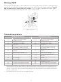
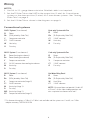
Wiring UWP
Push down on the tabs to put the wires into the inner holes of their corresponding
termi nals on the UWP (one wire per terminal) until they are firmly in place. Gently
tug on the wires to verify they are secure. If you need to release the wires again,
push down the terminal tabs on the sides of the UWP.
This wiring is just an example,
yours may vary.

4
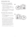
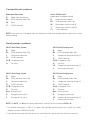
Setting Slider Tabs
Set R Slider Tab, see Figure 9.
• Use built-in jumper (R Slider Tab)
to differentiate between one or two
transformer systems.
• If there is only one R wire, and it is
connected to the R, Rc, or RH terminal
on the old thermostat, set the slider to
the up position (1 wire).
• If there is one wire connected to the R
terminal and one wire connected to the
Rc terminal, set the slider to the down
position (2 wires).
Set U Slider Tab, see Figure 10.
• Use built-in jumper (U Slider Tab) for
IAQ device.
• When the U Slider Tab is in the down
position (2 wires) the U contacts are a
dry set of contacts.
• If your IAQ device is powered by the
cooling transformer, move the U Slider
Tab to the up position (1 wire). When
this is done, the lower U terminal is
internally jumped to the Rc terminal.
In this application, you would hook
up one wire from your IAQ device to
the upper U terminal and the other
to the common side of the cooling
transformer. The 1 wire setting is most
commonly used when using a fresh
air damper for ventilation or using low
speed fan for dehumidification.
• See wiring examples on the next page.
10
9

5
Whole house humidifier, dehumidifier, or ventilator
Using U Slider Tab
Wired to humidifier,
dehumidifier or ventilator
with built-in transformer.
Wired to fresh air damper
powered by furnace
transformer.
11 12
Damper
C from furnace
or air-handler
Humidifier,
dehumidifier,
or ventilator
Wired to humidifier, ventilator,
or damper powered by external
transformer
Wired to low speed fan
terminal on HVAC for
dehumidification
13 14
Humidifier,
dehumidifier,
or ventilator
R from 24 volt
transformer
C (common) from
24 volt transformer
Dehumidifier*
Furnace or
air-handler
* Label for this terminal
varies by equipment

6
* This thermostat requires a C-Wire. If a C-Wire is not available and the system uses Y and G, use C-Wire
adapter accessory THP9045A1098.
Wiring
1H/1C System (1 transformer)
R Power
Rc [R+Rc joined by Slider Tab]
Y Compressor contactor
C* 24VAC common
W Heat relay
G Fan relay
NOTES:
1. Use 18 to 22 gauge thermostat wire. Shielded cable is not required.
2. Set the R Slider Tab on the UWP to the up position (1 wire) for 1 transformer
systems or the down position (2 wires) for 2 transformer systems. See "Setting
Slider Tabs" on page 4.
3. Set the U Slider Tab as shown in the diagrams on page 4.
Conventional systems
1H/1C System (2 transformers)
R Power (heating transformer)
Rc Power (cooling transformer)
Y Compressor contactor
C* 24 VAC common from cooling transformer
W Heat relay
G Fan relay
2H/2C System (1 transformer)
R Power
Rc [R+Rc joined by Slider Tab]
Y Compressor contactor (stage 1)
C* 24VAC common
W Heat relay (stage 1)
G Fan relay
W2 Heat relay (stage 2)
Y2 Compressor contactor (stage 2)
Heat-only System with Fan
R Power
Rc [R+Rc joined by Slider Tab]
C* 24VAC common
W Heat relay
G Fan relay
Cool-only System with Fan
R Power
Rc [R+Rc joined by Slider Tab]
Y Compressor contactor
C* 24VAC common
G Fan relay
Hot Water Relay Panel
R Power
Rc [R+Rc joined by Slider Tab]
W Heat Relay
C* 24VAC common
NOTE: If the panel does not provide 24 volts AC
at R and C, set the slider to down position and
wire a separate transformer to Rc and C.

7
Heat pumps systems
1H/1C Heat Pump System
R Power
Rc [R+Rc joined by Slider Tab]
Y Compressor contactor
C* 24VAC common
O/B Changeover valve
G Fan relay
2H/1C Heat Pump System
R Power
Rc [R+Rc joined by Slider Tab]
Y Compressor contactor
C* 24VAC common
O/B Changeover valve
G Fan relay
Aux Auxiliary heat**
E Emergency heat relay**
L Heat pump fault input
2H/2C Heat Pump System
R Power
Rc [R+Rc joined by Slider Tab]
Y Compressor contactor (stage 1)
C* 24VAC common
O/B Changeover valve
G Fan relay
Y2 Compressor contactor (stage 2)
L Heat pump fault input
3H/2C Heat Pump System
R Power
Rc [R+Rc joined by Slider Tab]
Y Compressor contactor (stage 1)
C* 24VAC common
O/B Changeover valve
G Fan relay
Aux Auxiliary heat**
E Emergency heat relay**
Y2 Compressor contactor (stage 2)
L Heat pump fault input
* This thermostat requires a C-Wire. If a C-Wire is not available and the system uses Y and G, use C-Wire
adapter accessory THP9045A1098.
** If you do not have separate wires for the Aux and E terminals, connect the wire to the Aux terminal.
NOTE: Do NOT use W for heat pump applications. Auxiliary heat must wire to AUX or E.
NOTE: If the valve uses Y for power close, the thermostat needs to be configured for a radiant heat system
without cooling.
Conventional systems
Power open Zone valve
R Power from transformer
Rc [R+Rc joined by Slider Tab]
W Valve
C* 24VAC common
Series 20 Zone valve
(power open and power closed)
R Power from transformer
Rc [R+Rc joined by Slider Tab]
W Power open valve (usually B)
Y Power close valve (usually W)
C* 24VAC common

8
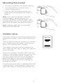
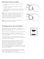
Mounting thermostat
1. Push excess wire back into the wall opening.
2. Close the UWP door. It should remain
closed without bulging.
3. Align the UWP with the thermostat, and
push gently until the thermostat snaps in
place.
Note: If you used the Optional Cover Plate
shown on page 2, remove the gray trim
ring from the thermostat before step 3. Then
align the thermostat with cover plate and push
gently until the thermostat snaps into place.
Note: If needed, gently pull to remove the
thermostat from the UWP
Installer setup
The display will walk you through equipment setup,
connecting to wireless sensors and connecting to
WiFi.
The final step in the setup is a place you can enter
your company name and contact information as
well as your Contractor PRO™ number.
That contact information will be displayed with
alert or reminder messages to keep you connected
to your customer.
Enter your company’s Contractor PRO™ account
number to participate in periodic promotions. Earn
incentives such as bonus points for every T10
Pro Smart thermostat you install during eligible
promotional periods. Your account number is
an 8-digit number that includes a leading zero
(example 01234567).
For questions on this bonus or membership to the
Contractor PRO™ loyalty program, contact us at
18009194835 or contractorpro@resideo.com.
Welcome!

9
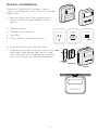
Sensor installation
(Optional C7189R20022 wireless sensor
2-pack sold separate. Up to 20 sensors max per
thermostat)
1. Remove white cover from grey base and
Insert (2) AAA Alkaline batteries in the
sensor.
Devices
& Sensors
Add
2. Open the menu.
3. Tap "Devices & Sensors."
4. Tap "Add."
5. Follow the on-screen instructions.
6. Snap the sensor onto the wall-plate.
7. Adhere the included command strip to the
wall-plate. Then adhere the sensor to the
wall. Level sensor for appearance. (See the
sensor instructions for proper placement.)
WALL
ADHESIVE
STRIP
WALLPLATE
SENSOR

10
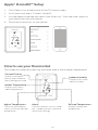
1. Touch Menu icon at the bottom of the T10 home screen.
2. Scroll down and select “Connect HomeKit”.
3. Use the Apple Home App and select “Add Accessory”. Scan the code shown on
your thermostat with your phone.
4. Follow the instructions on your phone.
Apple® HomeKit™ Setup
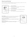
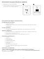
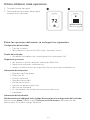
How to use your thermostat
The screen will wake up by pressing the center area of the displayed temperature.
Indoor Temperature
Displays the current
indoor temperature.
Adjust Temperature
Touch the up and down
arrows to set your desired
temperature.
Current Priority
Displays the type of
priority and number of
rooms being prioritized.
Menu
Contains features such as mode,
fan, schedule, priority, and other
thermostat settings.
Indoor Humidity
Displays the current
indoor humidity.
Desired Temperature
Displays the desired
temperature.
74
2
18%
74
2
18%

11
72 72
72 72
72 72
72 72
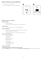
How to use Priority
Priority creates an average temperature in your home based on specific rooms. This
allows you to prioritize comfort where you want it.
Selected Rooms
Rooms you manually select create an average
temperature in your home.
Unselected Room
Will not contribute to the average temperature.
Selected Room
Will contribute to the average temperature.
Active Rooms
Rooms with detected motion are automatically selected
to create an average temperature in your home.
Room without Activity
No motion is detected. Will not contribute to the average
temperature.
Room with Activity
Motion is detected. Will contribute to the average
temperature.

12
How to find more options
Menu options include
Installer Setup
• System type
• IAQ control (hum, dehum, vent) reminders
Installer Test
• Turn on heat, cool, or IAQ equipment
Devices & Sensors
• View, add, or remove RedLINK indoor sensors
• Identity wireless sensors
• Add wireless sensors Device Information
Thermostat Information
• MAC ID number
• IP address
• Date code
• Model number
• Build date
• Stat app
• Firmware version
• Stat app boot #
• Hardware
Dealer Information
Finding date code (pass code) for installer setup.
Open the Menu icon, and choose Thermostat Information. Write down date code.
1 2
Installer Options
1. Touch the menu button.
2. Scroll up and down for more options.

13
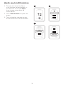
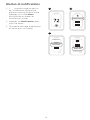
Alerts and notifications
1. The red dot above the Menu
icon indicates an active alert or
notification. Touch the Menu
icon to view active Alerts &
Notifications.
2. Touch Notifications to open this
menu.
3. Touch the alert message to see
more information about the alert.
Notifications
Set the Date
and Time
Notifications
Set the Date
and Time
1 2
3

14
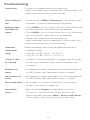
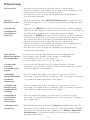
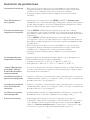
Screen is blank • Check circuit breaker and reset if necessary.
• Make sure power switch at heating and cooling system is on.
• Make sure furnace door is closed securely.
Screen is difficult to
read
• Check setting in MENU/ Preferences / Inactive backlight
brightness or Inactive sleep backlight brightness
Heating or cooling
system does not
respond
• Touch MENU to go to system mode. Set to heat. Make sure
the heat setpoint is above the room temperature.
• Touch MENU to go to system mode. Set to cool. Make sure
the cool setpoint is below the room temperature.
• Check circuit breaker and reset if necessary.
• Make sure power switch at heating & cooling system is on.
• Make sure furnace door is closed securely.
Temperature
settings do not
change
Make sure heating and cooling temperatures are set to
acceptable ranges:
• Heat: 40 °F to 90 °F (4.5 °C to 32.0 °C)
• Cool: 50 °F to 99 °F (10.0 °C to 37.0 °C)
“Cool On” or “Heat
On” is flashing
• Compressor protection feature is engaged. Wait 5 minutes
for the system to restart safely, without damage to the
compressor.
Aux heat runs in
cooling
• For heat pump systems, verify there is not a wire attached to W
on UWP systems. See “Heat pumps systems" on page 7.
Cool runs with a call
for heat
• For heat pump systems, verify there is not a wire attached to W
on UWP systems. See “Heat pumps systems" on page 7.
Heat runs with cooling • Verify there is not a wire attached to W for heat pump
systems. See "Wiring" on pages 67.
Sensor will not
connect
• Press and hold Connect on the wireless sensor for
15 seconds. The LED will turn Amber. Return to the
thermostat menu and press Menu > Devices and Sensors.
Follow the on-screen instructions to add the sensor.
Troubleshooting

15
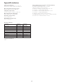
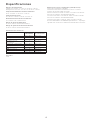
Temperature Ranges
Heat: 40 °F to 90 °F (4.5 °C to 32.0 °C)
Cool: 50 °F to 99 °F (10.0 °C to 37.0 °C)
Operating Ambient Temperature
32 °F to 120 °F (0 °C to 48.9 °C)
Shipping Temperature
20 °F to 120 °F (28.9 °C to 48.9 °C)
Operating Relative Humidity
5% to 90% (non-condensing)
Humidity setting range
10% to 60% RH.
Dehumidity setting range
25% to 80% RH.
Physical Dimensions in inches (mm) (H x W x D)
T10 PRO Smart Thermostat:
4.9" x 3.7" x 0.93" (125.4 x 94.1 x 23.68)
UWP Mounting System (included):
29/32" x 213/64" x 243/64" (58 x 56 x 10)
Cover Plate – (THX321WFS2001W):
511/64" x 51/2" x 11/16" (131 x 140 x 17.5)
Cover Plate – (THX321WF2003W):
67/64" x 67/64" x 9/32" (155 x 155 x 7)
C7189R2002 wireless indoor sensor- ordered separate
2.6” X 2.6” X .77” (66.25 x 66.25 x 19.7)
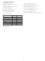
Specifications
Electrical Ratings
Terminal Voltage
(50/60Hz)
Running
Current
W Heating 2030 Vac 0.021.0 A
(Powerpile) 750 mV DC 100 mA DC
W2 (Aux) Heating 2030 Vac 0.021.0 A
E Emergency Heat 2030 Vac 0.020.5 A
Y Compressor Stage 1 2030 Vac 0.021.0 A
Y2 Compressor Stage 2 2030 Vac 0.021.0 A
G Fan 2030 Vac 0.020.5 A
O/B Changeover 2030 Vac 0.020.5 A
L/A Input 2030 Vac 0.020.5 A
U2030 Vac 0.020.5 A
Power Consumption
3 VA

www.resideo.com
© 2020 Resideo Technologies, Inc. All rights reserved.
The Honeywell Home trademark is used under license from Honeywell International, Inc.
This product is manufactured by Resideo Technologies, Inc. and its affiliates.
Tous droits réservés. La marque de commerce Honeywell Home est utilisée avec l’autorisation d’Honeywell
International, Inc. Ce produit est fabriqué par Resideo Technologies, Inc. et ses sociétés affiliées.
Todos los derechos reservados.
La marca comercial Honeywell Home se utiliza bajo licencia de Honeywell International, Inc.
Este producto es fabricado por Resideo Technologies, Inc. y sus afiliados
Resideo Technologies, Inc.
1985 Douglas Drive North, Golden Valley, MN 55422
1-800-633-3991
33-00479EFS—05 M.S. Rev. 11-20 | Printed in United States
CAUTION: MERCURY NOTICE
If this product is replacing a control that contains mercury in a sealed tube, do not place the old control in the trash.
Contact your local waste management authority for instructions regarding recycling and proper disposal.
CAUTION: ELECTRONIC WASTE NOTICE
The product should not be disposed of with other household waste. Check for the nearest authorized collection
centers or authorized recyclers. The correct disposal of end-of-life equipment will help prevent potential negative
consequences for the environment and human health.
CAUTION: EQUIPMENT DAMAGE HAZARD
Compressor protection is bypassed during testing. To prevent equipment damage, avoid cycling the compressor
quickly.
CAUTION: ELECTRICAL HAZARD
Can cause electrical shock or equipment damage. Disconnect power before beginning installation.
5-year limited warranty
Regulatory information
FCC REGULATIONS
§ 15.19 (a)(3)
This device complies with part 15 of the FCC Rules. Operation is subject to the following two conditions:
1 This device may not cause harmful interference, and
2 This device must accept any interference received, including interference that may cause undesired operation.
IC REGULATIONS
RSSGEN
This device complies with Industry Canada’s license-exempt RSSs.
Operation is subject to the following two conditions:
1 This device may not cause interference; and
2 This device must accept any interference, including interference that may cause undesired operation of the device.
FCC Warning (Part 15.21) (USA only)
Changes or modifications not expressly approved by the party responsible for compliance could void the user’s authority to
operate the equipment.
The product should not be disposed of with other household waste. Check for the nearest authorized collection centers or
authorized recyclers. The correct disposal of end-of-life equipment will help prevent potential negative consequences for the
environment and human health.
For Warranty information go to http://honeywellhome.com
Use of the Works with Apple badge means that an accessory has been designed to work specifically with the technology
identified in the badge and has been certified by the developer to meet Apple performance standards. Apple is not responsible
for the operation of this device or its compliance with safety and regulatory standards.
AirPlay, iPad, iPad Air, iPad Pro, iPhone and iPod touch are trademarks of Apple Inc., registered in the U.S. and other countries.
HomePod is a trademark of Apple Inc.

33-00479EFS-05
Modèle TH321WF2003W montré.
Thermostat
intelligent T10 Pro
avec RedLINK™
THX321WFS20 01W
(Détecteur compris)
THX321WF2003W
(Sans détecteur)
Thermostat programmable
Guide d’installation
professionnelle
Lire avant l’installation.
Recherchez des rabais
dans votre région. Les
thermostats Honeywell
Home sont compatibles
avec les programmes des
services publics qui vous
récompensent lorsque vous
économisez de l’énergie.
HoneywellHome.com/Rebates
L’emballage comprend :
• Thermostat intelligent T10 Pro
• Système de montage UWP™
• Adaptateur d’installation standard
(adaptateur pour boîte de jonction)
• Plaque décorative
• Vis et ancrages
• Documentation du thermostat
Compatibilité
• Compatible avec la plupart des systèmes de chauffage et de climatisation et les
thermopompes
• Requis: Alimentation 24 V c.a. (fil C)
• Ne fonctionne pas avec une plinthe électrique (120240 V)
• Ne fonctionne pas avec des systèmes à millivolts
• Téléphone intelligent ou tablette Android ou iOS
Assistance clientèle
WEB honeywellhome.com
TÉLÉPHONE 1 800 6333991

2
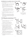
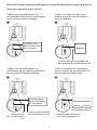
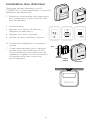
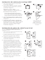
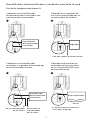
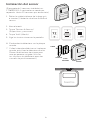
Installation du système de montage UWP
1. Ouvrez l’emballage, puis repérez l’UWP.
Voir la figure 1.
2. Placez l’UWP contre le mur. Placez-le de
niveau, puis marquez l’emplacement des
trous. Voir la figure 2.
Percez les trous aux emplacements
marqués, puis à l’aide d’un marteau,
posez doucement les ancrages de mur
fournis.
‒Si votre boîte contient des goujons
rouges, utilisez un foret de 7/32 po
(5,6 mm). Si votre boîte contient des
goujons jaunes, utilisez un foret de
3/16 po (4,76 mm).
3. Ouvrez la porte, puis insérez les fils dans
les trous de câblage de l’UWP. Voir la
figure 3.
4. Placez l’UWP sur les ancrages. Insérez
et serrez les vis fournies avec l’UWP. Ne
serrez pas excessivement. Serrez jusqu’à
ce que l’UWP soit fixe. Fermez la porte.
Voir la figure 4.
1
2
3
4
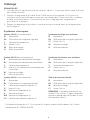
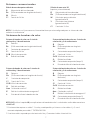
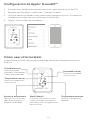
Installation du couvercle en option
Utilisez la plaque du couvercle en option
pour :
• Installez le thermostat sur une boîte
de jonction électrique
• Couvrez les traces de peinture
cachées par l’ancien thermostat.
5. Retirez l’adaptateur de boîte de
jonction du couvercle. Voir la figure 5.
6. Installez l’adaptateur de boîte
de jonction au mur ou sur une
boîte électrique au moyen de
n’importe lesquels des huit trous.
Insérez et serrez les vis fournies
avec le couvercle. Ne serrez pas
excessivement. Assurez-vous que la
plaque adaptatrice est de niveau. Voir
la figure 6.
7. Fixez l’UWP en l’accrochant au crochet
supérieur de l’adaptateur de boîte
de jonction, puis en l’enclenchant en
place par le bas. Voir la figure 7.
8. Enclenchez le couvercle sur
l’adaptateur de boîte de jonction. Voir
la figure 8.
Utiliser les 3 vis fournies
(Nº 8 – 1 ½ po pour les
ancrages rouges; Nº 6
– 1 ½ pour les ancrages
jaunes)
Utilisez les
deux vis
fournies
(nº 6, 5/8 po
[16 mm]).
1/4” to 3/8”
1
2
3 4
1 2
3
4
8
7
6
5
M37809

3
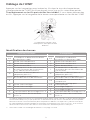
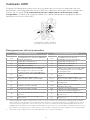
Identification des bornes
Systèmes classiques Thermopompes
Borne Description Borne Description
S/S Entrée pour un détecteur d’intérieur
ou d’extérieur câblé S/S Entrée pour un détecteur
d’intérieur ou d’extérieur câblé
Y Phase 1 du compresseur Y Phase 1 du compresseur
Y2 Phase 2 du compresseur Y2 Phase 2 du compresseur
G Relais de ventilateur G Relais de ventilateur
CFil neutre 24 V c.a. du côté secondaire
du transformateur de climatisation
(s’il y a deux transformateurs) CFil neutre 24 V c.a. du côté
secondaire du transformateur de
climatisation
K* Branchez à la borne K pour un
adaptateur pour fil C K* Branchez à la borne K pour un
adaptateur pour fil C
U/U** Relais de déshumidificateur,
d’humidificateur ou de ventilateur U/U** Relais de déshumidificateur,
d’humidificateur ou de ventilateur
A L/A Raccordement au moniteur du
compresseur
W Phase 1 de chauffage O/B Robinet de jumelage pour
thermopompes
W2 Phase 2 de chauffage Aux Chauffage d’appoint
E Chauffage d’urgence
R Transformateur de chauffage 24 V c.a R Transformateur de chauffage 24 V c.a
Rc Transformateur de climatisation
24 V c.a Rc Transformateur de climatisation
24 V c.a
* Le module Adaptateur pour fil C THP9045A1098 peut être utilisé avec des systèmes de chauffage et
climatisation lorsqu’il n’y a que quatre fils au thermostat et que vous en avez besoin d’un cinquième
comme fil neutre. Utilisez la borne K pour remplacer les bornes Y et G pour les systèmes classiques
ou à thermopompe afin de contrôler le ventilateur et le compresseur avec un seul fil – le fil inutilisé
devient alors le fil neutre. Consultez les instructions du THP9045 pour en savoir plus.
** Consultez la note sur le câblage des bornes U à la page suivante.
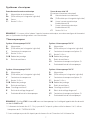
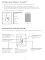
Câblage de l’UWP
Appuyez sur les languettes pour insérer les fils dans le trou de chaque borne
correspondante de l’UWP (un fil par borne) jusqu’à ce qu’ils soient bien entrés.
Tirez légèrement sur les fils pour vérifier leur solidité. Si vous devez débrancher
les fils, appuyez sur la languette de la borne correspondante sur le côté de l’UWP.
Ce câblage est montré à titre
d’exemple. Le vôtre pourrait être
différent.

4
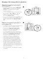
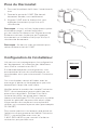
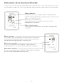
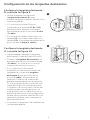
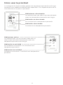
Réglage des languettes à glissière
Réglez la languette à glissière R;
voir la figure 9.
• Utilisez le cavalier intégré (languette
à glissière R) pour faire la différence
entre les systèmes à un ou deux
transformateurs.
• S’il n’y a qu’un fil R et qu’il est raccordé
aux bornes R, Rc ou RH sur l’ancien
thermostat, placez la glissière en
position relevée (1 fil).
• S’il y a un fil raccordé à la borne R et un
autre fil raccordé à la borne Rc, placez
la glissière en position baissée (deux
fils).
Réglez la languette à glissière U;
voir la figure 10.
• Utilisez le cavalier intégré (languette à
glissière U) pour l’appareil de QAI.
• Lorsque la languette à glissière U
est en position abaissée (2 fils), les
contacts U sont de type sec.
• Si votre appareil de QAI est alimenté
par le transformateur de climatisation,
déplacez la languette à glissière U
en position relevée (1 fil). Lorsque
terminé, la borne U inférieure est
raccordée à l’interne à la borne Rc.
Pour cette application, vous devez
raccorder un fil de votre appareil de
QAI à la borne U supérieure et l’autre
au côté neutre du transformateur de
climatisation. Le réglage à un fil est
le plus courant avec l’utilisation d’un
registre d’air frais pour la ventilation ou
d’un ventilateur à basse vitesse pour la
déshumidification.
• Voir les exemples de câblage à la page
suivante.
10
9
La page est en cours de chargement...
La page est en cours de chargement...
La page est en cours de chargement...
La page est en cours de chargement...
La page est en cours de chargement...
La page est en cours de chargement...
La page est en cours de chargement...
La page est en cours de chargement...
La page est en cours de chargement...
La page est en cours de chargement...
La page est en cours de chargement...
La page est en cours de chargement...
La page est en cours de chargement...
La page est en cours de chargement...
La page est en cours de chargement...
La page est en cours de chargement...
La page est en cours de chargement...
La page est en cours de chargement...
La page est en cours de chargement...
La page est en cours de chargement...
La page est en cours de chargement...
La page est en cours de chargement...
La page est en cours de chargement...
La page est en cours de chargement...
La page est en cours de chargement...
La page est en cours de chargement...
La page est en cours de chargement...
La page est en cours de chargement...
-
 1
1
-
 2
2
-
 3
3
-
 4
4
-
 5
5
-
 6
6
-
 7
7
-
 8
8
-
 9
9
-
 10
10
-
 11
11
-
 12
12
-
 13
13
-
 14
14
-
 15
15
-
 16
16
-
 17
17
-
 18
18
-
 19
19
-
 20
20
-
 21
21
-
 22
22
-
 23
23
-
 24
24
-
 25
25
-
 26
26
-
 27
27
-
 28
28
-
 29
29
-
 30
30
-
 31
31
-
 32
32
-
 33
33
-
 34
34
-
 35
35
-
 36
36
-
 37
37
-
 38
38
-
 39
39
-
 40
40
-
 41
41
-
 42
42
-
 43
43
-
 44
44
-
 45
45
-
 46
46
-
 47
47
-
 48
48


Honeywell Home THX321WFS2001W Guide d'installation
- Catégorie
- Thermostats
- Taper
- Guide d'installation