Toro 14in or 16in 60V MAX String Trimmer, Flex-Force Power System 60V MAX Attachment Manuel utilisateur
- Catégorie
- Outils électroportatifs
- Taper
- Manuel utilisateur

Form No. 3460-954 Rev A
Flex-Force Power System™ 14in or 16in 60V MAX String T rimmer
88716
Desbrozadora de hilo 60 V MAX de 36 cm (14") o 41 cm (16") con
Flex-Force Power System™
88716
Débroussailleuse à l Flex-Force Power System™ 60 V MAX de
36 cm (14 po) ou 41 cm (16 po)
88716
www .T oro.com.
*3460-954*


Form No. 3460-951 Rev A
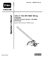
14in or 16in 60V MAX String
T rimmer
Flex-Force Power System
™
60V MAX
Attachment
Model No. 88716 —Serial No. 323000001 and Up
Register at www .T oro.com.
Original Instructions (EN)
*3460-951*

For assistance, please see
www .T oro.com/support
for instructional videos
or contact 1-888-384-9939
before returning this
product.
W ARNING
CALIFORNIA
Proposition 65 W arning
The power cord on this product contains
lead, a chemical known to the State
of California to cause birth defects
or other reproductive harm. W ash
hands after handling.
Use of this product may cause exposure
to chemicals known to the State of
California to cause cancer , birth defects,
or other reproductive harm.
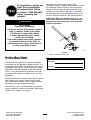
Introduction
This trimmer is intended to be used by residential
homeowners to trim grass as needed outdoors. It is
to be used only by adults. It is designed to be used in
combination with the T oro Flex-Force Power System
60V MAX Attachment-Capable Power Head Model
51810T . Using this product for purposes other than
its intended use could prove dangerous to you and
bystanders.
Read this information carefully to learn how to operate
and maintain your product properly and to avoid
injury and product damage. Y ou are responsible for
operating the product properly and safely .
V isit www .T oro.com for product safety and operation
training materials, accessory information, help nding
a dealer , or to register your product.
Whenever you need service, genuine the
manufacturer parts, or additional information, contact
an Authorized Service Dealer or the manufacturer
Customer Service and have the model and serial
numbers of your product ready . Figure 1 identies
the location of the model and serial numbers on the
product. W rite the numbers in the space provided.
Important: W ith your mobile device, you can
scan the QR code on the serial number decal (if
equipped) to access warranty , parts, and other
product information.
g426370
Figure 1
1. Model and serial number location
Model No.
Serial No.
© 2023—The T oro® Company
81 1 1 L yndale A venue South
Bloomington, MN 55420
2
Contact us at www .T oro.com.
Printed in China
All Rights Reserved

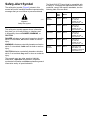
Safety-Alert Symbol
The safety-alert symbol ( Figure 2 ) shown in this
manual and on the machine identies important safety
messages that you must follow to prevent accidents.
g000502
Figure 2
Safety-alert symbol
The safety-alert symbol appears above information
that alerts you to unsafe actions or situations and
is followed by the word DANGER ,W ARNING , or
CAUTION .
DANGER indicates an imminently hazardous situation
which, if not avoided, will result in death or serious
injury .
W ARNING indicates a potentially hazardous situation
which, if not avoided, could result in death or serious
injury .
CAUTION indicates a potentially hazardous situation
which, if not avoided, may result in minor or moderate
injury .
This manual uses two other words to highlight
information. Important calls attention to special
mechanical information and Note emphasizes general
information worthy of special attention.
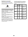
The Model 51810T Power Head is compatible with
a variety of T oro-approved attachments that, when
combined, comply with specic standards; see the
following table for more detail.
Combination
Power
Head
Model
Attachment
Model
Standard
String
T rimmer
51810T 88716
Conforms to
UL STD 82
Certied to CSA
STD C22.2 No. 147
Edger 51810T 88710
Conforms to
UL STD 82
Certied to CSA
STD C22.2 No. 147
Pole Saw
51810T 88714
Conforms to
UL STD 82
Certied to CSA
STD C22.2 No. 147
Cultivator
51810T 88715
Conforms to
UL STD 82
Certied to CSA
STD C22.2 No. 147
Hedge
T rimmer
51810T 88713
Conforms to UL
STD 62841-4-2
Certied to CSA STD
C22.2 62841-4-2
3

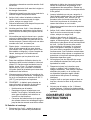
Safety
IMPORT ANT SAFETY
INSTRUCTIONS
W ARNING
When using electric gardening tools, always
read and follow basic safety warnings and
instructions to reduce the risk of re, electric
shock, and personal injury , including the
following:
Read All Instructions
I. T raining
1. The operator of the tool is responsible for any
accidents or hazards occurring to others or their
property .
2. Do not allow children to use or play with the
tool, battery pack, or the battery charger; local
regulations may restrict the age of the operator .
3. Do not allow children or untrained people to
operate or service this device. Allow only people
who are responsible, trained, familiar with the
instructions, and physically capable to operate
or service the device.
4. Before using the tool, battery pack, and battery
charger , read all the instructions and cautionary
markings on these products.
5. Become familiar with the controls and proper use
of the tool, battery pack, and battery charger .
II. Preparation
1. Keep bystanders and children away from the
operating area.
2. Use only the battery pack specied by T oro.
Using other accessories and attachments may
increase the risk of injury and re.
3. Plugging the battery charger into an outlet that is
not 120 V can cause a re or electric shock. Do
not plug the battery charger into an outlet other
than 120 V . For a dif ferent style of connection,
use an attachment plug adapter of the proper
conguration for the power outlet if needed.
4. Do not use a damaged or modied battery
pack or battery charger , which may exhibit
unpredictable behavior that results in re,
explosion, or risk of injury .
5. If the supply cord to the battery charger is
damaged, contact an Authorized Service Dealer
to replace it.
6. Charge the battery pack with only the battery
charger specied by T oro. A charger suitable for
1 type of battery pack may create a risk of re
when used with another battery pack.
7. Charge the battery pack in a well-ventilated area
only .
8. Follow all charging instructions and do
not charge the battery pack outside of the
temperature range specied in the instructions.
Otherwise, you may damage the battery pack
and increase the risk of re.
9. Do not operate the tool without all guards and
other safety protective devices in place and
functioning properly on the tool.
10. Dress properly—W ear appropriate clothing,
including eye protection; long pants; substantial,
slip-resistant footwear; rubber gloves; and
hearing protection. T ie back long hair and do
not wear loose clothing or loose jewelry that can
get caught in moving parts. W ear a dust mask in
dusty operating conditions.
III. Operation
1. A void dangerous environments—Do not use the
tool in rain or in damp or wet locations.
2. Use the proper tool for your application—Using
the tool for purposes other an its intended use
could prove dangerous to you and bystanders.
3. Prevent unintentional starting—Ensure that the
switch is in the O FF position before connecting
to the battery pack and handling the tool. Do
not carry the tool with your nger on the switch
or energize the tool with the switch in the O N
position.
4. Operate the tool only in daylight or good articial
light.
5. If the tool strikes an object or starts to vibrate,
immediately shut of f the tool, wait for all moving
parts to stop, and disconnect the battery before
examining the tool for damage. Make all
necessary repairs before resuming operation
6. Remove the battery pack from the tool before
adjusting it or changing accessories.
7. Keep your hands and feet away from the cutting
area and all moving parts.
8. Shut of f the tool, remove the battery pack from
the tool, and wait for all movement to stop before
adjusting, servicing, cleaning, or storing the tool.
9. Remove the battery pack from the tool whenever
you leave it unattended.
10. Do not force the tool—Allow the tool to do the
job better and safer at the rate for which it was
designed.
1 1. Do not overreach—Keep proper footing and
balance at all times, especially on slopes. W alk,
never run with the tool.
4

12. Stay alert—W atch what you are doing and use
common sense when operating the tool. Do not
use the tool while ill, tired, or under the inuence
of alcohol or drugs.
13. Ensure that the ventilation openings are kept
clear of debris.
14. Under abusive conditions, the battery pack may
eject liquid; avoid contact. If you accidently
come into contact with the liquid, ush with
water . If the liquid contacts your eyes, seek
medical help. Liquid ejected from the battery
pack may cause irritation or burns.
15. Do not expose a battery pack or tool to re or
excessive temperature. Exposure to re or
temperature above 130°C (265°F) may cause
explosion.
16. CAUTION—A mistreated battery pack may
present a risk of re, explosion, or chemical
burn.
•Do not disassemble the battery pack.
•Replace the battery pack with a genuine
T oro battery pack only; using another type of
battery pack may cause a re or risk of injury .
•Keep battery packs out of the reach of
children and in the original packaging until
you are ready to use them.
IV . Maintenance and Storage
1. Maintain the tool with care—Keep it clean and
in good repair for best performance and to
reduce the risk of injury . Follow the instructions
for lubricating and changing accessories. Keep
handles dry , clean, and free from oil and grease.
2. When the battery pack is not in use, keep it
away from metal objects such as paper clips,
coins, keys, nails, and screws that can make a
connection from 1 terminal to another . Shorting
the battery terminals may cause burns or a re.
3. Keep your hands and feet away from moving
parts.
4. Shut of f the tool, remove the battery pack from
the tool, and wait for all movement to stop before
adjusting, servicing, cleaning, or storing the tool.
5. Check the tool for damaged parts—If there
are damaged guards or other parts, determine
whether it will operate properly . Check for
misaligned and binding moving parts, broken
parts, mounting, and any other condition that
may af fect its operation. Unless indicated in the
instructions, have an Authorized Service Dealer
repair or replace a damaged guard or part.
6. Do not replace the existing non-metallic cutting
means on the tool with a metallic cutting means.
7. Do not attempt to service or repair the tool,
battery pack, or battery charger except as
indicated in the instructions. Have an Authorized
Service Dealer perform service using identical
replacement parts to ensure that the product is
safely maintained.
8. Store an idle tool indoors in a place that is dry ,
secure, and out of the reach of children.
9. Do not dispose of the battery in a re. The
cell may explode. Check with local codes for
possible special disposal instructions.
SA VE THESE
INSTRUCTIONS
5

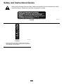
Safety and Instructional Decals
Safety decals and instructions are easily visible to the operator and are located near any area
of potential danger . Replace any decal that is damaged or missing.
decal139-5346
139-5346
decal139-5210
139-5210
1. W arning—read the Operator ’ s Manual ; stay away from
moving parts; keep all guards in place; wear eye protection;
do not operate in wet conditions.
6

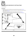
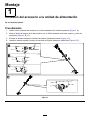
Setup
1
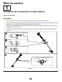
Connecting the Attachment to the Power Head
No Parts Required
Procedure
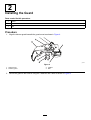
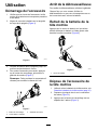
1. Install the square shaft of the attachment into the square shaft of the power head (A of Figure 3 ).
2. Align the locking button on the lower shaft with the slotted hole on the upper shaft and slide the 2 shafts
together (B and C of Figure 3 ).
3. The locking button clicks into the slotted hole when the shafts are secured (C of Figure 3 ).
4. Using the screw-handle, tighten the screw on the shaft connector until it is secure (D of Figure 3 ).
g372305
Figure 3
7

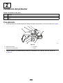
2
Installing the Guard
Parts needed for this procedure:
1
Guard
4 W asher
4 Bolt
Procedure
1. Align the trimmer guard beneath the guard mount as shown in Figure 4 .
g333216
Figure 4
1. Guard mount
3. W asher
2. T rimmer guard 4. Bolt
2. Secure the guard to the trimmer using the 4 washers and 4 bolts as shown in Figure 4 .
8

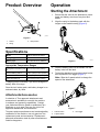
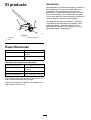
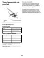
Product Overview
g372306
Figure 5
1. Guard
3. Bump button
2. String
Specications
Model 88716, attaches to 51810T
Charger T ype
T oro 60V lithium-ion chargers
Battery T ype T oro 60V lithum-ion batteries
Appropriate T emperature Ranges
Charge/store the battery pack
at
5°C (41°F) to 40°C (104°F)*
Use the battery pack at
-30°C (-22°F) to 49°C (120°F)
Use the trimmer at
0°C (32°F) to 49°C (120°F)
Store the trimmer at 0°C (32°F) to 49°C (120°F)*
*Charging time will increase if you do not charge the
battery within this range.
Store the tool, battery pack, and battery charger in an
enclosed clean, dry area.
Attachments/Accessories
A selection of T oro approved attachments and
accessories is available for use with the machine
to enhance and expand its capabilities. Contact
your Authorized Service Dealer or authorized T oro
distributor or go to www .T oro.com for a list of all
approved attachments and accessories.
T o ensure optimum performance and continued safety
certication of the machine, use only genuine T oro
replacement parts and accessories. Replacement
parts and accessories made by other manufacturers
could be dangerous.
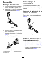
Operation
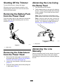
Starting the Attachment
1. Ensure that the vents on the attachment, power
head, and battery are clear of any dust and
debris.
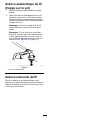
2. Align the cavity in the battery pack with the
tongue on the handle housing ( Figure 6 ).
g357444
Figure 6
3. Push the battery pack into the handle until the
battery locks into the latch.
4. T o start the attachment, press the lockout button,
then squeeze the run trigger ( Figure 7 ).
Note: Slide the 2-speed switch to change the
speed of the attachment.
g357456
Figure 7
1. Lockout button 3. Run trigger
2. 2-speed switch
9

Shutting Off the T rimmer
T o shut of f the trimmer , release the trigger .
Whenever you are not using the trimmer or are
transporting the trimmer to or from the work area,
remove the battery pack.
Removing the Battery Pack
from the Power Head
Press the battery latch on the machine to release the
battery pack and slide the battery pack out of the
machine ( Figure 8 ).
g357457
Figure 8
1. Battery latch
Removing the Attachment
from the Power Head
1. Ensure that the battery pack is removed from
the power head; refer to Removing the Battery
Pack from the Power Head ( page 10 ) .
2. Loosen the screw-handle on the shaft connector
(Figure 3 ).
3. Press the locking button down while pulling the
2 shafts apart ( Figure 3 ).
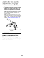
Advancing the Line Using
the Bump Feed
1. Run the trimmer at full throttle.
2. T ap the bump button on the ground to advance
the line. The line advances each time the bump
button is tapped. Do not hold the bump button
on the ground.
Note: The line trimming cut-of f blade on the
grass deector cuts the line to the correct length.
Note: If the line is worn too short, you may not
be able to advance the line by tapping it on the
ground. If so, release the trigger and refer to
Advancing the Line Manually ( page 10 ) .
g331007
Figure 9
1. Bump button
Advancing the Line
Manually
Remove the battery pack from the trimmer , then push
the bump button at the base of the spool retainer
while pulling on the trimmer line to manually advance
the line.
10

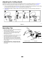
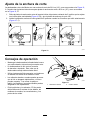
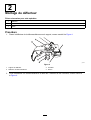
Adjusting the Cutting Swath
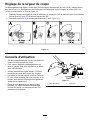
The trimmer comes from the factory with a cutting swath of 36.6 cm (14 inches) as shown in A of Figure 10 .
Refer to the following instructions to adjust the swath to 40.6 cm (16 inches) as shown in D of Figure 10 .
1. Remove the swath blade from the bottom of the guard by removing the 2 screws holding it in place using
the provided Allen wrench (B of Figure 10 ) and rotate the swath blade 180°.
2. Once the swath blade is rotated, install it onto the guard using the 2 screws previously removed (C of
Figure 10 ).
g427004
Figure 10
Operating T ips
•Keep the trimmer tilted toward the area being cut;
this is the best cutting area.
•The string trimmer cuts when you move it from
right to left. This prevents the trimmer from
throwing debris at you.
•Use the tip of the string to do the cutting; do not
force the string head into uncut grass.
•Wire and picket fences can cause the string to
wear rapidly and even break. Stone and brick
walls, curbs, and wood can also cause the string
to wear rapidly .
•A void trees and shrubs. The string can easily
damage tree bark, wood moldings, siding, and
fence posts.
g330996
Figure 1 1
1. Direction of rotation 2. String path
1 1

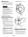
Maintenance
After each use of the trimmer , complete the following:
1. Remove the battery from the power head.
2. Wipe the trimmer clean with a damp cloth. Do
not hose the trimmer down or submerge it in
water .
CAUTION
The line cutoff blade on the deector is
sharp and can cut you.
Do not use your hands to clean the
deector shield and blade.
3. Wipe or scrape clean the cutting head area any
time there is an accumulation of debris.
4. Check and tighten all fasteners. If any part is
damaged or lost, repair or replace it.
5. Brush debris away from air intake vents and
exhaust on motor housing to prevent the motor
from overheating.
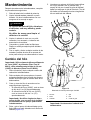
Replacing the String
Important: Use only 2 mm (0.080 inch) diameter
monolament string (T oro Part No. 8861 1) or 2.4
mm (0.095 inch) diameter twisted monolament
string (T oro Part No. 88202).
1. Remove the battery pack and clean any debris
from the trimmer head.
2. Remove any old string on the spool by
repetitively pressing the bump button while
pulling the line out equally from both sides of the
trimmer .
3. Cut a piece of string according to the following
specications.
•If you are using 2 mm (0.080 inch) string, cut
one piece of line approximately 4.9 m (16 ft).
•If you are using 2.4 mm (0.095 inch) twisted
string, cut one piece of line approximately 3
m (10 ft).
Important: Do not use any other gauge
or type of string, and do not exceed the
recommended length as this could damage
the trimmer .
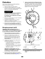
4. Press and turn the knob on the string head until
arrow on the knob aligns with arrow on the string
head ( Figure 12 ).
5. Insert 1 end of the line at an angle into the LINE
IN eyelet and push the line through the string
head track until it comes out through the eyelet
on the other side. Pull the line though the string
head until the line outside the string is evenly
divided on each side.
g330983
g330985
Figure 12
Disassembled view shown for clarity
1. Arrows 4. Eyelet
2. Knob
5. String
3. String head
6. T rack
Important: Do not disassemble the trimmer
head.
6. Hold the string head in place with one hand.
With your other hand, rotate the knob in the
direction shown by the arrows (clockwise).
7. Wind the line, leaving about 102 mm (4 inches)
extending beyond the eyelet on each side.
12

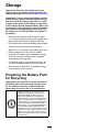
Storage
Important: Store the tool, battery pack, and
charger only in temperatures that are within the
appropriate range; refer to Specications ( page 9 ) .
Important: If you are storing the battery pack for
the off-season, remove the battery pack from the
tool and charge the battery pack until 2 or 3 LED
indicators turn green on the battery . Do not store
a fully charged or fully depleted battery . When you
are ready to use the tool again, charge the battery
pack until the left indicator light turns green on
the charger or all 4 LED indicators turn green on
the battery .
•Disconnect the product from the power supply
(i.e., remove the plug from the power supply or the
battery pack) and check for damage after use.
•Do not store the tool with the battery pack installed.
•Clean all foreign material from the product.
•When not in use, store the tool, battery pack, and
battery charger out of the reach of children.
•Keep the tool, battery pack, and battery charger
away from corrosive agents, such as garden
chemicals and de-icing salts.
•T o reduce the risk of serious personal injury , do
not store the battery pack outside or in vehicles.
•Store the tool, battery pack, and battery charger
in an enclosed clean, dry area.
Preparing the Battery Pack
for Recycling
Important: Upon removal, cover the terminals of
the battery pack with heavy-duty adhesive tape.
Do not attempt to destroy or disassemble the
battery pack or remove any of its components.
Lithium-ion battery packs labeled with the
Call2Recycle seal can be recycled at any
participating retailer or battery recycling
facility in the Call2Recycle program (US
and Canada only). T o locate a participating
retailer or facility closest to you, please call
1-800-822-8837 or visit www .call2recycle.org.
If you cannot locate a participating retailer or
facility nearby , or if your rechargeable battery
is not labeled with the Call2Recycle seal,
please contact your local municipality for more
information on how to responsibly recycle the
battery . If you are located outside of the US
and Canada, please contact your authorized
T oro distributor .
13

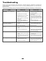
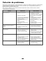
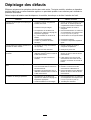
T roubleshooting
Perform only the steps described in these instructions. All further inspection, maintenance, and repair work
must be performed by an authorized service center or a similarly qualied specialist if you cannot solve the
problem yourself.
Always remove the battery from the tool when troubleshooting, inspecting, maintaining, or cleaning the tool.
Problem
Possible Cause Corrective Action
1. The battery is not fully installed in the
tool.
1. Remove and then replace the battery
into the tool, making sure that it is fully
installed and latched.
2. The battery pack is not charged.
2. Remove the battery pack from the tool
and charge it.
3. The battery pack is over or under the
appropriate temperature range.
3. Move the battery pack to a place
where it is dry and the temperature is
between 5°C (41°F) and 40°C (104°F).
4. There is moisture on the leads of the
battery pack.
4. Allow the battery pack to dry or wipe it
dry .
5. The battery pack is damaged. 5. Replace the battery pack.
The tool does not run or does not run
continuously .
6. There is another electrical problem
with the tool.
6. Contact an Authorized Service Dealer .
1. The battery pack charge capacity is
too low .
1. Remove the battery pack from the tool
and fully charge the battery pack.
The tool does not reach full power or the
motor housing is getting hot.
2. The air vents are blocked.
2. Clean the air vents.
1. There is debris under the grass shield
or in the bump head housing on the
trimmer .
1. Clean any debris from under the grass
shield or in the bump head housing.
The tool is producing excessive vibration
or noise.
2. The spool is not properly wound. 2. Advance the line using the bump head
and/or remove the line on the spool
and wind the spool again.
1. The trimmer is out of line.
1. Add more line to the bump head.
2. The line is tangled in the bump head
housing.
2. Remove the bump head cover and
untangle the line.
The bump head does not advance the line.
3. There is debris under the grass shield
or in the bump head housing on the
trimmer .
3. Clean any debris from under the grass
shield or in the bump head housing.
1. The battery pack is over or under the
appropriate temperature range.
1. Move the battery pack to a place
where it is dry and the temperature is
between 5°C (41°F) and 40°C (104°F).
The battery pack loses charge quickly .
2. The trimmer is overloaded. 2. T rim at a slower pace.
14

Notes:

California Proposition 65 W arning Information
What is this warning?
Y ou may see a product for sale that has a warning label like the following:
W ARNING: Cancer and Reproductive Harm—www .p65W arnings.ca.gov .
What is Prop 65?
Prop 65 applies to any company operating in California, selling products in California, or manufacturing products that may be sold in or brought into
California. It mandates that the Governor of California maintain and publish a list of chemicals known to cause cancer , birth defects, and/or other
reproductive harm. The list, which is updated annually , includes hundreds of chemicals found in many everyday items. The purpose of Prop 65 is to
inform the public about exposure to these chemicals.
Prop 65 does not ban the sale of products containing these chemicals but instead requires warnings on any product, product packaging, or literature with
the product. Moreover , a Prop 65 warning does not mean that a product is in violation of any product safety standards or requirements. In fact, the
California government has claried that a Prop 65 warning “is not the same as a regulatory decision that a product is ‘safe’ or ‘unsafe.’” Many of these
chemicals have been used in everyday products for years without documented harm. For more information, go to https://oag.ca.gov/prop65/faqs-view-all .
A Prop 65 warning means that a company has either (1) evaluated the exposure and has concluded that it exceeds the “no signicant risk level”; or (2)
has chosen to provide a warning based on its understanding about the presence of a listed chemical without attempting to evaluate the exposure.
Does this law apply everywhere?
Prop 65 warnings are required under California law only . These warnings are seen throughout California in a wide range of settings, including but not
limited to restaurants, grocery stores, hotels, schools, and hospitals, and on a wide variety of products. Additionally , some online and mail order
retailers provide Prop 65 warnings on their websites or in catalogs.
How do the California warnings compare to federal limits?
Prop 65 standards are often more stringent than federal and international standards. There are various substances that require a Prop 65 warning
at levels that are far lower than federal action limits. For example, the Prop 65 standard for warnings for lead is 0.5 μg/day , which is well below
the federal and international standards.
Why don’t all similar products carry the warning?
•Products sold in California require Prop 65 labelling while similar products sold elsewhere do not.
•A company involved in a Prop 65 lawsuit reaching a settlement may be required to use Prop 65 warnings for its products, but other companies
making similar products may have no such requirement.
•The enforcement of Prop 65 is inconsistent.
•Companies may elect not to provide warnings because they conclude that they are not required to do so under Prop 65; a lack of warnings for a
product does not mean that the product is free of listed chemicals at similar levels.
Why does T oro include this warning?
T oro has chosen to provide consumers with as much information as possible so that they can make informed decisions about the products they buy and
use. T oro provides warnings in certain cases based on its knowledge of the presence of one or more listed chemicals without evaluating the level of
exposure, as not all the listed chemicals provide exposure limit requirements. While the exposure from T oro products may be negligible or well within the
“no signicant risk” range, out of an abundance of caution, T oro has elected to provide the Prop 65 warnings. Moreover , if T oro does not provide these
warnings, it could be sued by the State of California or by private parties seeking to enforce Prop 65 and subject to substantial penalties.
Rev A

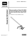
Form No. 3460 - 952 Rev A
Desbrozadora de hilo 60 V MAX
de 36 cm (14") o 41 cm (16")
Accesorio Flex - Force Power System
™
60 V
MAX
Nº de modelo 88716 —Nº de serie 323000001 y superiores
Registre su producto en www .T oro.com.
T raducción del original (ES)
*3460 - 952*

Si necesita ayuda, consulte
los vídeos instruccionales
en www .T oro.com/support
o llame al 1 - 888 - 384 - 9939
antes de devolver este
producto.
ADVERTENCIA
CALIFORNIA
Advertencia de la Propuesta 65
El cable eléctrico de este producto
contiene plomo, que el Estado de
California sabe que causa defectos
congénitos u otros peligros para la
reproducción. Lávese las manos después
de manejar el material.
El uso de este producto puede provocar la
exposición a sustancias químicas que el
Estado de California considera causantes
de cáncer , defectos congénitos u otros
trastornos del sistema reproductor .
Introducción
Esta desbrozadora está diseñada para ser usada por
usuarios domésticos para cortar la hierba en espacios
exteriores. Debe ser utilizada únicamente por adultos.
Está diseñada para ser usada en combinación con
la unidad de potencia de cabezal intercambiable
Flex - Force Power System 60 V MAX de T oro, Modelo
51810T . El uso de este producto para otros propósitos
que los previstos podría ser peligroso para usted y
para otras personas.
Lea este manual detenidamente para aprender a
utilizar y mantener correctamente su producto, y
para evitar lesiones y daños al producto. Usted es
responsable de utilizar el producto de forma correcta
y segura.
V isite www .T oro.com para buscar materiales
de formación y seguridad o información sobre
accesorios, para localizar un distribuidor o para
registrar su producto.
Si necesita asistencia técnica, piezas genuinas
del fabricante o información adicional, póngase en
contacto con un Servicio Técnico Autorizado o con
el Servicio de atención al cliente del fabricante, y
tenga a mano los números de serie y de modelo
del producto. Figura 1 identica la ubicación de los
números de modelo y serie en el producto. Escriba
los números en el espacio provisto.
Importante: Con su dispositivo móvil, puede
escanear el código QR de la pegatina del número
de serie (en su caso) para acceder a información
sobre la garantía, las piezas, y otra información
sobre el producto.
g426370
Figura 1
1. Ubicación de los números de modelo y de serie
Nº de modelo
Nº de serie
© 2023—The T oro® Company
81 1 1 L yndale A venue South
Bloomington, MN 55420
2
Póngase en contacto con nosotros en www .T oro.com.
Impreso en China
Reservados todos los derechos
La page est en cours de chargement...
La page est en cours de chargement...
La page est en cours de chargement...
La page est en cours de chargement...
La page est en cours de chargement...
La page est en cours de chargement...
La page est en cours de chargement...
La page est en cours de chargement...
La page est en cours de chargement...
La page est en cours de chargement...
La page est en cours de chargement...
La page est en cours de chargement...
La page est en cours de chargement...
La page est en cours de chargement...
La page est en cours de chargement...
La page est en cours de chargement...
La page est en cours de chargement...
La page est en cours de chargement...
La page est en cours de chargement...
La page est en cours de chargement...
La page est en cours de chargement...
La page est en cours de chargement...
La page est en cours de chargement...
La page est en cours de chargement...
La page est en cours de chargement...
La page est en cours de chargement...
La page est en cours de chargement...
La page est en cours de chargement...
La page est en cours de chargement...
La page est en cours de chargement...
La page est en cours de chargement...
La page est en cours de chargement...
-
 1
1
-
 2
2
-
 3
3
-
 4
4
-
 5
5
-
 6
6
-
 7
7
-
 8
8
-
 9
9
-
 10
10
-
 11
11
-
 12
12
-
 13
13
-
 14
14
-
 15
15
-
 16
16
-
 17
17
-
 18
18
-
 19
19
-
 20
20
-
 21
21
-
 22
22
-
 23
23
-
 24
24
-
 25
25
-
 26
26
-
 27
27
-
 28
28
-
 29
29
-
 30
30
-
 31
31
-
 32
32
-
 33
33
-
 34
34
-
 35
35
-
 36
36
-
 37
37
-
 38
38
-
 39
39
-
 40
40
-
 41
41
-
 42
42
-
 43
43
-
 44
44
-
 45
45
-
 46
46
-
 47
47
-
 48
48
-
 49
49
-
 50
50
-
 51
51
-
 52
52


Toro 14in or 16in 60V MAX String Trimmer, Flex-Force Power System 60V MAX Attachment Manuel utilisateur
- Catégorie
- Outils électroportatifs
- Taper
- Manuel utilisateur