Maytag MDE22PD Installation Instructions Manual
- Catégorie
- Sèche-linge électriques
- Taper
- Installation Instructions Manual
Ce manuel convient également à

COMMERCIAL HE DRYER iNSTALLATiON iNSTRUCTiONS
Electric
iNSTRUCTiONSD'INSTALLATIOND'UN SECHE-LINGEHECOMMERCIAL
Eiectrique
INSTRUCCIONES DE INSTALACION- SECADORA HE COMERCIAL
El_ctrica
ISTRUZION!D'INSTALLAZIONE- ASCIUGATRICEHE COMMERCIALE
Elettrica
MDE22PD
W10239206A
www.maytagcommerciaNaundry.com

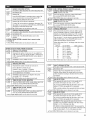
TABLEOF CONTENTS
DRYER SAFETY ............................................................................ 3
DRYER DISPOSAL ...................................................................... 3
INSTALLATION REQUIREMENTS .............................................. 4
Tools and Parts .......................................................................... 4
Location Requirements .............................................................. 4
E{ectrical Requirements ............................................................ 5
Venting Requirements .............................................................. 6
INSTALLATION INSTRUCTIONS - ELECTRIC DRYER .......... 7
install Leveling Legs.................................................................... 7
Electrical Connection .................................................................. 8
Connect Vent .............................................................................. 8
Complete installation ................................................................ 8
MAINTENANCE INSTRUCTIONS ............................................. 8
REVERSING THE DOOR SWING ............................................. 9
ELECTRONIC CONTROL SETUP .......................................... 11
WAR RAN TY .............................................................................. 15
TABLEDESMATIERES
SECURITE DU SECHE-LINGE ................................................ 16
ELIMINAT}ON DU SECHE-L{NGE .......................................... 16
EXIGENCES D'INSTALLATION ................................................ 17
Outillage et pi_ces .................................................................... 17
Exigences d'emp}acement ...................................................... 17
Speciftcat{ons electriques ....................................................... 18
Exigences concemant revacuat}on .......................................... 19
INSTRUCTIONS D'INSTALLAT{ON - SECHE-LINGE
ELECTRIQUE ............................................................................ 21
installation des pieds de nivetlement ........................................ 21
Raccordement electrique ........................................................ 21
Raccordement du conduit d'evacuation ................................ 21
Achever I'instatlation ................................................................ 22
INSTRUCTIONS D'ENTRETIEN ............................................... 22
INVERS{ON DU SENS D'OUVERTURE DE LA PORTE ......... 23
REGLAGE DE LA CARTE
DE CIRCUITS ELECTRONIQUES .......................................... 25
GARANTIE ................................................................................ 29
P
INDICE
SEGURIDAD DE LA SECADORA ............................................ 30
ELIMINACI6N DE LA SECADORA .......................................... 30
REQUISITOS DE INSTALACION ............................................ 31
Piezas y herramientas .......................................................... 31
Requisitos de ubicaci6n ........................................................ 31
Requisitos electricos ............................................................ 32
Requisitos de ventilaci6n .................................................... 33
INSTRUCCIONES DE INSTALACION -
SECADORA ELECTRICA ........................................................ 34
Instalaci6n de las paras nivetadoras .................................... 34
Cone×i6n electrica ................................................................ 35
Cone×i6n del conducto de escape ...................................... 35
Complete la instataci6n ........................................................ 35
INSTRUCCIONES DE MANTENIMIENTO ............................. 35
COMO INVERT{R EL SENTIDO DE APERTURA
DE LA PUERTA ....................................................................... 36
PROGRAMACION DEL CONTROL ELECTRONICO ............ 38
GARANTIA ................................................................................ 42
INDICE
SICUREZZA DELL'ASCIUGATRICE ........................................ 43
L'ELIMINAZIONE DELL'ASCIUGATRICE .................................. 43
REQUIS{TI D'INSTALLAZIONE ................................................ 44
Attrezzi e componenti .............................................................. 44
Requisiti di ubicazione ............................................................ 44
Requisiti elettrici ...................................................................... 45
Requisiti di scarico .................................................................. 46
ISTRUZIONI D'INSTALLAZIONE - ASCIUGATRICE
ELETTRICA ............................................................................ 47
Instatlazione dei piedini di regolazione .................................... 47
Connessione etettrica .............................................................. 48
Connessione dello scarico ...................................................... 48
Comptetamento dell'instatlazione ............................................ 48
ISTRUZIONI DI MANUTENZIONE ......................................... 48
INVERSIONE DELLA ROTAZIONE D{ APERTURA ............... 49
CONFIGURAZIONE DEI CONTROLLI ELETTRONICl .......... 51
GARANZIA .................................................................................. 55

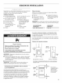
DRYERSAFETY
Your safety and the safety of others are very important.
We have provided many important safety messages in this manua{ and on your appliance. Always read and obey a{{ safety
messages.
This is the safety a{ert symbol.
This symbol alerts you to potential hazards that can kill or hurt you and others.
AI{ safety messages wi{{ fo{{ow the safety a{ert symbo{ and either the word "DANGER" or "WARN{NG."
These words mean:
You can be killed or seriously injured if you don't immediately
follow instructions.
You can be killed or seriously injured if you don't follow
instructions.
AHsafety messages will tell you what the potential hazard is, te{I you how to reduce the chance of injury, and tell you what can
happen if the instructions are not followed.
FOR YOUR SAFETY
1. Do not use or store petrol or other flammable materials in this appliance or near this appliance.
2. Do not spray aerosols in the vicinity of this appliance while it is in operation.
3. Do not modify this appliance.
DRYERDISPOSAL
This appliance is marked according to the European directive 2002/96/EC on Waste Electrical and Electronic Equipment
(WEEE).
By ensuring this product is disposed of correctly, you will help avoid potential negative consequences for the environment and
human health, which could otherwise be caused by inappropriate waste handling of this product.
The symbol on the product, or on the documents accompanying the product, indicates that this appliance may not be treated
as household waste. Instead it shall be handed over to the applicable collection point for the recycling of electrical and
electronic equipment.
Disposal must be carried out in accordance with local environmental regulations for waste disposal.
For more detailed information about treatment, recovery and recycling of this product, please contact your local city office, your
household waste disposal service or the shop where you purchased the product.
3

INSTALLATIONREQUIREMENTS
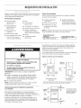
Gather the required tools and parts before starting installation.
Read and follow the instructions provided with any tools
listed here.
Tools needed:
[] 200 mm (8") or 250 mm [] 8 mm (-%o")socket wrench
(10") Pipe wrench [] Utility knife
[] 200 mm (8") or 250 mm [] Vent clamps
(10") Adjustable wrench
[] Sealing compound gun
[] Flat-blade screwdriver and sealing compound (for
[] Phillips screwdriver installing new exhaust vent)
[] Adjustable wrench that [] Pliers
opens to 25 mm (1") or [] Stiff-bladed putty knife
hex-head socket wrench
[] Level
Parts supplied:
Remove parts bag from dryer drum. Check that all parts were
included.
[] Foot boot (4) [] PN models: Card reader
[] Dryer foot (4) bezel, card reader wire
harness, hardware
[] PD models: Cam for
service door lock
NOTE: The circuit diagram for this dryer is located inside the
lower front panel, within the Tech Sheets.
Technical
Specifications:
220 - 240 v, 50 Hz. AC
Clothes Capacity:
9 Kg Max.
Explosion Hazard
Keep flammable materials and vapors, such as petrol,
away from dryer.
Do not install in a garage.
Failure to do so can result in death, e×plosion, or fire.
IMPORTANT: Observe all governing codes and ordinances.
[] Check code requirements: Some codes limit or do not permit
installation of clothes dryers in garages, closets, or sleeping
quarters. Contact your local building inspector.
[] Do not install on carpet.
NOTE: The dryer must not be installed in an area where it will be
exposed to water and/or weather.
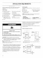
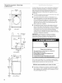
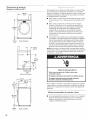
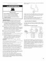
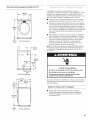
Recessed Area and Closet Installation instructions
This dryer may be installed in a recessed area or closet. This
dryer must not be installed behind a lockable door, a sliding door,
or a door with a hinge on the opposite side to that of the dryer.
The installation spacing is in millimeters and is the minimum
allowable. Additional spacing should be considered for ease
of installation, servicing, and compliance with local codes
and ordinances.
If installed in a closet with a door, the minimum unobstructed air
opening in the top and bottom is required. Louvered doors
with equivalent air openings are acceptable.
The dryer must be exhausted outdoors.
No other fuel-burning appliance may be installed in the same
closet as the dryer.
Minimum Installation Clearances
381 mm
Os")
o o
EZ3_-.-
Ornrn _ Ornm
(o") "--_ (o")
Recessed front view
356 rnm
(14") max
Closet
door
J
cl
/ .... I
....... 0ram
(0")
_1 ]_2s mm11")
Closet side view
Additional clearances for wall, door, and floor moldings may be required or if
external exhaust elbow is used.
(48 in._)
Front
view
(24in._)
0
L
76 mm (3")
--F
closet
door
76 mm (3")
*Opening is the minimum
for a closet door. Louvered
doors with equivalent air
openings are acceptable.

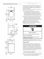
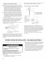
Product Dimensions 686 mm (27") dryer
686 mm
(27")
m===t
25 mm
(1")
FRONT VIEW
ELECTRIC
102mm(4")
dia.
-,_358 mm_.._
(14")
BACK VIEW
t
715 mm
- ,
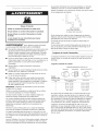
This dryer is supplied without an electric cord and plug. It must
be connected by a competent electrician to a single-phase
electricity supply at the voltage shown on the dataplate, using a
suitable fixed wiring installation in accordance with local and
national wiring regulations.
[] A 3-wire circular cord of minimum conconductor size 2.5 mm2
cross-section area should be used.
[] A 30A supply fuse should be used, and a switch having
a contact separation in both poles that provides full
disconnection under over-voltage category Ill conditions
must be incorporated into the fixed wiring inaccordance with
local wiring regulations. The dryer should be positioned so
that the disconnection switch is easily accessible to the user.
[] A cord clamp bush is provided on the dryer, and should be
tightened on completion of wiring. The electrical mains
terminals are located behind the small rear access panel
(terminal block cover), and connections should be made in
accordance with the terminal markings. Remember to replace
the terminal access panel (terminal block cover).
NOTE: In accordance with the European EMC Directive
(2004/108/EC), the maximum electricity supply system
impedance to which the electric dryer should be connected
is declared to be 0.29 Ohm + j0.18 Ohm.
Electric Shock Hazard
This is a 3=wire appliance which must be earthed.
Do not earth to a gas pipe.
Failure to follow these instructions could result in
death, fire, or serious injury.
203 mm
(8")
921 mm
(36i/4")
25 mm
(1")
736 mm
, (29) 695 mm
_ i (27114,,)
/ 1
SIDE VlEW
If codes permit and an additional earth bond wire is used, it is
recommended that a qualified electrician determine that the earth
bond path is adequate.
AUSTRALIA ONLY
For Australia, each single electric dryer is fitted with a cord
and plug, with conductors of 2.5 mm2cross sectional area,
and should be plugged into a suitable electrical socket at the
voltage shown on the dataptate. Do not use extension lead
assemblies on commercial installations. If the supply cord is
damaged, it must be replaced with a specially terminated cord
by an authorized service agent or a similarly qualified person in
order to avoid a hazard. Each electric dryer for other countries
is supplied without an electric cord and plug.
Recommended Earthing Method
[] It is your responsibility to contact a qualified electrical installer
to ensure that the electrical installation is adequate and in
conformance with all local codes and ordinances.
5

Fire Hazard
Use a heavy metal vent.
Do not use a plastic vent.
Do not use a metal foil vent.
Failure to follow these instructions can result in death
or fire.
WARNING: To reduce the risk of fire, this dryer MUST BE
EXHAUSTED OUTDOORS.
[] Adequate ventilation has to be provided to avoid the backflow
of gases into the room from appliances burning other fuels,
including open fires (i.e. available airflow into the room should
match airflow out from the room).
[] The dryer vent must not be discharged into a flue which is
used for exhausting fumes from appliances burning gas or
other fuels, chimney, wall, ceiling, or a concealed space of
a building, or any other vent used for venting.
[] Do not use an exhaust hood with a magnetic latch.
[] Do not install flexible metal vent in enclosed walls, ceilings,
or floors.
[] 102 mm (4") heavy metal vent and clamps must be used.
[] Use clamps to seat all joints. Vent must not be connected
or secured with screws or other fastening devices which
extend into the interior of the vent and catch lint. Do not use
duct tape.
iMPORTANT: Observe all governing codes and ordinances.
Use a heavy metal vent. Do not use plastic or metal foil vent.
Rigid metal vent is recommended to avoid crushing
and kinking.
Flexible metal vent must be fully extended and supported when
the dryer is in its final position. Remove excess flexible metal
vent to avoid sagging and kinking that will result in reduced
airflow and poor performance.
An exhaust hood should cap the vent to keep rodents and
insects from entering the building.
Exhaust hood must be at least 305 mm (12") from the ground
or any object that may be in the path of the exhaust (such as
flowers, rocks, or bushes).
If using an existing vent system, clean lint from the entire length
of the system and make sure exhaust hood is not plugged with
lint. Replace any plastic or metal foil vent with rigid metal or
flexible metal vent.
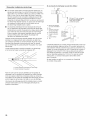
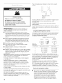
Plan installation to use the fewest number of elbows and turns.
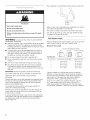
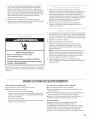
ExhaustAir Flow
A.Good
B.Better
Allow as much room as possible when using elbows or making
turns. Bend vent gradually to avoid kinking.
Vent outlet is located at the center of the bottom dryer back.
The vent can be routed up, down, left, right, behind the dryer,
or straight out the back of the dryer.
Vent System Length
Maximum length of vent system depends upon the type of vent
used, number of elbows, and type of exhaust hood.
Maximum Vent Length
102 mm (4") Exhaust Hoods
Box Louvered 64 mm (2V/') Angled
Rigid MetalVent _ (_
No. of 900 turns Box Hood and Louvered Style Angled Hood Style
0 39.6 m (130 ft.) 39.3 m (129 ft.)
1 38.1 m (125 ft.) 36.3 m (119 ft,)
2 35.1 m (115 ft.) 33.2 m (109 ft,)
3 32.3 m (106 ft.) 30.5 m (100 ft.)
4 98 m (98 ft.) 28 m (92 ft.)
If dryer is installed in a confined area, such as a bedroom,
bathroom, or closet, provision must be made for enough air
for combustion and ventilation. (Check governing codes and
ordinances.) See "Recessed Area and Closet Installation
Instructions" in the "Location requirements" section.
A 102 mm (4") outlet hood is preferred. However, a 64 mm
(2_/2") outlet exhaust hood may be used. A 64 mm (2W')
outlet creates greater back pressure than other hood types.
For permanent installation, a stationary vent system is required.

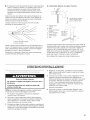
Multiple Dryer Venting
[] A main vent can be used for venting a group of dryers. Main
vent should be sized to remove 5663 I/min (200 CFM) of air
per dryer. Large-capacity lint screens of proper design may be
used in the main vent if checked and cleaned frequently. The
room where the dryers are located should have make-up air
equal to or greater than the airflow of all the dryers in the
room.
[] A back-draft damper kit is needed and is available from a
commercial laundry distributor; it should be installed in the
vent of each dryer to keep exhausted air from returning
into the dryers and to keep the exhaust in balance within
the main vent. Unobstructed return air openings are required.
Each vent should enter the main vent at an angle pointing in the
direction of the airflow. Vents entering from the opposite side
should be staggered to reduce the exhausted air from interfering
with the other vents.
The maximum angle of each vent entering the main vent should
be no more than 30°.
A. Individual dryer vent
B. Main vent
Keep air openings free of dry cleaning fluid fumes. Fumes create
acids which, when drawn through the dryer heating units, can
damage dryers and items being dried.
A clean-out cover should be located on the main vent for periodic
cleaning of the vent system.
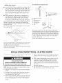
If an exhaust hood cannot be used:
Min. 300 mm (12") clearance
above any accumulation
of snow, ice, or debris such
as leaves.
A. Exhaust hood or elbow
B. Wall
C. Main collector vent
D. Horizontal vent
E. 180° sweep elbow
E Vertical vent
G. Roof
610 mm(24")
min. above
highestpoint
of building
G
C
The outside end of the main vent should have a sweep elbow
directed downward. If the main vent travels vertically through the
roof, rather than through the wall, install a 180 ° sweep elbow on
the end of the vent at least 610 mm (2 ft.) above the highest part
of the building. The opening in wall or roof shall have a diameter
13 mm (1_,)larger than the vent diameter. The vent should be
centered in the opening.
Do not install screening or cap over the end of the vent.
INSTALLATIONINSTRUCTIONS-ELECTRICDRYER
Excessive Weight Hazard
Use two or more people to move and install dryer.
Failure to do so can result in back or other injury.
NOTE: Slide dryer onto cardboard or hardboard before moving
to avoid damaging floor covering.
1. Using two or more people, move dryer to desired installation
location.
2. Take tape off front corners of dryer. Open dryer and remove
the literature and parts packages. Wipe the interior of the
drum thoroughly with a damp cloth.
3. Take two of the cardboard corners from the carton and place
them on the floor in back of the dryer. Firmly grasp the body
of the dryer and gently lay it on its back on the cardboard
corners.
4. With one of the legs in hand, check the ridges for a diamond
marking. That's how far the leg is supposed to go into the
hole.
5. Start to screw the leveling legs into the holes by hand. (Use
a small amount of liquid detergent to lubricate the screw
threads so it is easier to turn the legs.) Use a 1" (25 mm)
wrench or socket wrench to finish turning the legs until you
reach the diamond mark. Then fit a protective foot boot over
each foot.
Now stand the dryer up.
6. Remove cardboard or hardboard from under dryer. Adjust the
legs of the dryer up or down until the dryer is level.
7

Electric Shock Hazard
This is a 3-wire dryer which must be earthed.
Securely tighten all electrical connections.
Failure to do so can result in death, fire, or
electric shock.
This dryer is supplied without an electric cord and plug;
it must be connected by a competent electrician.
In Australia, each single electric dryer is fitted with a cord
and plug. See "Electrical Requirements."
1. Using a 102 mm (4") clamp, connect vent to exhaust outlet
in dryer. If connecting to existing vent, make sure the vent is
clean. The dryer vent must fit over the dryer exhaust outlet
and inside the exhaust hood. Make sure the vent is secured
to exhaust hood with a 102 mm (4") clamp.
2. Move dryer into final position. Do not crush or kink vent.
Make sure dryer is level.
1. With dryer in final position, place level on top of the dryer,
first side to side; then front to back. If the dryer is not level,
adjust the legs of the dryer up or down until the dryer is level.
2. Switch on power supply.
3. Check dryer operation:
Press the selection button for a full cycle and let the dryer run
for at least five minutes. Dryer will stop when time is used up.
NOTE: Dryer door must be closed for dryer to operate.
When door is open, dryer stops, but timer continues to run.
To restart dryer, close door and press a cycle button.
4. Start the dryer and allow it to complete a full cycle to make
sure it is working properly.
MAINTENANCEINSTRUCTIONS
Maintenance instructions:
mClean lint screen after each cycle.
mRemoving accumulated lint:
• From inside the dryer cabinet:
Lint should be removed every 2 years or more often,
depending on dryer usage. Cleaning should be clone
by a qualified person.
• From the exhaust vent:
Lint should be removed every 2 years, or more often,
depending on dryer usage.
If dryer does not operate, check the following:
[] Electric supply is connected.
[] Circuit breaker is not tripped or fuse is not blown.
[] Door is closed. Listen closely to hear door switch(es) activate.
[] Selected cycle button has been pressed firmly and display
shows cycle time.
If you need assistance:
Contact your authorized Maytag Commercial Laundry distributor
or visit: www.MaytagCommerciatLaundry.com. When you call,
you will need the dryer model number and serial number.
Both numbers can be found on the serial-rating plate located
on your appliance.

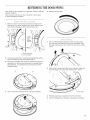
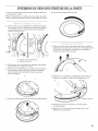
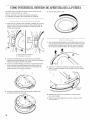
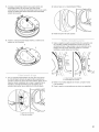
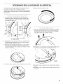
REVERSINGTHEDOORSWING
Door swing can be changed from a right-side opening to left-side
opening, if desired.
Place a towel or soft cloth on top of the dryer or work space
to avoid damaging the surface.
5. Rotate outer door 180°.
1.
2.
3.
Remove 3 of the 4 screws that hold the door hinge on the
front panel of the dryer. Partially loosen the remaining screw
with keyhole opening and lift the door off the screw.
\
Loosen
screw
with
keyhole
opening
A. Dryer front panel
B. Door assembly
Lay the door assembly on a previously prepared flat surface
with the inside (inner door assembly) facing up.
Remove the 6 Phillips head screws to release the outer door
assembly from the inner door assembly, as indicated below.
See illustration. It is important that you remove only the 6
indicated screws.
4. Lift the inner door assembly off the outer door assembly.
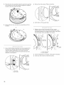
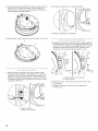
(J
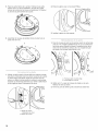
1.
Use a small flat-blade screwdriver to remove 2 plug strips
from the inner door. Slide the head of the screwdriver under
the plugs, being certain not to scratch the inner door surface.
Lift up.
2.
Remove the 4 screws that attach to the inner door hinge and
move the hinge to the other side. Reinstall the 4 screws.
, \
Door hinge
3. Reinstall plug strips on opposite side of the inner door.
4. Check for fingerprints on the glass. Clean glass if necessary.
9

5. Place the inner door assembly inside the outer door assembly.
To fit correctly, the inner door assembly edge fits completely
inside the outer door assembly edge.
2. Remove the strike using a Phillips screwdriver.
6.
1.
Reassemble the inner and outer door assemblies with the
6 screws.
Use a small flat-blade screwdriver to remove ptug strip from
the dryer door opening. Slide the head of the screwdriver
under the plugs, being certain not to scratch the dryer
surface. Lift the plastic strip from the dryer slowly to avoid
distortion of the ptug strip.
3. Insert strike on the opposite side.
1.
2.
3.
Reattach door to dryer front panel with the 4 screws.
Partially install the screw with keyhole opening first, and fit
the keyhole opening in the hinge over the screw. Then install
the remaining 3 screws and tighten alt 4 screws.
Instafl this
screw first
A. Dryerfront panel
B. Door assembly
Check for fingerprints on the glass. Clean glass if necessary.
Close door and check that it latches securely.
A. Plug strip
B. Door strike
10

ELECTRONICCONTROL SETUP
Electric Shock Hazard
Disconnect power before servicing.
Replace all parts and panels before operating.
Failure to do so can result in death or
electrical shock.
iMPORTANT
Electrostatic Discharge (ESD)
Sensitive Electronics
ESD is present everywhere. ESD may damage or weaken the
electronic control assembly. The new control assembly may
appear to work well after repair is finished, but failure may
occur at a later date due to ESD stress.
[] Use an anti-static wrist strap. Connect wrist strap to green
earth connection point or unpainted metal in the appliance.
-OR-
Touch your finger repeatedly to a green earth connection point
or unpainted metal in the appliance.
[] Before removing the part from its package, touch the
anti-static bag to a green earth connection point or
unpainted metal in the appliance.
[] Avoid touching electronic parts or terminal contacts; handle
electronic control assembly by edges only.
[] When repackaging failed electronic control assembly in
anti-static bag, observe above instructions.
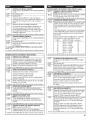
GENERAL USER INFORMATION
"out of order" showing in display
This condition indicates the dryer is inoperative. Diagnostic or failure
code will follow the scrolling message.
'0 Minutes' showing in display
This condition indicates the dryer cannot be operated. Coins
dropped or debit inputs during this condition will be stored in escrow
but cannot be used until normal operation is restored by opening
and closing the door. If a door switch fails, it must be replaced
before normal operation can be restored.
Cold Start (initial first use)
Dryer is programmed at the factory as follows:
[] 45 minutes dry time for PN models; 5 minutes per coin
for PD models.
[] 1.50 dry price (fixed cycle with top off - PD Models).
[] 0.00 dry price (fixed cycle - PN Models).
Warm Start (after power failure)
A few seconds after power is restored, if a cycle was inprogress
at the time of the power failure, 'RESELECT CYCLE' will flash
in the display. This isto indicate the need for a fabric setting
button to be pressed to restart dryer.
Pricing
After the door is opened and closed following the completion of
a cycle, the display indicates the cycle price (unless set for free
operation). As coins or debit inputs arrive, the display will change
to lead the user through the initiation of a cycle.
There are four (4)types of pricing:
Fixed 'Vend' Pricing
A dryer set up for 'Fixed Cycle' operation can only accept additional
time accumulated by increments equal to the length of a complete
dry cycle. A maximum of 99 minutes may be purchased; no
additional credit is given when 99 minutes is in the display.
Accumulator Pricing
If the price is set to one coin 1,then accumulator mode is in effect.
Cycle time can be purchased one coin at atime (PD models) up to
the maximum time of 99 minutes.
Fixed Cycle With Top Off Pricing
A dryer set to offer 'Top Off' capability will allow time to be added to
an existing dry cycle in increments equal to the number of minutes
of dry time per coin (coin 1),up to 99 minutes, regardless of the cost
required to start the dryer. No credit is given for coins or debit inputs
entered when the control is displaying 99 minutes.
PN Models Set Up As PR: In Enhanced Debit Mode, the top off
price can be set independently (seeVALUE OF COIN 2), and the top
off time is calculated according to the following equation:
top off price = top off time
full cycle price full cycle length
Hundredth increment offset is not applied to top off purchases.
PN Models
The factory has preset the cycle price to zero. When this happens,
'SELECT CYCLE' will appear rather than a cycle price. Any cycle
started as a free cycle will automatically terminate when the door
is opened.
Debit Card Ready
This dryer has a control that is debit card ready, but the dryer is not.
11

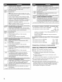
CONTROLS_UPPROCEDURES
IMPORTANT: Read all instructions before operating.
The fabric setting buttons along with the digital display are used
to set-up the dryer controls.
The display can contain 4 numbers and/or letters and a decimal
point. These are used to indicate the set-up codes and related code
values available for use in programming the dryer.
Now to use the buttons to program the controls
1. The WHITES AND COLORS button is used to adjust the
values associated with set-up codes. Pressing the button will
increment the value by one (1). Rapid adjustment is possible
by holding the button down.
2. The PERM. PRESS button advances the display through the set-
up codes. Pressing the button will advance the display to the next
available set-up code. Holding the button down will automatically
advance through the set-up codes at a rate of one (1)per second.
3. The DELICATES button is used to select or deselect options.
Start Operating Set-Up
mPD Models: Insert service door key,turn, and lift to remove
access door.
mPN Models: Remove the AA1 jumper from the control board, see
procedure below, or use the Service Access Code below. Once the
debit card reader is installed (according to the reader manufacturer's
instructions), the set-up mode can be entered by inserting a manual
set-up card (supplied by the reader manufacturer) into the card slot.
Ifmanual set-up card is not available, manual set-up mode cannot
be entered. However, diagnostic mode can be entered by removing
connector AA1 on the circuit board.
IMPORTANT: The console must not be opened unless power is
first removed from the dryer. Toaccess connector AA1 :
-> Unplug dryer or disconnect power.
-> Open console, disconnect plug on AA1, close console.
-> Plug in dryer or reconnect power.
mPN Models Equipped with Programming Switch: Insert access
panel key and turn counter-clockwise.
mPN Models with Gen. 2 Debit Card Reader: Once a Gen. 2 debit
card reader is installed (according to the reader manufacturer's
instructions), the set-up mode can only be entered by inserting
a manual set-up card (supplied by the reader manufacturer)
into the card slot.
If manual set-up card is not available, only diagnostic mode
can be entered.
mAlternate method of entering Set-up Mode by entering Service
Access Code: This code can be entered to access set-up mode
without removing the console on dryers just removed from the
carton, or not yet programmed. The Service Access Code only
functions on dryers set up for 0 vend price without any Special
Pricing set-up, and the Coin/Debit Option must be set to "J._d".
Ifthe dryer is not in failure mode, the door must be opened to
proceed. Using only the three bottom buttons (numbered 1,2,
and 3 from left to right):
1. Press 2 for longer than 2 seconds but less than 10 seconds.
2. Press 1 & 3 simultaneously for 2 seconds. Display shows S 3.
3. Press 1 & 2 simultaneously. Display shows S 4.
4. Press 2 & 3 simultaneously. Display shows S 5.
5. Press 2.
6. Wait at least 2 seconds, but not more than 15 seconds,
then press in succession: 3, 2, 1,3.
The dryer is now in the set-up mode.
Before proceeding, it is worth noting that, despite attthe options
available, an owner can simply choose to uncrate a new commercial
dryer, hook it up, plug it in, and have a dryer that operates. NOTE:
PD models require a payment system or OPL kit to be installed prior
to operation.
mPD dryers are pre-set at the factory for fixed cycle price with top off.
mPN dryers are pre-set for fixed cycle operation, and they can be
run without payment.
12
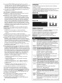
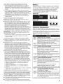
DISPLAY
After the dryer has been installed and plugged in,the display will
show '0 minutes.'
Once the dryer has been plugged in and the dryer door opened
and closed, the display wilt show the vend price. PN models are
factory preset for free cycles; the display will flash 'SELECT CYCLE'.
PD Models
WHITES PERM.
AND COLORS PRESS DELICATES
PN Mode(s
WHITES PERM.
AND COLORS PRESS DELICATE8
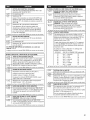
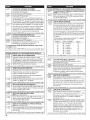
SST-UP CODSS
FOR PN MODELS: The set-up codes are the same as for the PD
models except where noted.
Theset-up code is indicated bythe one or two left hand characters.The
set-up code value is indicated by the two or three right hand characters.
NOTE: The first line of each code indicates the factory default.
REGULAR CYCLE PRICE
¢.Tn ¢.T
c1_ Representsthe numberofcoins(coin1);mayadjustfrom 0-39
(Seeb.xxset-upfor VALUEOFC01N1).Advancefrom 0-39by
pressingWHITESANDCOLORS.Factorydefaultof 6 x coin1.
c_J__ PNMODELS:Factorydefaultof 600, or0 coins.
-> PressPERM.PRESSbuttononceto advanceto nextcode.
L_u S REGULAR DRY TIME
/ _ Representsthe numberofminutespercoin(coin1).
Factorydefaultd 5 minutespercoin.
Example:6 coinsx 5 minutes=30 minutes.
BypressingtheWHITESANDCOLORSbutton,valueadjusts
from 1-99minutes.
_ PNMODELS:Representsthe cyclelengthfor freecycles.
Asexample:'745' =45 minutes.
-> PressPERM.PRESSbuttononceto advanceto nextcode.
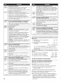
L_U u TYPE OF DRYER PRICING
oc_ FixedCyclewith TopOff.Fordetaileddescription,seeGeneral
UserInformation.
J-_c _- FixedCycle.Fordetaileddescription,seeGeneralUser
Information.
UseDELICATESbuttonto makethisselection.
PNMODELS:FactorydefaultofFC.
-> PressPERM.PRESSbuttononceto advanceto nextcode.
_u u CYCLE COUNTER OPTION
This optioniseitherSELECTED'ON'or NOTSELECTED'OFF'.
-_J-_L"""""_NotSelected'OFF'.
_-7_ Selected'ON'and not ableto bedeselected.PressDELICATES
button3 consecutivetimes to select'ON'.Onceselected'ON'
it cannotbedeselected.
-> PressPERM.PRESSbuttononceto advanceto nextcode.

MONEYCOUNTEROPTION
ThisoptioniseitherSELECTED'ON'or NOTSELECTED'OFF'.
i._ NotSelected'OFF'.
i._ Selected'ON'.
PressDELICATESbutton3 consecutivetimes to select'ON'
and3 consecutivetimes to remove(NotSelected'OFF'.)
Counterresetsbygoingfrom 'OFF'to 'ON'.
i._ Selected'ON'and not ableto bedeselected.
Toselect'ON'andnot ableto bedeselected,first select'ON',
thenwithintwo secondspressDELICATEStwice, WHITESAND
COLORSonce,andexittheset-upmode.
-e PressPERM.PRESSbutton onceto advanceto nextcode.
J__.uu SPECIAL PRICING OPTION
This option iseitherSELECTED'ON'or NOTSELECTED'OFF'.
c._ NotSelected'OFF'.
"_co
_--.-_L_ Selected'ON'.PressDELICATESbuttononcefor this
selection.
ifSPECIALPRICINGOPTIONis selected, there is accessto codes
'3.' through 'g.'
-> PressPERM.PRESSbuttononceto advanceto nextcode.
OPTIONSTO USEIF SPECIALPRICINGISSELECTED:
=_.L.__ SPECIAL CYCLE PRICE
-7._ Representsthe numberof coins(coin 1); mayadjustfrom
0-39. (Seeb.xxset-upforVALUEOFCOIN1).Advancefrom
0-39 by pressingWHITESANDCOLORS.Factorydefaultof
6x coin1.
PNMODELS:Factorydefaultof 0 coins.
-_ PressPERM.PRESSbuttononceto advanceto nextcode.
LJ /_
_.u S SPECIAL DRY TIME
%_._ Representsthe numberof minutespercoin(coin1).
Factorydefaultof 5minutespercoin.
Example:6 coinsx 5 minutes=30 minutes.
BypressingtheWHITESANDCOLORSbutton,thevalue
canbeadjustedfrom 1-99minutes.
%_._ PNMODELS:Representsthecyclelengthfor freecycles.
Asexample:'4 45' =45 minutes.
-e PressPERM.PRESSbuttononceto advanceto nextcode.
cr_r_
u u TIME-OF-DAY CLOCK, MINUTES
C I-I I-I
__._ This isthe TIME-OF-DAYCLOCK,minutesetting;select0-59
minutesbypressingWHITESANDCOLORSbutton.
-> PressPERM.PRESSbuttononceto advanceto nextcode.
LT I-I I-I
_j_j TIME-OF=DAY CLOCK, HOURS
NOTE:Usesthe 24 hr.clock.
¢.Tm r_ 1
c,.J-e_3 This isthe TIME-OF-DAYCLOCK,hour setting;select0-23
hoursby pressingWHITESANDCOLORSbutton.
-e PressPERM.PRESSbuttononceto advanceto nextcode.
OPTIONSTOUSEIFSPECIALPRICINGIS SELECTED(continued):
d!_LJLJ SPECIAL PRICE START HOUR
NOTE:Usesthe 24 hr.clock.
-I1-11-1
/._ This isthe starthour,0-23 hours. SelectSTARTHOUR
by pressingWHITESANDCOLORSbutton.
•e PressPERM.PRESSbuttononceto advanceto nextcode.
f'l nn
CLO_.LJLJ SPECIAL PRICE STOP HOUR
NOTE:Usesthe 24 hr.clock.
f'l nn
o. J__,,,,,,,,,,,,_This isthe stop hour; 0-23 hours.SelectSTOPHOUR
by pressingWHITESANDCOLORSbutton.
•e PressPERM.PRESSbuttononceto advanceto nextcode.
_,'__,'_
I u SPECIAL PRICE DAY
,'_ _r_ This representsthe dayof the weekandwhether special
pricing isselectedfor that day.A numberfollowedby '0'
indicatesno selectionthat particularday (9.10).A number
followedbyan'S' indicatesselectedfor that day (9.1S).
Daysofweek(1-7) canbe chosenby pressingtheWHITES
ANDCOLORSbutton.Press DELICATESbutton onceto
selectspecialpricingfor eachdaychosen.
Whenexitingsetupcode'9.',the displaymustshowcurrent
dayofweek:
DISPLAY DAYOFWEEK CODE(selected)
10 Day1 =Sunday 1S
20 Day2 =Monday 2S
30 Day3 =Tuesday 3S
40 Day4 =Wednesday 4S
50 Day5 =Thursday 5S
60 Day6 =Friday 6S
70 Day7 =Saturday 7S
-e PressPERM.PRESSbutton onceto advanceto nextcode.
_CF
VAULT VIEWING OPTION
This optionis eitherSELECTED'ON'or NOTSELECTED'OFF'.
NotSelected'OFF'.
Selected'ON'.PressDELICATESbutton oncefor this
selection.Whenselected,the moneyand/orcyclecounts
will beviewable(if counting isselected)whenthe coinbox
is removed.
-e PressPERM.PRESSbutton onceto advanceto nextcode.
_u-_ VALUE OF COIN 1
_._ This representsthe valueofcoin 1 in the quantityof 5%
incrementsofthe largercoinvalue.5x 5% =25%.
Bypressingthe WHITESANDCOLORSbutton,thereis the
optionof 1-199for the quantityof 5%increments.
With coin slideactivation,this representsthetotal vendprice.
-e PressPERM.PRESSbutton onceto advanceto nextcode.
F _f_
,_.._cu VALUE OF COIN 2
This representsthe valueofcoin 2 in the quantityof 5%
incrementsofthe largercoinvalue.20x 5%= 100%.
Bypressingthe WHITESANDCOLORSbutton,thereis the
optionof 1-199for the quantityof 5%increments.
rm.'_
_._ PNMODELS:This representsthe valueofcoin 2in the
quantityof 5% incrementsofthe largercoinvalue.Factory
default= 5x 5% ofthe largercoinvalue.
PNMODELSUSINGENHANCEDDEBIT:This representsthe
valueoftop off in quantityof 5% incrementsof the largercoin
value.Factorydefault=5x 5%of the largercoinvalue.
-> PressPERM.PRESSbuttononceto advanceto nextcode.
13

¢L_.UU COIN SLIDE OPTION
This option iseitherSELECTED'ON'or NOTSELECTED'OFF'.
Replacementof metercasewill beneededforcoinslidemounting.
inn
o.u&_ NotSelected'OFF'.
o_ Selected'ON'.
NOTE:This option needsto besetto '00' unlessthe
metercasehasbeenchangedto accepta coinshe device.
PressDELiCATESbutton3 consecutivetimes for this
selection.Whencoinslidemode isselected,set'b.' equalto
vane of slide in coins.Set'6 xx' (REGULARCYCLEPRICE)
and'3.xx' (SPECIALCYCLEPRICE)to numberof slide
operations.6 01 &3.01 =1 slidepush.
NOTE:ifthe installersetsup 'CS'ona coindrop model,
itwill not registercoins.
--->PressPERM.PRESSbutton onceto advanceto nextcode.
J_.uu ADD COINS OPTION
This option iseitherSELECTED'ON'or NOTSELECTED'OFF'.
This optioncausesthe customerdisplayto showthe number
of coins (coin 1)to enter,ratherthanthe amount.
cnn
_.._ NotSelected'OFF'.
c._ Selected'ON'.
PressDELiCATESbutton3consecutivetimesfor thisselection.
PNMODELS:This optionis not selectable.
--->PressPERM.PRESSbutton onceto advanceto nextcode.
fF_ i
,-_d._co COIN/DEBIT OPTION
II- I
,_,._ Bothcoin & debitselected.(NOTAVAILABLE)
fF
u._ Coinsselected,debit disabled.
PressDELICATESbutton3consecutivetimesfor thisselection.
f I
,.J.-L_o DebitCardselected,coin disabled.Defaultfor PN models,
andfor PNoperation,mustbesetasJ._d.
PressDELICATESbutton3consecutivetimesfor thisselection.
,.._._ EnhancedDebitis self-selectedwhen a Generation2 card
readeris installedinthe dryer.The'Ed'option cannotbe
manuallyselectedor deselected.(NOTAVAEABLE)
-e PressPERM.PRESSbutton onceto advanceto nextcode.
c_,juu PRICE SUPPRESSION OPTION
This option iseitherSELECTED'ON'ORNOTSELECTED'OFF'.
This optioncausesthe customerdisplayto show'AVAILABLE'
or 'ADD'ratherthanthe amountof moneyto add.(Used
mainlyin debitinstallations.)
I al"_
__._ NotSelected'OFF'.
e c Selected'ON'.PressDELICATESbuttononceforthis selection.
c._
--->PressPERM.PRESSbutton onceto advanceto nextcode.
_.c c CLEAR ESCROW OPTION
This option iseitherSELECTED'ON'ORNOTSELECTED'OFF'.
Whenselected,moneyheldin escrowfor30 minuteswithout
furtherescrowor cycleactivitywill becleared.
n._ Selected'ON'.
aa
n.&_ NotSelected'OFF'.PressDELICATESbuttononcetodeselect
thisoption.
-->PressPERM.PRESSbuttononceto advanceto nextcode.
, _n n HUNDREDTH INCREMENT OFFSET
IUdU U
II I-I1-1
u._ Thisrepresentsthe hundredthincrementpriceoffsetused
in Generation2 (EnhancedDebit)PNmodelssetupwith card
reader.Choosefrom0-4hundredthsbypressingtheWHITES
ANDCOLORSbutton.(NOTAVAILABLE)
--_PressPERM.PRESSbuttononceto advanceto nextcode.
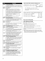
If cycle counter (90C) is selected, the following is true:
1 O0 Represents the number of cycles in HUNDREDS. 102 = 200
2 O0 Represents the number of cycles in ONES. 2 2.5= 25
TOTAL CYCLES = 225
This is 'VIEW ONLY' and cannot be cleared.
Press the PERM. PRESS button once to advance
to next code.
If money counter (1.0C or 1.00) isselected, the following is true:
3 O0 Currency amount in HUNDREDS. 3 01 = 100.00
4 O0 Currency amount in ONES. 4 68 = 68.00
5 O0 Currency amount in HUNDREDTHS. 5 7.5= 00.75
TOTAL = 168.75
END OF SET-UP PROCEDURES
EXIT FROM SET-UP MODE
[] PD MODELS: Reinstall access door.
[]
[]
PN MODELS where AA1 plug was removed:
1. Unplug dryer or disconnect power.
2. Open console, reinsert jumper into AA1, close console.
3. Plug in dryer or reconnect power.
PN WITH PROGRAMMING SWITCH: Turn key clockwise and
remove.
If Service Access Code was used to enter set-up mode: From
Set-up Code 8, press button #1 for 4 seconds, wait 2 minutes
without touching any buttons (without diagnostic modes running),
or power down the dryer, then reapply power.
14

MAYTAG COMMERCIAL WASHEK DRYEK STACKED DRYE
DRYER, COMMERCIAL STACK LAUNDRY, AND MULTI-LOAD
COIN OPERATED COMMERCIAL WASHERS AND DRYERS
WAR NTY
LiMiTED WARRANTY ON PARTS
For the first five years from the date of purchase, when this commercial appliance is installed, maintained and operated according to the
instructions attached to or furnished with the product, Maytag brand of Whirlpool Corporation (thereafter "Maytag") will pay for factory
specified parts or original equipment manufacturer parts to correct defects in materials or workmanship. Proof of original purchase date
is required to obtain service under this warranty.
ITEMS MAYTAG WILL NOT PAY FOR
1. All other costs including labor, transportation, or custom duties.
2. Service calls to correct the installation of your commercial appliance, to instruct you how to use your commercial appliance, to
replace or repair fuses, or to correct external wiring or plumbing.
3. Repairs when your commercial appliance is used for other than normal, commercial use.
4. Damage resulting from improper handling of product during delivery, theft, accident, alteration, misuse, abuse, fire, flood, acts of
God, improper installation, installation not in accordance with local electrical or plumbing codes, or use of products not approved
by Maytag.
5. Pickup and Delivery. This commercial appliance is designed to be repaired on location.
6. Repairs to parts or systems resulting from unauthorized modifications made to the commercial appliance.
7. The removal and reinstallation of your commercial appliance if it is installed in an inaccessible location or is not installed in
accordance with published installation instructions.
8. Chemical damage is excluded from all warranty coverage.
9. Changes to the building, room, or location needed in order to make the commercial appliance operate correctly.
DISCLAIMER OF IMPLIED WARRANTIES; LIMITATIONS OF REMEDIES
CUSTOMER'S SOLE AND EXCLUSIVE REMEDY UNDER THiS LIMITED WARRANTY SHALL BE PRODUCT REPAIR AS PROVIDED
HEREIN. iMPLiED WARRANTIES, INCLUDING WARRANTIES OF MERCHANTABiLiTY OR FITNESS FOR A PARTICULAR PURPOSE,
ARE LIMITED TO ONE YEAR OR THE SHORTEST PERIOD ALLOWED BY LAW. WHIRLPOOL SHALL NOT BE LIABLE FOR
INCIDENTAL OR CONSEQUENTIAL DAMAGES. SOME STATES AND PROVINCES DO NOT ALLOW THE EXCLUSION OR LiMiTATION
OF INCIDENTAL OR CONSEQUENTIAL DAMAGES, OR LIMITATIONS ON THE DURATION OF IMPLIED WARRANTIES OF
MERCHANTABILITY OR FITNESS, SO THESE EXCLUSIONS OR LIMITATIONS MAY NOT APPLY TO YOU. THIS WARRANTY GIVES
YOU SPECIFIC LEGAL RIGHTS AND YOU MAY ALSO HAVE OTHER RIGHTS, WHICH VARY FROM STATE TO STATE OR PROVINCE
TO PROVINCE.
Ifyou need service, please contact your authorized Maytag Commercial Laundry distributor. To locate your authorized Maytag
Commercial Laundry distributor, or for web inquiries, visit www.MaytagCommercialLaundry.com.
9/07
For written correspondence:
Maytag Commercial Laundry Service Department
2000 M-63 North
Benton Harbor, Michigan 49085 USA
15

SECURITEDUSECHE.LINGE
Votre s_curit_ et celie des autres est tr_s importante.
Nous donnons de nombreux messages de s_curit6 importants dans ce manue{ et sur votre apparei{ m6nager. Assurez-vous de
toujours {iretous {es messages de s_curit_ et de vous y conformer.
Voici {e symbo{e d'a}erte de s(_curit&
Ce symboie d'a{erte de s6curit_ vous signa{e {es dangers potentie}s de d_c_s et de b{essures graves h vous
et h d'autres.
Tous {es messages de s_curit6 suivront le symbo{e d'alerte de s_curit_ et {e mot "DANGER" ou
"AVERT{SSEMENT". Ces mots signifient :
Risque possible de d_c_s ou de biessure grave si vous ne
suivez pas imm_diatement les instructions.
Risque possible de d_c_s ou de blessure grave si vous
ne suivez pas les instructions.
Tous {es messages de s_curite vous diront que{ est {e danger potentiel et vous disent comment r6duire {e risque de b{essure et
ce qui peut se produire en cas de non-respect des instructions.
POUR VOTRE SECUR{TE
1. Ne pas utiliser ou remiser d'essence ou autres materiaux inflammables dans cet appareit menager ou h proximite de cetui-ci.
2. Ne pas vaporiser d'aerosols & proximite de cet appareil menager Iorsqu'il est en fonctionnement.
3. Ne pas modifier cet appareit menager.
ELIMINATIONDUSECHE-LINGE
Le marquage de I'apparei{ est conforme b,{a directive europeenne 2002/96/EC sur {es equipements 6lectroniques et
electriques, pour gestion des dechets.
En veiHant & I'elimination correcte de ce produit, vous eviterez d'eventueHes consequences nefastes pour {'environnement etla
sant_ humaine qui peuvent _tre associ_es au traitement inappropri_ de ce produit {orsqu'il a 6t_ mis au rebut.
Le symbole figurant sur le produit ou dans les documents qui accompagnent le produit indique que cet appareil ne doit pas _tre
trait_ comme d_chet m_nager; on doit plut6t {e remettre a un centre de co{{ecte sp_cialis_ pour {e recyc{age des 6quipements
_{ectriques et _lectroniques.
L'elimination de ce produit apres mise au rebut doit _tre effectuee conformement aux prescriptions de la reglementation locale
de protection de {'environnement.
Pour {'information d_taiH_e concernant {e traitement, le recyc{age et {a r_cup&ation de ce produit, contacter {a municipalit_
{oca{e, {e service d'6{imination des d6chets m_nagers, ou {e commergant qui a vendu {e produit.
16

EXIGENCESD'INSTALLATION
Rassembter tes outils et pi_ces necessaires avant de commencer
I'instatlation. Lire et respecter les instructions d'instattation
fournies avec chacun des outits de cette liste.
Outillage n6cessaire:
[] Cle & tuyauterie de 200 [] Cle &douilte de 8 mm (%6")
mm (8") ou 250 mm (10") [] Couteau utititaire
[] Cte h molette de 200 mm [] Brides de fixation
(8") ou 250 mm (10") [] Pistolet h calfeutrage et
[] Tournevis h lame plate compose de calfeutrage
[] Tournevis Phillips (pour I'instatlation d'un
[] Cle & molette avec nouveau circuit
ouverture jusqu'& 25 mm d'evacuation)
(1") ou cte & douilte [] Pince
hexagonate [] Couteau & mastic
[] Niveau h lame rigide
Pi_ces fournies :
Retirer le sac de pi_ces du tambour du s_che-linge. Verifier
la presence de toutes les pi_ces.
[] Patin (4)
[] Pied du s_che-linge (4)
[] ModUles PD : Came pour
le verrouillage de la porte
de service
ModUles PN : Bottler du
lecteur de carte, faisceau
de c&btage du lecteur de
carte, visserie
REMARQUE : Le schema de circuits de ce seche-linge se trouve
h l'interieur du panneau inferieur avant, dans les fiches techniques.
Caract_ristiques
techniques :
220 - 240 V,50 Hz. AC
Capacit_ de
buanderie :
9 kg max.
Risque d'exp{osion
Garder les mati_res et les vapeurs inflammables, te{{e
que I'essence, loin du seche-{}nge.
Ne pas instal{er dans un garage.
Le non-respect de ces instructions peut causer
un d_ces, une explosion ou un incendie.
IMPORTANT : Respecter les dispositions de tousles codes et
r_glements en vigueur.
[] Determiner les exigences des codes : Certains codes limitent
ou prohibent I'instatlation d'un seche-tinge dans un garage,
un placard, ou une chambre h coucher. Consulter I'inspecteur
local des b&timents.
[] Ne pas installer sur un tapis.
REMARQUE : Le seche-linge ne dolt pas _tre instatte en un
endroit oOit serait expose h de t'eau ou aux intemperies.
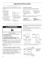
instructions pour I'installation darts un placard
ou un encastrement
Ce seche-linge peut _tre installe dans un placard ou un
encastrement. Ce seche-tinge ne dolt pas 6tre instatte derrri_re
une porte verrouillable, coulissante, ou une porte avec charni_re
du c6te oppose de I'emplacement de celle du s_che-linge.
Les distances de separation sont exprimees en miltim_tres;
il s'agit des distances minimales. II est utile de prevoir des
distances de separation superieures pour facititer l'instatlation
et les travaux d'entretien, ou si ceci est exige par les codes
et r_glements Iocaux.
Si la porte du placard est instaltee, on dolt respecter la taille
minimale des ouvertures d'entree d'air au sommet et en bas.
On peut utitiser une porte h claire-vole offrant une surface de
passage d'air equivatente.
Le circuit d'evacuation du seche-linge dolt _tre retie h l'exterieur.
Aucun appareit utilisant un combustible ne dolt _tre instatte dans
le m_me placard.
Distances de s_paration minimales
381 mm
05")
o o
C_
I I
LJ
riqrii-b..
0 mm _ 0 mm
(o") _ (o")
.........II......
Encastrement, vue avant
356 mm
(14") max
Portedu
placard
d
(1
'' _ 0ram
(0")
_1 1_25 mm 11")
Placard, vue laterale
On doit pr_voir un espacement additionnel pour tenir compte _ventuellement
des moulures du mur, de la porte et du plancher, ou si le circuit d'_vacuation
comporte un coude.
Portedu
placard
(48in._)
vue
avant O
(24in._)
L
76 ram (3")
+
* Taille minimale de
I'ouverture pour la porte
du placard, On peut
utiliser une porte h
claire-vole offrant une
surface de passage
d'air _quivalente.
76 mm (3")
17

Dimensions du produit = S_che-linge
de 686 mm (27")
965 mm
(3_ _")
_r
+
25 mm
(1")
686 mm
(27':)
{
VUE AVANT
CABLE
ELECTRIQUE
102mm (4")
dia.
b358 mm_
04")
VUE ARRIERE
t
715 mrn
+
203 mm
(8")
921 mm
(36[/4")
25 mm
(1")
736 mm
, (29) 695 mm
_ i (27V4")
/
VUE LATE_RALE
Ce seche-linge est livr_ sans cordon d'alimentation etectrique et
sans prise. II dolt _tre raccorde par un electricien competent
une source d'alimentation electrique monophasee, de tension
tette qu'indiquee sur la plaque signal_tique en utilisant un
c&btage fixe approprie, conformement aux r_glements Iocaux
et nationaux.
[] Un cordon circulaire & 3 ills avec des conducteurs d'au moins
2,5 mm2 de section dolt _tre utilis&
[] Un fusible de 30A dolt _tre utilise sur l'alimentation et un
sectionneur bipolaire sur tes deux lignes dolt _tre incorpor_
dans le c&btage fixe pour assurer une deconnexion totale
en cas de survoltage de categorie III, conformement aux
r_glements Iocaux en mati_re de raccordement. Le s_che-
linge dolt _tre place de fa(_on &ce que le sectionneur soit
facile d'acc_s pour I'utilisateur.
[] Une garniture de serre-fil pour le d'alimentation est fournie
avec le seche-linge et dolt _tre settee une fois le c&btage
termin& Les bomes de raccordement au secteur se trouvent
derriere le petit panneau d'acc_s arri_re (couvercle du bottler
de connexion), et les connexions doivent _tre reatisees
conformement au marquage des bomes. Ne pas oublier de
remettre en place le panneau d'acc_s du bottler de connexion
(couvercte du bottler de connexion).
REMARQUE : Conformement & la directive europeenne
CEM (2004/108/EC), I'impedance maximate du syst_me
d'alimentation electrique auquet le s_che-linge electrique
dolt _tre connecte est de 0,29 Ohm + j0,18 Ohm.
Risque de choc _lectrique
Cet appareil est un s_che=linge a 3 conducteurs
qui dolt 6tre reli_ _ la terre.
Ne pas utiliser une tuyauterie de gaz pour le
raccordement & la terre.
Le non=respect de ces instructions peut causer
un d_c_s, un incendie ou des blessures graves.
Si les codes le permettent et si un conducteur supplementaire
de mise & ta terre est utitise, il est recommande qu'un electricien
quatifie inspecte le parcours du fil de mise & la terre.
Methode recommand_e pour la raise _ la terre
[]
It incombe & l'utilisateur de contacter un electricien qualifie
afin de veilter & ce que I'instaltation electrique soit r_alisee de
fa(_on adequate et en conformite avec les exigences de tous
les codes et r_glements Iocaux.
18

Risque d'Jncendie
UtitJser un conduit d'_vacuation en m_tal tourd.
Ne pas utiliser un conduit d'_vacuation en plastique.
Ne pas utJliser un conduit d'_vacuation en feuJlle
de m_tal.
Le non=respect de ces instructions peut causer
un d_c_s ou un Jncendie.
AVERTISSEMENT : Pour r6duire le risque d'incendie,
ce s6che-linge DOlT I_VACUER L'AIR A L'EXTERIEUR.
[] Une aeration adequate est necessaire pour eviter le retour des
gaz dans la piece en provenance d'appareits menagers qui
utitisent d'autres carburants comme combustible, y compris
les feux ouverts (autrement dit le debit d'air entrant dans la
piece dolt _tre egat au debit qui en sort).
[] L'event du s_che-linge ne dolt pas _tre connecte & un conduit
d'evacuation de gaz, une cheminee, un mur, un plafond ou un
vide de construction, ou tout autre conduit utitise pour
I'evacuation.
[] Ne pas utitiser un ctapet d'evacuation A fermeture
magn_tique.
[] Ne pas installer le conduit m6tatlique flexible dans les cavites
fermees des murs, plafonds ou planchers.
[] Utiliser un conduit d'evacuation en metal Iourd de 102 mm
(4") et des brides de fixation.
[] Utitiser des brides de fixation pour sceller tousles joints.
L'event ne dolt pas _tre connecte ou fixe avec des vis ou
autres dispositifs d'accrochage qui se prolongent A l'interieur
de I'event et peuvent retenir les peluches. Ne pas utitiser
de ruban adhesif en toite.
IMPORTANT : Respecter les dispositions de tousles codes
et r_glements en vigueur.
Utiliser un conduit d'evacuation en metat lourd. Ne pas utitiser
un conduit de plastique ou en feuitle metattique.
On recommande d'utiliser un conduit metattique rigide pour
r_duire les risques d'ecrasement et de deformation.
Un conduit m6tallique flexible dolt _tre totalement deptoye et
soutenu Iorsque le s_che-linge est &sa position finale. Enlever
tout exc_s de conduit flexible pour eviter tout affaissement/
deformation qui r_duira ledebit d'air et le rendement du
s_che-linge.
Terminer le conduit d'evacuation par un ctapet de decharge
pour eviter les rongeurs et insectes d'entrer dans le bAtiment.
Le clapet de decharge dolt _tre situe & au moins 305 mm (12")
au-dessus du sol ou de tout autre objet susceptible de se trouver
sur le trajet de I'air humide rejete (par exempte, fleurs, roches ou
arbustes).
Lots de rutilisation d'un circuit d'evacuation existant, nettoyer les
peluches sur toute la Iongueur du syst_me et veiller & ce que la
bouche de decharge ne soit pas obstruee par une accumulation
de peluches. Remplacer tout conduit de plastique ou de feuille
metattique mince par un conduit metallique flexible ou rigide.
Planifier l'instaltation pour introduire le nombre minimal de coudes
et de changements de direction.
D_bitd'_vacuation
A. Bend#bitd'#vacuation
B.Meilleurd#bitd'#vacuation
Si des coudes sont utilises ou des changements de direction
effectues, pr_voir autant d'espace que possible. Plier le conduit
graduellement pour eviter de le deformer.
La bouche de sortie est situee & I'arri_re du seche-linge, en
bas/au centre.
On peut acheminer le conduit d'evacuation par le haut, par te
bas, par ta gauche, par la droite, derriere le seche-tinge ou en
ligne droite depuis I'arri_re du s_che-linge.
Longueur du circuit d'_vacuation
La longueur maximale du circuit d'evacuation depend du type de
conduit utitise, du nombre de coudes et du type de bouche de
decharge.
Longueur maxJmale du conduit
Clapet de decharge de 102 mm (4")
Typebofte Apersiennes Inclin#de64mm(21/_")
coo .t
metallique rigide
t t t
Nombre d'angles Clapets de type bofte et Clapet inclin_
9 39,6 m (130 pi.) 39,3 m (129 pi.)
1 38,1 m (125 pi.) 36,3 m (119 pi.)
2 35,1 m (115 pi.) 33,2 m (199 pi.)
3 32,3 m (106 pi.) 30,5 m (100 pi.)
4 98 m (98 pi.) 28 m (92 pi.)
Si le seche-linge est instalte dans un espace reduit tel qu'une
chambre & coucher, une salte de bain ou un placard, on dolt
prevoir une arrivee d'air en quantite suffisante pour la combustion
et la ventilation. (Consulter les codes et r_glements en vigueur.)
Voir "Instructions pour I'installation dans un placard ou dans
un encastrement" de la section "Exigences d'emptacement'.
Uemploi d'une bouche de decharge de 102 mm (4") est
preferable. On peut cependant utiliser une bouche de 64 mm
(2_A"). Une bouche de decharge de 64 mm (2W') peut causer
une plus forte retropression que les autres genres de bouches.
Pour une installation permanente, un syst_me d'evacuation
fixe est requis.
19

I_vacuation multiple du s_che-linge
[] Un conduit d'evacuation principal peut _tre utilise pour un
groupe des s_che-linge. Le conduit d'evacuation principal
devrait _tre d'un diam_tre suffisant pour evacuer 5663 I/min
(200 pP/min) d'air par s_che-linge. Des fittres & peluches
de forte capacite et de conception adequate peuvent _tre
utitises dans le conduit principal d'evacuation s'ils sont
inspectes et nettoyes fr6quemment. La piece oQ se trouvent
les seche-linge devrait recevoir un apport d'air de debit egat
ou superieur au debit total (pi3/min) de debit de tous
les seche-linge instatles dans la piece.
[] Un ensemble antirefoulement est necessaire et est fourni
par un distributeur de buanderie commercial et devrait _tre
instatle dans leconduit d'evacuation de chaque seche-tinge
pour eviter rair evacu6 de retourner dans les s_che-linge
et pour maintenir une pression equitibr6e dans le conduit
principal d'evacuation. Des orifices de passage d'air
de retour non obstrues sont requis.
Chaque conduit d'evacuation devrait pen6trer dans leconduit
principal &un angle pointant dans la direction du debit d'air.
Les conduits raccordes au conduit principal de part et d'autre
devraient _tre disposes en quinconce pour que I'air evacu6
par un seche-linge ne puisse perturber revacuation d'un autre
seche-linge.
Uangle maximal entre le conduit connecte _ un s_che-tinge
et le conduit principal ne devrait pas depasser 30°.
A. Conduitindividueld'#vacuationdus#che-Iinge
B.Conduitprincipald'#vacuation
Faire en sorte que les vapeurs gen6r6es par les tiquides de
nettoyage _ sec ne puissent pas atteindre les orifices d'entree
d'air; ces vapeurs creent des composes acides qui, Iorsqu'ils
sont attir6s vers les unites de chauffage des s_che-linge, peuvent
endommager les seche-linge et le linge en cours de sechage.
Une bouche de nettoyage devrait _tre instaltee dans le conduit
principal d'evacuation pour les nettoyages periodiques du
syst_me d'evacuation.
Si une bouche de d_charge ne peut _tre utilis_e :
A. Bouche de d#charge
ou coude de d#viation
B. Mur
C. Chemin#e principale
de mise a I'air Iibre
D. Conduit horizontal
E. Coude de d#viation
180°
F. Conduit vertical
G. Toit
t
610mm(2pi)
min.au-dessus
dupoint le
plus_lev_
dub&timent
i 300 mm (121') min. au-dessus
de toute accumulation de
neige, gtace ou debris
comme des feuittes.
G
C
Uextremite exterieure du conduit principal devrait _tre munie d'un
coude de deviation dirige vers le bas. Si le conduit principal suit
une trajectoire verticate _ travers le toit, plut6t qu'& travers lemur,
installer un coude de deviation de 180° & l'extr6mite du conduit et
depassant d'au moins 610 mm (2 pi) au-dessus de la partie la
plus elevee du b&timent. Uouverture murale ou dans le toit dolt
avoir un diam_tre superieur de 13 mm (1A")_ cetui du conduit
d'evacuation. Le conduit d'evacuation devrait _tre centr_
dans I'ouverture.
Ne pas installer une grille ou un couvercle sur I'extr_mite
du conduit d'evacuation.
2O
La page est en cours de chargement...
La page est en cours de chargement...
La page est en cours de chargement...
La page est en cours de chargement...
La page est en cours de chargement...
La page est en cours de chargement...
La page est en cours de chargement...
La page est en cours de chargement...
La page est en cours de chargement...
La page est en cours de chargement...
La page est en cours de chargement...
La page est en cours de chargement...
La page est en cours de chargement...
La page est en cours de chargement...
La page est en cours de chargement...
La page est en cours de chargement...
La page est en cours de chargement...
La page est en cours de chargement...
La page est en cours de chargement...
La page est en cours de chargement...
La page est en cours de chargement...
La page est en cours de chargement...
La page est en cours de chargement...
La page est en cours de chargement...
La page est en cours de chargement...
La page est en cours de chargement...
La page est en cours de chargement...
La page est en cours de chargement...
La page est en cours de chargement...
La page est en cours de chargement...
La page est en cours de chargement...
La page est en cours de chargement...
La page est en cours de chargement...
La page est en cours de chargement...
La page est en cours de chargement...
La page est en cours de chargement...
-
 1
1
-
 2
2
-
 3
3
-
 4
4
-
 5
5
-
 6
6
-
 7
7
-
 8
8
-
 9
9
-
 10
10
-
 11
11
-
 12
12
-
 13
13
-
 14
14
-
 15
15
-
 16
16
-
 17
17
-
 18
18
-
 19
19
-
 20
20
-
 21
21
-
 22
22
-
 23
23
-
 24
24
-
 25
25
-
 26
26
-
 27
27
-
 28
28
-
 29
29
-
 30
30
-
 31
31
-
 32
32
-
 33
33
-
 34
34
-
 35
35
-
 36
36
-
 37
37
-
 38
38
-
 39
39
-
 40
40
-
 41
41
-
 42
42
-
 43
43
-
 44
44
-
 45
45
-
 46
46
-
 47
47
-
 48
48
-
 49
49
-
 50
50
-
 51
51
-
 52
52
-
 53
53
-
 54
54
-
 55
55
-
 56
56


Maytag MDE22PD Installation Instructions Manual
- Catégorie
- Sèche-linge électriques
- Taper
- Installation Instructions Manual
- Ce manuel convient également à
dans d''autres langues
- italiano: Maytag MDE22PD
- English: Maytag MDE22PD
- español: Maytag MDE22PD
Documents connexes
-
Maytag MDG25PNAGW0 Installation Instructions Manual
-
-
-
-
-
-
