Manhattan Comfort Eiffel Garage Work Station Set of 2 Assembly Manual
- Taper
- Assembly Manual

Ed. 001, 2022/06 - Manhattan Comfort.
888-230-2225
help@manhattancomfort.com
Model # 252BMC6, 252BMC8, 252BMC83, 252BMC84, 252BMC85
26
lb
Eiffel 28.35 Mobile Cabinet
Mobile Cabinet with 2 doors and 1 drawer
Armoire mobile avec 2 portes et 1 tiroir
The indicated values consider static weights and evenly distributed over the parts.
Les valeurs indiquées tiennent compte des poids statiques et uniformément répartis sur les pièces.
15
lb
20
lb
15
lb

n.° ID
2
01
02
03
04
05
1
1
1
06 2
07 1
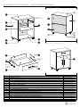
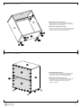
INCLUDED IN THE PACKAGE / INCLUS DANS LE PACKAGE
Parts identification (Description) / Identification des pièces (Description) Quantity / Quantité
Left Side Panel / Panneau latéral gauche
Door / Porte
REAR VIEW / VUE ARRIÈRE
FRONT VIEW - FINAL APPEARANCE
VUE DE FACE - APPARENCE FINALE
05
02
14
01
10
12
03
Base / Base
Back Panel / Panneau arrière
1
1
Removable Shelf / Étagère amovible
08 2
Crossbar / Traverse
Plastic "H" Profile 667mm / Profilé en "H" en plastique 667mm
1
Right Side Panel / Panneau latéral droit
Top Panel / Panneau du haut
1
1
1
1
Front of the drawer / Devant du tiroir
Left Side Panel of the drawer / Panneau latéral gauche du tiroir
Rear Panel of the drawer / Panneau arrière du tiroir
Base of the drawer / Base du tiroir
1
Right Side Panel of the drawer / Panneau latéral droit du tiroir
09
10
11
12
13
1
14
15
2
16
Metallic slide
Glissière
métallique
Caster RIS 50 PL ZB, without lock / Roulettes RIS 50 PL, pas de blocage
2
Caster RIS 50 PL TR, with lock / Roulettes RIS 50 PL, avec blocage
02
04
05
06
06
07
08
09
11
13
06
06
04
Metallic slide
Glissière métallique
Metallic slide
Glissière
métallique
16
15
15
16 15
16

3
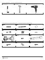
18x
A8x
B4x
C
INCLUDED IN THE HARDWARE / INCLUS DANS LE MATÉRIEL
TOOLS NEEDED / OUTILS NÉCESSAIRES
6x
D6x
E38x
F
4x
G28x
H3x
I
6x
J4x
K16x
L
Simple hammer.
Marteau simple.
Manual screwdriver.
Tournevis manuel.
Electric screwdriver with phillips tips.
Tournevis électrique avec pointes phillips.

4
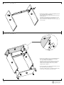
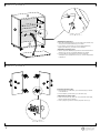
STEP 2 / ÉTAPE 2
STEP 1 / ÉTAPE 1
DETAIL 1 / DÉTAIL 1
!
• Connect the Crossbar (01) to the Side Panels (02) and
(03) with dowels (A) and bolts (B).
At the end of the fixing, apply the adhesive covers (C)
on the bolts (B).
Connectez le Traverse (01) sur les Panneaux latéraux
(02) et (03) des chevilles (A) et des vis (B).
A la fin de la fixation, appliquez couvercles adhésifs (C)
sur les vis (B).
01
03
04
05
01
02
02
03
05
03
• Connect the Top Panel (05) over the Side Panels (02)
and (03) with dowels (A) and cam lock hardware
(D + E), as shown in the DETAIL 1.
Connectez le Panneau du haut (05) sur les Panneaux
latéraux (02) et (03) avec les chevilles (A) et du
matériel de verrouillage à came (D + E), comme
indiquée dans le DÉTAIL 1.
• Connect the Base (04) under the Side Panels (02) and
(03) with dowels (A) and bolts (B).
Connectez la Base (04) sur les Panneaux latéraux (02)
et (03) avec des chevilles (A) et des vis (B).

STEP 4 / ÉTAPE 4
STEP 3 / ÉTAPE 3
!
5
Fixing the Back Panels (06):
• Fix the Back Panels (06) by fitting the plastic profile
(14) at the junction between the two parts and
applying the nails (F) in the indicated positions.
Fixation des Panneaux arrière (06):
• Fixez les Panneaux arrière (06) en insérant le Profilé
en plastique (14) dans la couture entre les deux
pièces et en appliquant les clous (F) dans les
positions indiquées.
03
04
05
01
02
Fixing the casters (15) and (16):
• Fix the casters (15) and (16) under the Base (04)
with the bolts (L), in the positions shown in drawing.
Apply four bolts (L) to each caster .
Fixation des roulettes (15) et (16):
• Fixez les roulettes (15) et (16) sous la Base (04) avec
les vis (L), dans les positions indiquées sur le dessin.
Appliquer quatre vis (L) sur chaque roulette.
15
16
15
16
14
16
16
15
06
04
02
05
06

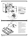
Installing the Shelf (07):
• Insert the metal brackets (K) into the holes in the Panels (02)
and (03) and install the Shelf (07) over them.
• If you prefer, fix the Shelf (07) on the metal brackets (K)
applying the bolts (H), as shown in the DETAIL 2.
Installation de Étagère (07):
• Insérez supports métalliques (K) dans les trous des Panneaux
latéraux (02) et (03) et installez l'Étagère (07) dessus.
• Si vous préférez, fixez l'Étagère (07) sur les supports
métaliques (K) en appliquant les vis (H), comme indiqué dans
le DÉTAIL 2.
STEP 6 / ÉTAPE 6
STEP 5 / ÉTAPE 5
!
04
02
6
DETAIL 2 / DÉTAIL 2
DETAIL 3 / DÉTAIL 3
03
05
07
03
07
Preparing the Doors (08):
• Fix the hinges (G) with bolts (H) in the Doors (08), as shown
in the DETAIL 3.
• Fix the handles (I) with bolts (J) in the Doors (08).
Préparation des Portes (08):
• Fixez les charnières (G) avec les vis (H) dans les Portes (08),
comme indiqué dans le DÉTAIL 3.
• Fixez la poignée (I) dans les Portes (08) avec des vis (J).
08 08

STEP 8 / ÉTAPE 8
STEP 7 / ÉTAPE 7
Fixer and adjustment bolts.
Vis de fixation et réglage.
Installing the Doors (08):
• Fix the hinges connectors (G) of the Doors (08)
on the Side Panels (02) and (03) with bolts (H),
taking the markings in these Panels (02) and
(03) as a reference for correct positioning.
The hinge and its connector includes two more
bolts, shown in DETAIL 4. Use these fixer and
adjustment bolts to tighten, adjust and align
the doors.
Installation des Portes (08):
• Fixez les connecteurs des charnières (G) des
Portes (08) sur les Panneaux latéraux (02) et
(03) avec des vis (H), en prenant les marques
comme référence pour positionnement correct.
La charnière et son connecteur comprennent
deux autres vis, illustrées dans le DÉTAIL 4.
Utilisez ces vis de fixation et réglage pour
serrer, régler et aligner les portes.
09
DETAIL 4
DÉTAIL 4
02
05
03
08
08
07
04
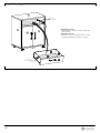
Preparing the drawer:
• Fix the handle (I) with bolts (J) in the Front of
the drawer (09).
• Connect the parts (09), (10), and (11) with the
dowels (A) and cam lock hardware (D + E), as
shown in DETAIL 5. Apply adhesive covers (C).
• Connect the parts (10), (11) and (12) with the
dowels (A) and bolts 5,0 x 50mm (B).
• Insert the Base of the drawer (13) into the
channel in the Side Panels (10) and (11) and
in the Front of the drawer (09), and fix it at the
lower edge of the Rear Panel of the drawer (12)
with nails (F).
Préparation du tiroir:
• Fixez la poignée (I) dans le Devant du tiroir (09)
avec des vis (J).
• Connectez les pièces (09), (10) et (12) avec
les chevilles (A) et le matériel de verrouillage à
came (D+E), comme indiqué dans le DÉTAIL 5.
Appliquez les couvercles adhésifs (C).
• Connectez les pièces (10), (11) et (12) avec
les chevilles (A) et des vis 5,0 x 50mm (B).
• Insérer la Base du tiroir (13) dans le canal des
Panneaux latéraux (10) et (11) et dans la
Devant du tiroir (09) et le fixer au du bord
inférieur du Panneau arrière du tiroir (12) avec
des clous (F).
Metallic slide
Glissière métallique
10
11
12
13
09
10
7
DETAIL 5
DÉTAIL 5

STEP 9 / ÉTAPE 9
!
02
8
03
09
Installing the drawer:
• Install the drawer, fitting it so that the metal slides
slide smoothly.
Installation du tiroir:
• Installez le tiroir en l'ajustant de manière à ce que
les glissières métalliques coulissent en douceur.
10
11
12
13
Metallic slide
Glissière métallique
Metallic slide
Glissière métallique
05
01
08
08
04

Ed. 001, 2022/06 - Manhattan Comfort.
888-230-2225
help@manhattancomfort.com
Model # 253BMC6, 253BMC8, 253BMC83, 253BMC84, 253BMC85
44
lb
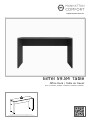
Eiffel 59.84 Table
Office Desk / Table de travail
The indicated value consider static weight and evenly distributed over the part.
Les valeur indiquée tiennent compte des poid statique et uniformément répartis sur le pièce.

n.° ID
2
01
02
03
04 1
1
1
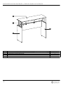
INCLUDED IN THE PACKAGE / INCLUS DANS LE PACKAGE
Parts identification (Description) / Identification des pièces (Description) Quantity / Quantité
Top Panel / Panneau du haut
Back Panel / Panneau arrière
Left Side Panel / Panneau latéral gauche
01
02
03
04
1
Right Side Panel / Panneau latéral droit

3
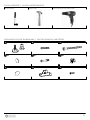
4x
A8x
B4x
C
INCLUDED IN THE HARDWARE / INCLUS DANS LE MATÉRIEL
Simple hammer.
Marteau simple.
Manual screwdriver.
Tournevis manuel.
Electric screwdriver with phillips tips.
Tournevis électrique avec pointes phillips.
TOOLS NEEDED / OUTILS NÉCESSAIRES
4x
D6x
E6x
F
6x
G2x
H6x
I

4
02
01
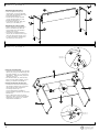
STEP 2 / ÉTAPE 2
Assembling the table frame:
• Insert the plastic bushing and
leveling base (A) into the indicated
holes under the Left Side Panel (02)
and Right Side Panel (03).
• Conect the Side Panels (02) and
(03) to the Back Panel (01) with
dowels (B) and bolts (C).
At the end of the fixing, apply the
covers (D) on the bolts (C).
Assemblage du cadre de table:
• Insérez la douille en plastique et la
base de nivellement (A) dans les
trous indiqués sous les Panneaux
latéraux (02) et (03).
• Connectez les Panneaux latéraux
(02) et (03) au Panneau arrière (01)
avec des chevilles (B) et des vis (C).
A la fin de la fixation, appliquez les
couvercles (D) sur les vis (C).
STEP 1 / ÉTAPE 1
04
03
01
02
03
Fixing the Top Panel (04):
• Connect the Top Panel (04) over the Side
Panels (02) and (03) with dowels (B) and
cam lock hardware (E + F), as shown in
the DETAIL 1. After the fixing, apply the
adhesive covers (G).
• Fix the Back Panel (01) under the Top
Panel (04) with metal brackets (H) and
bolts (I), as shown in the DETAIL 2.
Fixation du Panneau du haut (04):
• Connectez le Panneau du haut (04) sur
les Panneaux latéraux (02) et (03) avec
les chevilles (B) et du matériel de
verrouillage à came (E + F),
commé indiquée dans le DÉTAIL 1.
Après la fixation, appliquez les couvercles
adhésifs (G).
• Fixez le Panneau arrière (01) sous le
Panneau du haut (04) avec des supports
métalliques (H) et des vis (I), comme
indiquée dans le DÉTAIL 2.
DETAIL 1
DÉTAIL 1
DETAIL 2
DÉTAIL 2
04
03
04
01
-
 1
1
-
 2
2
-
 3
3
-
 4
4
-
 5
5
-
 6
6
-
 7
7
-
 8
8
-
 9
9
-
 10
10
-
 11
11
-
 12
12


