Maico PEH series Mounting Instructions And Directions For Use
- Taper
- Mounting Instructions And Directions For Use

Änderungen vorbehalten! / Subject to change! / Sous réserve de modifications!
Heizlüfter PEH.../PDH...
Electric Air Heaters PEH.../ PDH...
Réchauffeur d'air électrique PEH.../PDH...
Montage- und Gebrauchsanweisung
Mounting instructions and directions for use
Instructions de montage et mode d'emploi


Wichtige Hinweise
.
D
Achtung: Während des Betriebs besteht Verbren-
nungsgefahr durch heiße Oberflächen. Heizstäbe
nicht anfassen.
l Die Anschlußleitung ist zeitweise auf Defektheit zu
kontrollieren.
l Anschlußleitung nicht über das Ausblasgitter füh-
ren.
l Anschlußleitung nicht über scharfe Kanten ziehen
oder einklemmen.
l Den Stecker nie an der Anschlußleitung aus der
Steckdose ziehen.
l Gerät darf nicht unbeaufsichtigt von Kindern, alten
oder gebrechlichen Personen bedient werden.
l Heizlüfter nicht abdecken, da erhöhte Brandgefahr
durch Wärmestau entsteht.
l Heizkörper sind gegen thermische Überlastung
gesichert und schalten automatisch ab.
• Vorgehensweise im Störungsfall:
- Stecker ziehen.
- Störursache feststellen und beseitigen.
- Bei PEH 3-PDH 15 Resetknopf [4] drücken.
- Bei PDH 20 Gehäusedeckel abnehmen und
Resetknopf [5] drücken.
• Es dürfen sich keine entflammbaren Gegenstän-
de in unmittelbarer Nähe des Gerätes befinden.
• Heizlüfter darf nicht unmittelbar unter einer
Wandsteckdose montiert werden.
• Heizlüfter ist nicht in unmittelbarer Umgebung
eines Bades oder eines Schwimmbeckens zu
verwenden.
• Heizlüfter nicht in Räumen mit einer Bodenfläche
kleiner 4m² verwenden.
l Zur zeitweisen oder dauerhaften Beheizung von
Industrieräumen, Werkstätten, Lager, Versammlungs-
räumen, Verkaufs- und Ausstellungsräumen, Büros,
Gärtnereien, Garagen.
l Zur Trocknung feuchter Räume, wie Baustellen,
Kellerräume usw.
l Bestimmungsgemäße Verwendung: MAICO haftet
nicht für Schäden, die durch bestimmungswidrigen
Gebrauch verursacht werden.
l Der Heizlüfter darf nur mit der Bemessungsspan-
nung betrieben werden, die auf dem Typenschild
angegeben ist.
l Reparaturen dürfen nur von Elektrofachkräften
durchgeführt werden.
• Die Bauart des Heizlüfters entspricht den sicher-
heitstechnischen Anforderungen des VDE im Rah-
men des Gerätesicherheitsgesetzes sowie den
einschlägigen Bestimmungen der EG-Richtlinien.
Sicherheitshinweise
Elektrischer Anschluss
•Serienmäßig mit Anschlußleitung für alle Typen.
•Steckverbindung mit Schutzkontaktstecker für Typ
PEH 3.
• Steckverbindung mit CEE-Stecker bis 16 A, für die
Typen PDH 5 und PDH 9.
•Steckverbindung mit CEE-Stecker bis 32 A, für die
Typen PDH 15 und PDH 20.
Verwendungszweck
Montage der Wandhalterung PDHW
(Zubehör)
Achtung: Bei Wandmontage darf der Heizlüfter nicht
von der Badewanne oder der Dusche aus erreich-
bar sein.
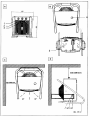
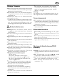
l Bei Wandmontage sind die in Abb. C und D
eingetragenen Abstandsmaße einzuhalten.
l Bei der Wandmontage beträgt der Mindestab-
stand vom Heizlüfter zur Bodenfläche 1.8 m.
l Nach Montage des Gerätes muß der Stecker
zugänglich sein.
• Der Heizlüfter ist wartungsfrei. Es empfiehlt
sich jedoch den Ventilator und das Ansaug-
gitter auf Verschmutzung zu prüfen und bei
Bedarf zu reinigen.
Achtung:
Der Heizlüfter darf im transportablen Betrieb nur mit
dem angeschraubten Rohrstativ betrieben werden.

Wandmontage
l Bei der Wandhalterung werden vier Schrauben
(PDHW 3-15, M6x20; PDHW 20, M8x25) für die
Befestigung am Gehäuse, sowie 4 Blindstopfen
mitgeliefert. Zusätzlich werden bauseits zwei Trag-
schrauben für die Wandbefestigung (PDHW 3-15,
∅ 7mm; PDHW 20, ∅ 8mm) und eine Fixierschrau-
be (∅ 9mm) benötigt.
l Die Wandhalterung an der Wand mit den zwei
Tragschrauben befestigen. Die Fixierschraube
dient dazu die Montage und das Ausrichten zu
erleichtern.
l Das Rohrstativ am Heizlüfter abschrauben.
l Eine mitgelieferte Schraube jeweils in das oberste
Gewindeloch auf jeder Gehäuseseite einschrau-
ben.
l Das Gerät auf den Schrauben gestützt in der
Wandhalterung einhängen.
l Mit den letzten zwei Schrauben das Gehäuse in
einer der drei Vertikalpositionen befestigen.
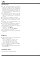
•Die Wandmontage des Heizlüfters ist in folgenden
Neigungswinkeln möglich:
- Horizontal +/- 30° (Abb C)
- Vertikal 7.5°, 15° nach unten (Abb. D)
•Alle 4 Schrauben fest anziehen.
•Die 4 Blindstopfen in die übrigen Schraubenlöcher
einstecken.
Bedienung
l Ventilator und Heizung sind mit dem Drehschalter
[2] in 4 Stufen schaltbar:
- Stufe 1: Heizung -Aus-, Ventilator 100%
- Stufe 2: Heizung 50%, Ventilator 50%
- Stufe 3: Heizung 50%, Ventilator 100%
- Stufe 4: Heizung 100%, Ventilator 100%
•Stufenlos einstellbarer Heizungsthermostat [1] 4-
40°C, Schaltdifferenz ca. 2K.
•Zeitschaltuhr [3] mit bis zu 24 Stunden vorwählbarem
Einschaltzeitpunkt.
Technische Daten
Siehe Typenschild bzw. gültigen Katalog
D

Important notes
• For the temporary or continuous heating of industrially
used rooms, workshops, warehouses, assembly
rooms, sales showrooms and exhibition areas,
offices, garden centres and garages.
• For drying humid rooms such as building sites,
cellars and basements etc.
l Authorised use: MAICO will not be held responsible
for damage caused by unauthorised use.
l The electric air heater may only be used at the rated
voltage indicated on the rating plate.
•Repairs may only be carried out by suitably qualified
personnel.
•The electric air heater is designed in accordance
with VDE safety requirements within the scope of
the Appliance Safety Act and the valid stipulations
of the EC directives.
Electrical connection
•Use a connecting cable as standard for the
connection of all models.
•Plug-in connection with grounded plug for model
PEH 3.
• Plug-in connection with CEE plug up to 16 A for
models PDH 5 and PDH 9.
•Plug-in connection with CEE plug up to 32 A for
models PDH 15 and PDH 20.
Mounting of the wall holder PDHW
(accessories)
Note: When wall mounting, the air heater must not be
positioned within reach of the bath or shower.
l When wall mounting, observe the distance
measurements given in Fig. C and D.
l When wall mounting, the minimum distance from the
air heater to the floor surface is 1.8 m.
•Wall mounting of the air heater is possible at the
following angles of inclination:
- Horizontally +/- 30° (Fig. C)
- Vertically 7.5°, 15° downwards (Fig. D)
•In order to fix the vertial angle of inclination of the air
heater,screw the self-tapping screws into the
prepared blind holds in the housing.
l After mounting the device, the plug must be
accessible.
Intended application
GB
Note: During operation, skin burns can be incurred by
contact with hot surfaces. Do not touch the heating
rods.
l The connecting cable must be periodically checked
for defects.
l Do not lay the connecting lead across the outlet
grille.
l Do not pull or jam the connecting lead over sharp
edges.
l Never remove the plug from the socket by pulling
the connecting lead.
l The device may not be operated by children,
elderly or frail persons without adequate
supervision.
• Do not cover the air heater, as this increases the risk
of fire due to the build-up of heat.
• The heating elements are safeguarded against
thermal overload and cut out automatically.
• Procedure in case of failure:
- Switch off the power.
- Ascertain the cause of the failure and remedy.
- With the PEH 3-PDH 15, press the reset button [4].
- With the PDH20, remove the housing lid and press
the reset button [5].
• Ensure that there are no inflammable objects
positioned in the immediate vicinity of the device.
• The air heater must not be mounted directly
underneath a wall socket.
• The air heater must not be used in the immediate
vicinity of a bathroom or swimming pool.
• Do not use the air heater in rooms with a floor
area smaller than 4 sq. metres.
Safety remarks
l The air heater is maintenance-free. However,
we recommend checking the fan and the
intake grill for dirt and removing if necessary.
Note:
The air heater may only be used in conjunction with
the screwed-on tubular stand when in mobile opera-
tion.

Operation
l The fan and heater can be switched to 5 setting
steps using rotary switch [2]:
- Step 1: Heating off, fan 100%
- Step 2: Heating 50%, fan 50%
- Step 3: Heating 50%, fan 100%
- Step 4: Heating 100%, fan 100%
•Steplessly adjustable heating thermostat [1]
4-40°C, hysteresis appr. 2K.
•Time switch [3] with cut-in time selectable up to
24 hours in advance.
See rating plate / valid catalogue.
Specifications
GB
Wall mounting
With the wall holder four screws
(PDHW 3-15, M6x20; PDHW 20, M8x25) are pro-
vided for fixture to the housing, as well as 4 dummy
plugs. In addition, two bearing screws must be
provided by the customer for wall fixing (PDHW 3-
15, dia. 7 mm; PDHW 20, dia. 8 mm) as well as a
fixing screw (dia. 9 mm).
l Fasten the wall retainer on the wall using the two
bearing screws. The fixing screw is required to
simplify mounting and alignment.
l Unscrew the tubular stand on the air heater.
l Screw one of the supplied screws into a threaded
hole on each side of the housing.
l Suspend the unit in the wall retainer, supported by
the screws.
l Using the last two screws, fasten the housing in
one of the three vertical positions.
•Wall mounting of the air heater is possible at any
of the following angles of inclination:
- Horizontally +/- 30° (Fig. C)
- Vertically 7.5°, 15° downwards (Fig. D)
•Tighten all four screws.
•Insert the 4 dummy plugs into the remaining screw
holes.

F
.
Remarques importantes
Attention: risque de brûlure lorsque lappareil est en
marche car les surfaces sont très chaudes. Eviter
de toucher les corps chauffants.
l Contrôler le câble de raccordement périodiquement
pour voir sil est endommagé.
l Ne pas guider le câble de raccordement au-dessus
de la grille dévacuation dair.
l Ne jamais tirer ou pincer le câble de raccordement
sur des arêtes vives.
l Ne jamais tirer sur le câble de raccordement pour
débrancher la fiche de la prise .
l Défense de laisser lappareil à la portée des
enfants, des personnes âgées ou infirmes.
• Ne pas recouvrir le réchauffeur dair car
laccumulation de chaleur augmente le risque
dincendie.
• Les éléments de chauffage sont dotés dune
protection thermique contre les surcharges et
sarrêtent automatiquement.
• Procédure à suivre en cas de panne:
- Mettre lappareil hors tension.
- Rechercher la cause de lanomalie et léliminer.
- Sur les modèles PEH 3 PDH 15, appuyer sur la
touche Reset [4] dans le couvercle de la boîte de
jonction.
- Sur le modèle PDH 20, ôter le couvercle du boîtier
et appuyer sur la touche Reset [5].
• Aucun objet inflammable ne doit se trouver à
proximité directe de lappareil.
• Le réchauffeur dair ne doit pas être monté
directement sous une prise encastrée.
• Le réchauffeur dair ne doit pas être utilisé à
proximité directe dune baignoire ou dune piscine.
• Pour chauffage temporaire ou permanent de locaux
industriels, ateliers, entrepôts, salles de réunion,
bureaux de vente et salles dexposition, bureaux,
jardineries et garages.
• Pour séchage de locaux humides, chantiers, caves
etc.
•Utilisation conforme aux dispositions: MAICO
nassume aucune responsabilité pour les
dommages résultant dune utilisation contraire
aux dispositions.
l Le réchauffeur dair ne doit être exploité quà la
tension de calcul indiquée sur la plaque
signalétique.
l Les réparations ne doivent être effectués que par
des spécialistes en électricité.
• Ce type de réchauffeur dair satisfait aux exigences
techniques de sécurité de VDE, dans le cadre de
la loi sur la sécurité des appareils, de même quaux
dispositions correspondantes des directives CE.
Consignes de sécurité
Branchement électrique
•Pour tous les types avec câble de raccordement
en série.
•Type PEH 3 avec liaison enfichable et fiche de
protection.
•Types PDH 5 et PDH 9 avec liaison enfichable et
fiche CEE jusquà 16 A.
•Types PDH 15 et PDH 20 avec liaison enfichable et
fiche CEE jusquà 32 A.
Montage de la support mural PDHW
(accessoires)
Attention: en cas de montage mural, le réchauffeur
dair ne doit pas être accessible de la baignoire ou
de la douche.
•Pour le montage mural, respecter les cotes
dintervalles indiquées dans les Fig. C et D.
l Pour le montage mural, la distance minimale entre
le réchauffeur dair et le sol sélève à 1,8 m.
•Le montage mural du réchauffeur dair est possible
dans les angles dinclinaison suivants:
- horizontal +/- 30° (Fig. C)
- vertical 7,5°, 15° vers le bas (Fig. D)
•Afin de fixer langle dinclinaison vertical du réchauffeur
dair, tourner les vis autotaraudeuses dans les trous
borgnes préparés dans le boîtier.
l Une fois lappareil monté, la fiche doit être accessible.
Application
• Le réchauffeur dair ne doit pas être utilisé dans des
locaux dune surface inférieure à 4 m
2
.
l Le réchauffeur dair ne nécessite aucun entretien.
Cependant, il est recommandé de vérifier si le
ventilateur et la grille daspiration sont encrassés et
de les nettoyer, sil y a lieu.
Attention:
En exploitation transportable, le réchauffeur dair
ne doit être mis en marche que lorsque le support
tubulaire est fixé.

0111.1295.0000 / 11.99 /E
MAICO Ventilatoren, Steinbeisstrasse 20, D-78056 Villingen-Schwenningen
Tel. 07720/694-110, Fax 07720/694-239, http://www.maico.de, email: [email protected]
Commande
•Ventilateur et chauffage réglables en 5 niveaux
avec linterrupteur rotatif [2]:
- Niveau 1: chauffage arrêt, ventilateur 100%
- Niveau 2: chauffage 50%, ventilateur 50%
- Niveau 3: chauffage 50%, ventilateur 100%
- Niveau 4: chauffage 100%, ventilateur 100%
•Thermostat [1] réglable en mode continu 4-40 °C,
différence de commutation 2 K env.
•Minuterie [3] avec programme de commutation
24 h présélectionnable.
Caractéristiques techniques
Voir plaque signalétique ou catalogue en vigueur.
Montage mural
Pour le support mural quatre vis
(PDHW 3-15, M6x20;PDHW 20, M8x25) sont four-
nies pour la fixation du boîtier ainsi que 4 bouchons
borgnes. Par ailleurs, deux vis support sont néces-
saires pour la fixation murale (PDHW 3-15, ∅ 7mm;
PDHW 20, ∅ 8mm) et une vis de fixation (∅ 9mm),
lesquelles sont à la charge du client.
l Fixer le support mural sur le mur à laide des deux
vis support. La vis de fixation sert à faciliter le
montage et laignement.
l Dévisser le support tubulaire sur le réchauffeur
dair.
l Visser lune des vis faisant partie de la fourniture
dans le trou taraudé supérieur de chaque côté du
boîtier.
l Accrocher lappareil, soutenu par les vis, au sup-
port mural.
l Fixer le boîtier dans lune des trois positions
verticales à laide des deux dernières vis.
•Le montage mural du réchauffeur dair est possi-
ble avec les angles dinclinaison suivants:
- horizontal +/- 30° (Fig. C)
- vertical 7,5°, 15° vers le bas (Fig. D)
•Serrer et bloquer les 4 vis.
•Mettre les 4 bouchons borgnes dans les trous
filetés restants.
F
-
 1
1
-
 2
2
-
 3
3
-
 4
4
-
 5
5
-
 6
6
-
 7
7
-
 8
8


Maico PEH series Mounting Instructions And Directions For Use
- Taper
- Mounting Instructions And Directions For Use
dans d''autres langues
- English: Maico PEH series
- Deutsch: Maico PEH series
Documents connexes
Autres documents
-
Honeywell BH-777FTE Manuel utilisateur
-
Dimplex WI 18TU Installation and Operating Instruction
-
Friedrich PDH15R5SG Installation & Operation Manual
-
 Olimpia Splendid Nexya S4 E Cassette Inverter Multi Guide d'installation
-
 Pit Boss PBCBG110010002 Mode d'emploi
-
Hatco PSH Series Le manuel du propriétaire
-
-
DeWalt DW722KN Le manuel du propriétaire

