
8883000402
EN Low pressure switch
Installation manual ........................................................................................................ 2
DE Niederdruckschalter
Montageanleitung .......................................................................................................14
FR Commutateur basse pression
Instructions de montage .............................................................................................. 27
ES Interruptor de baja presión
Instrucciones de montaje ............................................................................................. 40
SV Lågtryckspressostat
Monteringsanvisning ................................................................................................... 53
RU Реле низкого давления
Руководство по монтажу .............................................................................................. 65
CLIMATE CONTROL
FRIGO

2
Frigo
Table of contents
1 Explanation of symbols ..................................................................... 4
2 Instruction sheet .............................................................................. 4
2.1 Which refrigerant should be used? ............................................................4
2.2 Which compressor oil should be used? ..................................................... 4
2.3 What to do if a spare part is needed for the Frigo cooling system? ................. 5
2.4 At which time intervals should a Frigo cooling system be maintained? ...........5
2.5 Is it possible to participate in training? .......................................................5
3 Installation instructions ..................................................................... 5
3.1 Notes on installation ................................................................................6
3.2 Preparation for installation ........................................................................7
3.3 Handling cables and hose lines ................................................................ 7
3.4 Instructions following installation ..............................................................8
3.5 Checking installation conditions ............................................................... 8
3.6 Table showing permitted tightening torques for bolts used in Nm .................9
3.7 Installing O-ring fittings ............................................................................10
3.8 Table showing permitted tightening torques for connections with O-rings in
Nm ...................................................................................................... 10
4 Instructions for installation of FRIGOCLIC fittings .................................. 11
5 Description of symbols used .............................................................. 12
6 Scope of delivery ............................................................................. 13
7 Flow chart ....................................................................................... 13
8 Installing low pressure switch ............................................................ 14

3
Explanation of symbols Frigo
1 Explanation of symbols
!
WARNING!
Safety Instruction: Failure to observe this instruction can cause fatal or seri-
ous injury.
!
CAUTION!
Safety Instruction: Failure to observe these instructions can lead to injury.
A
CAUTION!
Failure to observe this instruction can cause material damage and impair the
function of the device.
I
NOTE
Supplementary information for installing the product.
These installation instructions are intended for installers who have professional expertise
and experience in the area of vehicle air conditioning and transport refrigeration engineer-
ing. These are not a substitute for a thorough knowledge of vehicle refrigeration engineer-
ing. These installation instructions are to facilitate the installation of Frigo cooling systems.
These installation instructions do not present all installation steps in their entirety!
2 Instruction sheet
Please read prior to installing the cooling system!
We would like to point out a few important things to you before you commence installation
of the Frigo cooling system:
2.1 Which refrigerant should be used?
The Frigo cooling system is filled with R134a refrigerant for temperatures down to a mini-
mum of +0 °C. The cooling system is filled with R404a refrigerant for a temperatures down
to –18 °C.
2.2 Which compressor oil should be used?
For Frigo cooling systems using R134a please use the familiar PAG oils. For cooling systems
using R404a, please use a POE 68 oil.

4
Frigo Installation instructions
2.3 What to do if a spare part is needed for the Frigo
cooling system?
The installation manual contains a parts list showing all spare parts and listing relevant item
numbers.
Please store the installation manual somewhere safe for this reason.
Using the item number in the installation manual, please order cooling system replacement
parts directly from:
Dometic WAECO International GmbH – Hollefeldstr. 63 – 48282 Emsdetten – Technical
customer service – Phone: 02572 / 879 - 191 – Fax: 02572 / 879 - 391 –
Email: tkd@dometic-waeco.de
2.4 At which time intervals should a Frigo cooling system
be maintained?
Maintenance should take place once a year (e.g. replacement of the dryer, new refrigerant
etc.).
The efficient functioning of the Frigo cooling system should generally be checked between
the maintenance intervals (see service schedule for cooling systems).
2.5 Is it possible to participate in training?
Yes, for this contact Dometic WAECO International GmbH in Emsdetten.
3 Installation instructions
The installation manual is intended to provide you with important instructions for the instal-
lation and can also be used as a source of reference if repairs are needed.
As the installer of the Frigo cooling system, the professional installation carried out by you
contributes significantly to both the essential operational safety and reliable performance of
the cooling system.

5
Installation instructions Frigo
3.1 Notes on installation
This installation manual must be read completely prior to the installation of the Frigo cool-
ing system.
The following tips and guidance should be followed when installing the Frigo cooling
system:
!
WARNING!
Make sure that all electrical components are electrically discharged before
carrying out work on them!
z Before installing the cooling system, always check whether any vehicle components
could be damaged or have their function impaired as a result of the installation of the
electrical cooling system.
z The assembly parts supplied must not be modified during installation.
z The ventilation slots (grill, evaporator) may not be covered (minimum distance from
other attachment parts: 10 cm).
z For installation and repair work, adhere to the corresponding rules of technology.
z Observe the body manufacturer’s guidelines with regard to the installation of the cool-
ing system and its electrical connection.
z Use appropriate tools for each step of the installation.
z Prior to and during drilling, note the location of existing cable harnesses, cables and
other components.
!
WARNING!
Disconnect the power supply on the vehicle battery before installing the cool-
ing system.
Non-observance can result in danger of electrocution!
!
CAUTION!
Improper installation of the cooling system can result in irreparable damage to
the device and put the safety of the user at risk!
The manufacturer assumes no liability for malfunctions and for the safety of the
Frigo cooling system, especially for personal injury and/or damage to prop-
erty, if the cooling system is not installed in accordance with these installation
instructions!

6
Frigo Installation instructions
3.2 Preparation for installation
!
CAUTION!
z Carefully read these installation instructions and the installation manuals
provided in each case (driving cooling, parking cooling, engine installa-
tion kit etc.).
z Protect your eyes! Eye protection must be worn at all times when filling and
evacuating refrigerant!
z Wear protective clothing! Refrigerant must not come into contact with skin.
➤ Check that the Frigo cooling system is complete using the parts lists.
➤ Only remove the sealing caps from the compressor, evaporator, condenser and refriger-
ant lines immediately prior to installation of the parts concerned, as only in this way can
you ensure the system is kept free of moisture and dust.
➤ Before connecting a refrigerant line, add a few drops of refrigerant oil to the O-ring seat
and the union nut.
3.3 Handling cables and hose lines
!
WARNING!
Improper changes or additions to and in the vehicle's electrical and electronic
systems can result in the impairment of individual functions. This can lead to
the failure of vehicle components or vehicle safety equipment and result in
accidents causing personal injury or damage to the vehicle!
z Use ductwork or cable ducts if it is necessary to lay cables through sharp-edged panels
or floors.
z Make sure that all retrofit drilling and/or ducting work performed has a watertight
assembly.
z Complete the electrical wiring so that damage from sharp-edged vehicle components is
avoided.
z Do not lay loose or bent cables next to electrically conductive materials (metal).
z Attach and lay the cables in such a manner that they cannot be damaged.
z Never lay power supply lines (battery leads) in the vicinity of signal or control wires.
z Prior to and during drilling, note the location of existing cable harnesses, cables and
other components.
z Treat the parts with a corrosion inhibitor immediately aer performing drilling or cutting
work.
z Cover the plastic piping and brake hoses before drilling; remove them if necessary.
z Lay the electrical cables so that they are a distance of at least 15 mm away from rotating
parts and at least 150 mm away from parts of the vehicle which become very hot.
z Do not attach any cables, electrical cables or hose lines onto the braking system hoses.

7
Installation instructions Frigo
z Lay all hose lines and electrical cables ensuring they are free of any mechanical loads.
z Attach the cable set with cable binders and/or hose clips.
z Join the compact plug connections so that snap-in points are fixed.
z Make sure that the rubber seals for the cables and plug housing are present when
assembling the watertight plug housing.
z Protect the plug connections that are not watertight in those areas where there is a
strong risk of splashing (engine compartment, underbody) with additional protective
wax spray, insulating tape or similar. Corrosion on the plug connections can lead to the
failure of the cooling system.
z Ensure that retrofit fuse housings are installed outside of the area exposed to splashing
water. Observe a minimum distance of 30 mm to the liquid circuits. A distance of 300
mm must be observed between the fuse housings and flammable liquids (petrol filter,
tank, etc.).
z Install the fuse housings as close as possible to the battery.
z Do not connect any additional power consuming devices to the fuses used.
z Do not connect any additional cables (e.g. insulation displacement terminations) to the
existing cable lines.
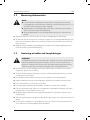
3.4 Instructions following installation
z Carry out leak detection using a UV leak detection lamp so that leaks in the Frigo cooling
system can be avoided.
z Check the efficient functioning of all cooling system components.
z Make sure that the cooling system components do not create a risk of injury for vehicle
occupants (e.g. due to sharp edges) and do not impair the function of safety features.
z Always carry out a function test aer the installation of the cooling system.
z Never change the parameter values in the control unit that are used for the basic and
backup functions of the cooling system.
z Ensure that the finishing work for the heat insulated interior in the vehicle is in perfect
condition. If this is not the case, contact the person responsible for the insulation finish-
ing work.
3.5 Checking installation conditions
A
CAUTION!
The manufacturer only assumes liability for parts included in the scope of
delivery. The validity of the warranty expires if the cooling system is installed
together with third-party parts!

8
Frigo Installation instructions
➤ Check whether the vehicle is equipped with heat insulation for the loading area.
➤ Check the requirements of the vehicle owner for the use of an electrical cooling system,
such as:
− Calculation of the required cooling capacity
− Storage temperature of the food to be transported
− Door openings per hour
Suitable measures should be adopted to prevent temperature changes that are too great
during loading and unloading, such as the installation of strip curtains on the compartment
door and other openings.
A
CAUTION!
It may not be possible for the cooling system to compensate for a high num-
ber or length of door openings, especially in distribution transport, under
some circumstances!
➤ Check the output voltage of the three phase generator (14 – 15 V).
➤ Check the efficient functioning of all electrically operated vehicle components.
➤ Check whether the idling speed is at the right value.
➤ Check the efficient functioning of the return valves and solenoid valves.
➤ Check the efficient functioning of all electrically operated vehicle components.
If faults or defects are identified, then please inform workshop management or the vehicle
owner.
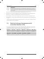
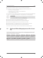
3.6 Table showing permitted tightening torques for bolts
used in Nm
If other tightening torques are not specified in this installation manual, the following table
can serve as a guide for the maximum and safe tightening torque for a specific size or sort of
fastening bolt.
M5 (0.80) M6 (1.00) M8 (1.25) M10 (1.25) M10 (1.25) M12 (1.50)
4 – 6 8 – 12 20 – 30 40 – 55 37 – 52 70 – 90
M12 (1.75) 5/8"-18UNF 3/4"-16UNF 7/8"-14UNF 1"-14UNS
60 – 85 2 – 4 3 – 5.5 4 – 6 4 – 6

9
Installation instructions Frigo
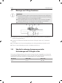
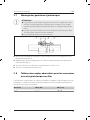
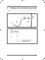
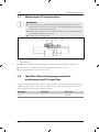
3.7 Installing O-ring fittings
A
CAUTION!
z O-ring fittings must be tightened with a smaller torque than SAE fittings
because if the tightening force is too great this could damage the seal seat
and thus cause leaks!
z Always work with two spanners when tightening or releasing a connection
in order to prevent the cables twisting!
z Reusing O-rings is not permitted!
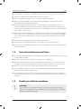
➤ Make sure that the O-ring is located on the specified fitting seat prior to commencing
installation (1).
➤ Paint refrigerant oil onto the thread and O-ring seat in the area marked with (*).
➤ Fasten the related connection thread by hand (2 and 3).
➤ Tighten the connection with two spanners.
3.8 Table showing permitted tightening torques for
connections with O-rings in Nm
If other tightening torques are not specified in this installation manual, the following table
can serve as a guide for the maximum and safe tightening torque for a specific size or sort of
connection with O-ring.
M5 (0.80) M6 (1.00) M8 (1.25)
4 – 6 8 – 12 20 – 30

10
Frigo Instructions for installation of FRIGOCLIC fittings
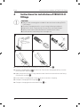
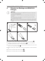
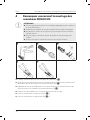
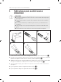
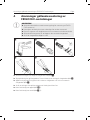
4 Instructions for installation of FRIGOCLIC
fittings
A
CAUTION!
z Only use the mounting pliers suitable for the task when installing FRIGO-
CLIC fittings!
z Check the clamping bush for correct locking following installation!
z Replace the hose clamps and the O-rings when reusing the fittings!
z Always remove the used end of the hose with the hose cutters!
z Ensure that hose ends always have a straight cut!
1 2 3
4 5
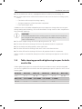
➤ Cut the hose end off with a straight cut using hose cutters (fig. 1).
➤ Slide the clamping bush onto the hose end. Position the clamping bush fully on to the
hose end until it stops (fig. 2).
➤ Apply refrigerant oil to the O-rings and the inside of the hose end and insert the fitting
into the hose end (fig. 3).
➤ Ensure that the clamping bush is fully on the hose end when clamping.
➤ Clamp the clamping bush on top (fig. 4 1).
➤ Clamp the clamping bush on the bottom (fig. 5 2).

11
Description of symbols used Frigo
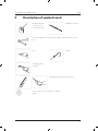
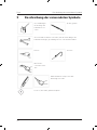
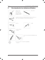
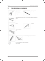
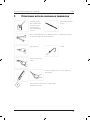
5 Description of symbols used
Apply refrigerant
oil to the screw
joints and O-rings
Straighten, smooth
Use two spanners to evenly release or fasten refrigerant line connec-
tions
Drill Solder
Cut using a ther-
mocutter
Cut material using an appropriate tool
Item / connection according to circuit dia-
gram

12
Frigo Scope of delivery
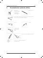
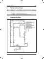
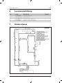
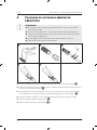
6 Scope of delivery
Item Item no. Description Quantity
1 8880900027 Low pressure switch 1
2 8881400760 Connector 1/2" 1
3 8881400725 Refrimaster plus clamp 1/2" 2
4 8881800032 Low pressure switch cable set 1
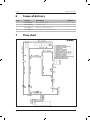
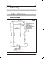
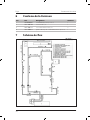
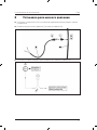
7 Flow chart

13
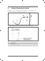
Installing low pressure switch Frigo
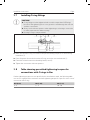
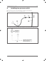
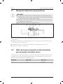
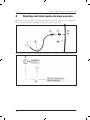
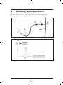
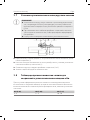
8 Installing low pressure switch
➤ Fit connector (2) into suction line between compressor and evaporator.
➤ Connect low pressure switch (1) and cable set (4).
➤ Disconnect the connection cable to the compressor, and connect to the cable set (4).

14
Frigo
Inhaltsverzeichnis
1 Erklärung der Symbole ..................................................................... 4
2 Merkblatt ........................................................................................ 4
2.1 Welches Kältemittel ist zu verwenden? .......................................................4
2.2 Welches Kompressoröl ist zu verwenden? .................................................. 4
2.3 Was ist zu tun, wenn ein Ersatzteil aus der Frigo Kühlanlage benötigt wird? .... 5
2.4 In welchen Zeitabständen sollte die Wartung einer Frigo Kühlanlage
erfolgen? ..............................................................................................5
2.5 Besteht die Möglichkeit, an einer Schulung teilzunehmen? ..........................5
3 Einbauhinweise ............................................................................... 6
3.1 Hinweise zur Montage ............................................................................ 6
3.2 Montagevorbereitung ............................................................................. 7
3.3 Umgang mit Kabeln und Schlauchleitungen ............................................... 7
3.4 Hinweise nach erfolgter Montage ............................................................. 9
3.5 Montagebedingungen prüfen ..................................................................9
3.6 Tabelle mit zulässigen Anzugsmomenten für verwendete Schrauben in Nm ....10
3.7 Montage von O-Ring-Armaturen ...............................................................11
3.8 Tabelle für zulässige Anzugsmomente für Verbindungen mit O-Ringen in Nm . 11
4 Hinweise zur Montage von FRIGOCLIC-Fittingen ................................... 12
5 Beschreibung der verwendeten Symbole ............................................ 13
6 Lieferumfang ................................................................................... 14
7 Flussdiagramm ................................................................................ 14
8 Einbau Niederdruckschalter .............................................................. 15

15
Erklärung der Symbole Frigo
1 Erklärung der Symbole
!
WARNUNG!
Sicherheitshinweis: Nichtbeachtung kann zu Tod oder schwerer Verlet-
zung führen.
!
VORSICHT!
Sicherheitshinweis: Nichtbeachtung kann zu Verletzungen führen.
A
ACHTUNG!
Nichtbeachtung kann zu Materialschäden führen und die Funktion des Gerä-
tes beeinträchtigen.
I
HINWEIS
Ergänzende Informationen zum Einbau des Produktes.
Diese Einbauhinweise sind ausgerichtet auf Monteure, die fach- und sachkundig im Bereich
der Fahrzeugklima- und Transportkältetechnik sind. Sie ersetzt nicht fehlende Kenntnis in
der Fahrzeugklimatechnik. Diese Einbauhinweise dienen nur zur besseren Orientierung
beim Einbau der Frigo Kühlanlage. Die Vollständigkeit aller Einbauschritte ist in diesem
Einbauhinweis nicht gegeben!
2 Merkblatt
Bitte vor Einbau der Kühlanlage lesen!
Bevor Sie mit dem Einbau der Frigo Kühlanlage beginnen, möchten wir Sie auf einige wich-
tige Dinge hinweisen:
2.1 Welches Kältemittel ist zu verwenden?
Die Frigo Kühlanlage wird im Temperaturbereich bis minimal +0 °C mit dem Kältemittel
R134a befüllt. Für den Temperaturbereich bis –18 °C wird die Kühlanlage mit dem Kälte-
mittel R404a befüllt.
2.2 Welches Kompressoröl ist zu verwenden?
Für Frigo Kühlanlagen mit R134a verwenden Sie bitte die bereits bekannten PAG-Öle. Für
Kühlanlagen mit R404a verwenden Sie bitte ein POE 68 Öl.

16
Frigo Merkblatt
2.3 Was ist zu tun, wenn ein Ersatzteil aus der Frigo
Kühlanlage benötigt wird?
Die Einbauanleitung beinhaltet eine Stückliste, in der alle Ersatzteile mit dazugehöriger
Artikelnummer aufgeführt sind.
Bitte bewahren Sie deshalb die Einbauanleitung gut auf.
Anhand der Artikelnummer in der Einbauanleitung platzieren Sie bitte Ihren Aurag über
Kühlanlagen-Ersatzteile direkt bei der Firma:
Dometic WAECO International GmbH – Hollefeldstr. 63 – 48282 Emsdetten –
Technischer Kundendienst – Telefon: 02572 / 879 - 191 – Telefax: 02572 / 879 - 391 –
Mail: tkd@dometic-waeco.de
2.4 In welchen Zeitabständen sollte die Wartung einer
Frigo Kühlanlage erfolgen?
Eine Wartung sollte jährlich erfolgen (z. B. dabei Austausch des Trockners, neues Kühl-
mittel, etc.).
Generell muss die Frigo Kühlanlage innerhalb der Service-Intervalle auf Funktionstüchtig-
keit überprü werden (siehe Serviceplan für Kühlanlagen).
2.5 Besteht die Möglichkeit, an einer Schulung
teilzunehmen?
Ja, wenden Sie sich diesbezüglich an die Firma Dometic WAECO International GmbH in
Emsdetten.

17
Einbauhinweise Frigo
3 Einbauhinweise
Die Einbauanleitung soll Ihnen wichtige Hinweise für die Montage geben und gleichzeitig
in Reparaturfällen als Nachschlagewerk dienen.
Sie als Einbauer der Frigo Kühlanlage tragen durch einen fachgemäßen Einbau wesentlich
zur notwendigen Betriebssicherheit und einwandfreien Leistung der Kühlanlage bei.
3.1 Hinweise zur Montage
Vor der Installation der Frigo Kühlanlage muss diese Einbauanleitung vollständig gelesen
werden.
Folgende Tipps und Hinweise müssen bei der Installation der Frigo Kühlanlage beachtet
werden:
!
WARNUNG!
Stellen Sie vor Arbeiten an elektrisch betriebenen Komponenten sicher, dass
keine Spannung mehr anliegt!
z Prüfen Sie grundsätzlich vor Montage der Kühlanlage, ob durch den Einbau der elektri-
schen Kühlanlage ggf. Fahrzeugkomponenten beschädigt oder in ihrer Funktion beein-
trächtigt werden könnten.
z Die mitgelieferten Montageteile dürfen beim Einbau nicht eigenmächtig modifiziert
werden.
z Die Lüungsöffnungen (Gitter, Verdampfer) dürfen nicht abgedeckt werden (Mindest-
abstand zu anderen Anbauteilen: 10 cm).
z Beachten Sie beim Einbau und bei der Reparatur die entsprechenden Regeln der
Technik.
z Beachten Sie bei der Montage der Kühlanlage und beim elektrischen Anschluss die
Richtlinien des Aufbauherstellers.
z Verwenden Sie die geeigneten Werkzeuge für jeden Schritt des Einbaus.
z Achten Sie vor und während des Bohrens auf den Verlauf von vorhandenen, insbeson-
dere nicht sichtbaren Kabelsträngen, Leitungen und anderen Komponenten.
!
WARNUNG!
Trennen Sie vor der Montage der Kühlanlage die Stromversorgung an der
Fahrzeugbatterie.
Bei Nichtbeachten besteht Stromschlaggefahr!

18
Frigo Einbauhinweise
!
VORSICHT!
Eine falsche Montage der Kühlanlage kann zu irreparablen Schäden am Gerät
führen und die Sicherheit des Benutzers beeinträchtigen!
Wenn die Kühlanlage nicht gemäß dieser Einbauanleitung montiert wird,
übernimmt der Hersteller keinerlei Haung – nicht für Betriebsstörungen und
nicht für die Sicherheit der Frigo Kühlanlage, insbesondere nicht für Personen-
und/oder Sachschäden!
3.2 Montagevorbereitung
!
VORSICHT!
z Lesen Sie die jeweiligen, mitgelieferten Einbauanleitungen (Fahrkühlung,
Standkühlung, Motoreinbausatz usw.) und diese Einbauhinweise sorg-
fältig.
z Schützen Sie Ihre Augen! Beim Umgang mit Kältemitteln, beim Evakuieren
und Befüllen muss unbedingt ein Augenschutz getragen werden!
z Tragen Sie Schutzkleidung! Kältemittel darf nicht in Berührung mit der Haut
geraten.
➤ Prüfen Sie die Vollständigkeit der Frigo Kühlanlage anhand der Stücklisten.
➤ Entfernen Sie Verschlusskappen von Kompressor, Verdampfer, Kondensator und Kälte-
mittelleitungen erst unmittelbar vor Einbau der betreffenden Teile, denn nur so halten
Sie das System von Feuchtigkeit und Staub frei.
➤ Geben Sie vor dem Anschließen einer Kältemittelleitung einige Tropfen Kälteöl auf den
Sitz des O-Ringes und der Überwurfmutter.
3.3 Umgang mit Kabeln und Schlauchleitungen
!
WARNUNG!
Unsachmäßige Eingriffe oder Einbauten an und in der Fahrzeugelektrik/
Fahrzeugelektronik können zu Beeinträchtigungen der einzelnen Funktio-
nen führen. Dies kann zum Ausfall von fahrzeugseitigen Komponenten oder
sicherheitsrelevanten Fahrzeugeinrichtungen und als Folge zu Unfällen mit
Personenschäden oder Schäden am Fahrzeug führen!
z Verwenden Sie Leerrohre bzw. Leitungsdurchführungen, wenn Leitungen durch scharf-
kantige Wände oder Böden geführt werden müssen.
z Achten Sie darauf, dass sämtliche, nachträglich durchgeführte Bohrungen und/oder
Durchführungen einen wasserdichten Abschluss haben.
z Führen Sie die elektrischen Leitungen so aus, dass Beschädigungen durch scharfkantige
Fahrzeugteile vermieden werden.
z Verlegen Sie keine losen oder scharf abgeknickten Kabel an elektrisch leitenden
Materialien (Metall).

19
Einbauhinweise Frigo
z Befestigen und verlegen Sie Leitungen so, dass eine Beschädigung des Kabels ausge-
schlossen ist.
z Verlegen Sie niemals die Spannungsversorgungsleitung (Batteriekabel) in räumlicher
Nähe zu Signal- oder Steuerleitungen.
z Achten Sie vor und während des Bohrens auf den Verlauf von vorhandenen, insbeson-
dere nicht sichtbaren Kabelsträngen, Leitungen und anderen Komponenten.
z Behandeln Sie nach durchgeführten Bohrungen oder Schnitten die Teile unbedingt mit
einem Korrosionsschutzmittel.
z Decken Sie Kunststoffleitungen und Bremsschläuche vor dem Bohren ab, wenn notwen-
dig bauen Sie diese aus.
z Verlegen Sie die elektrischen Leitungen so, dass sie mindestens 15 mm von drehenden
Teilen und mindestens 150 mm von stark erwärmten Teilen des Fahrzeuges entfernt
sind.
z Befestigen Sie keine Kabel, elektrische Leitungen oder Schlauchleitungen an den
Schläuchen der Bremsanlage.
z Verlegen Sie alle Schlauchleitungen und elektrische Leitungen frei von mechanischen
Belastungen.
z Befestigen Sie den Kabelsatz mit Kabelbindern und/oder mit Schlauchschellen.
z Fügen Sie die Kompaktsteckverbindungen so weit zusammen, bis die Rastpunkte fixiert
sind.
z Achten Sie darauf, dass beim Zusammenfügen der wasserdichten Steckergehäuse die
Gummidichtungen der Kabel und Steckergehäuse vorhanden sind.
z Schützen Sie Steckverbindungen, die nicht wasserdicht ausgeführt sind, in stark
spritzwassergefährdeten Bereichen (Motorraum, Unterboden) durch zusätzliches
Schutzwachsspray, Isolierband oder ähnliches. Korrosion an den Steckverbindungen
kann zum Ausfall der Kühlanlage führen.
z Stellen Sie sicher, dass nachträglich verbaute Sicherungsgehäuse außerhalb von
Spritzwasserbereichen verbaut werden. Halten Sie dabei einen Mindestabstand von
30mm zu Flüssigkeitskreisläufen ein. Zwischen den Sicherungsgehäusen und brenn-
baren Flüssigkeiten (Benzinfilter, Tank usw.) muss ein Abstand von 300 mm eingehalten
werden.
z Verbauen Sie die Sicherungsgehäuse so nah wie möglich an der Batterie.
z Schließen Sie an belegten Sicherungen keine zusätzlichen Verbraucher an.
z Schließen Sie an vorhandenen Kabelleitungen keine zusätzlichen Kabel (z. B. Schneid-
klemmen) an.

20
Frigo Einbauhinweise
3.4 Hinweise nach erfolgter Montage
z Führen Sie eine Lecksuche mit einer UV-Lecksuchlampe durch, so dass Undichtigkeiten
der Frigo Kühlanlage vermieden werden.
z Überprüfen Sie die Funktionsfähigkeit aller Komponenten der Kühlanlage.
z Stellen Sie sicher, dass durch die Komponenten der Kühlanlage keine Verletzungs gefahr
für die Fahrzeuginsassen (z. B. durch scharfe Kanten) entsteht und fahrzeugseitige
Sicherheitseinrichtungen nicht in ihrer Funktion beeinträchtigt werden.
z Führen Sie grundsätzlich nach der erfolgten Endmontage der Kühlanlage eine
Funktions prüfung durch.
z Verändern Sie niemals Parameterwerte im Bedienteil, die zu Grund- und Sicherungs-
funktionen der Kühlanlage dienen.
z Stellen Sie sicher, dass sich der im Fahrzeug befindliche Ausbau des wärmegedämmten
Innenraums in einem einwandfreien Zustand befindet. Trifft dieses nicht zu, wenden Sie
sich an den Ausbauer der Isolierung.
3.5 Montagebedingungen prüfen
A
ACHTUNG!
Der Hersteller übernimmt ausschließlich Haung für im Lieferumfang enthal-
tene Teile. Beim Einbau der Kühlanlage zusammen mit produktfremden Teilen
entfallen die Gewährleistungsansprüche!
➤ Prüfen Sie, ob das Fahrzeug mit einer wärmegedämmten Isolierung für den Laderaum
ausgestattet ist.
➤ Prüfen Sie die Anforderungen des Fahrzeughalters für den Einsatz einer elektrischen
Kühlanlage wie:
− Berechnung des geforderten Kälteleistungsbedarfs
− Lagertemperatur der zu transportierenden Lebensmittel
− Türöffnungen pro Stunde
Zur Vermeidung von zu großen Temperaturänderungen während des Be- und Entladens
sind geeignete Maßnahmen zu treffen, wie z. B. der Einbau von Streifenvorhängen an den
Laderaumtüren und anderen Öffnungen.
La page est en cours de chargement...
La page est en cours de chargement...
La page est en cours de chargement...
La page est en cours de chargement...
La page est en cours de chargement...
La page est en cours de chargement...
La page est en cours de chargement...
La page est en cours de chargement...
La page est en cours de chargement...
La page est en cours de chargement...
La page est en cours de chargement...
La page est en cours de chargement...
La page est en cours de chargement...
La page est en cours de chargement...
La page est en cours de chargement...
La page est en cours de chargement...
La page est en cours de chargement...
La page est en cours de chargement...
La page est en cours de chargement...
La page est en cours de chargement...
La page est en cours de chargement...
La page est en cours de chargement...
La page est en cours de chargement...
La page est en cours de chargement...
La page est en cours de chargement...
La page est en cours de chargement...
La page est en cours de chargement...
La page est en cours de chargement...
La page est en cours de chargement...
La page est en cours de chargement...
La page est en cours de chargement...
La page est en cours de chargement...
La page est en cours de chargement...
La page est en cours de chargement...
La page est en cours de chargement...
La page est en cours de chargement...
La page est en cours de chargement...
La page est en cours de chargement...
La page est en cours de chargement...
La page est en cours de chargement...
La page est en cours de chargement...
La page est en cours de chargement...
La page est en cours de chargement...
La page est en cours de chargement...
La page est en cours de chargement...
La page est en cours de chargement...
La page est en cours de chargement...
La page est en cours de chargement...
La page est en cours de chargement...
La page est en cours de chargement...
La page est en cours de chargement...
La page est en cours de chargement...
La page est en cours de chargement...
La page est en cours de chargement...
La page est en cours de chargement...
La page est en cours de chargement...
La page est en cours de chargement...
La page est en cours de chargement...
La page est en cours de chargement...
La page est en cours de chargement...
-
 1
1
-
 2
2
-
 3
3
-
 4
4
-
 5
5
-
 6
6
-
 7
7
-
 8
8
-
 9
9
-
 10
10
-
 11
11
-
 12
12
-
 13
13
-
 14
14
-
 15
15
-
 16
16
-
 17
17
-
 18
18
-
 19
19
-
 20
20
-
 21
21
-
 22
22
-
 23
23
-
 24
24
-
 25
25
-
 26
26
-
 27
27
-
 28
28
-
 29
29
-
 30
30
-
 31
31
-
 32
32
-
 33
33
-
 34
34
-
 35
35
-
 36
36
-
 37
37
-
 38
38
-
 39
39
-
 40
40
-
 41
41
-
 42
42
-
 43
43
-
 44
44
-
 45
45
-
 46
46
-
 47
47
-
 48
48
-
 49
49
-
 50
50
-
 51
51
-
 52
52
-
 53
53
-
 54
54
-
 55
55
-
 56
56
-
 57
57
-
 58
58
-
 59
59
-
 60
60
-
 61
61
-
 62
62
-
 63
63
-
 64
64
-
 65
65
-
 66
66
-
 67
67
-
 68
68
-
 69
69
-
 70
70
-
 71
71
-
 72
72
-
 73
73
-
 74
74
-
 75
75
-
 76
76
-
 77
77
-
 78
78
-
 79
79
-
 80
80


Dometic Frigo 8883000402 Guide d'installation
- Taper
- Guide d'installation
- Ce manuel convient également à
dans d''autres langues
Documents connexes
-
Dometic Frigo - Defrosting for water drain Guide d'installation
-
-
-
-
-
-
-
-
-
Waeco CB-1200-AC, CB-1200-AC/DC Guide d'installation