
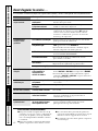
Cool Only: AJCH 08, 10 ACB
AJCH 10, 12 DCB
AJCQ 08, 10 ACB
AJCQ 10, 12 DCB
AJCS 06 LCB
AJCS 08, 10 ACB
AJCS 09, 10, 12 DCB
Heat/Cool: AJEH 12 DCB
AJES 06 LSB
AJES 08 ASB
AJES 09, 10, 12 DCB
AJES 10 DSB
Heat Pump: AJHS 08 ASB
AJHS 08, 10 DCB
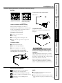
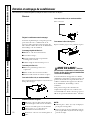
Write the model and serial numbers here:
Model # __________________________
Serial #
____________________________
Find these numbers on a label on the front
of the base pan behind the front grille.
Air Conditioners
www.GEAppliances.com
Room

2
Consumer Support Troubleshooting Tips Installation Instructions Care and Cleaning Operating Instructions Safety Instructions
IMPORTANT SAFETY INFORMATION.
READ ALL INSTRUCTIONS BEFORE USING.
WARNING!
For your safety, the information in this manual must be followed to minimize the risk of fire, electric
shock or personal injury.
■ Use this appliance only for its intended
purpose as described in this Owner’s
Manual.
■ This air conditioner must be properly
installed in accordance with the
Installation Instructions before it is used.
■ Never unplug your air conditioner by
pulling on the power cord. Always grip
plug firmly and pull straight out from the
receptacle.
■ Repair or replace immediately all electric
service cords that have become frayed or
otherwise damaged. Do not use a cord
that shows cracks or abrasion damage
along its length or at either the plug or
connector end.
■ Turn the mode control OFF and unplug
your air conditioner before making any
repairs or cleaning.
NOTE: We strongly recommend that any
servicing be performed by a qualified
individual.
■ For your safety…do not store or use
combustible materials, gasoline or other
flammable vapors or liquids in the vicinity
of this or any other appliance.
■ All air conditioners contain refrigerants,
which under federal law must be removed
prior to product disposal. If you are getting
rid of an old product with refrigerants,
check with the company handling disposal
about what to do.
SAFETY PRECAUTIONS
Do not, under any circumstances, cut or remove
the third (ground) prong from the power cord.
For personal safety, this appliance must be
properly grounded.
The power cord of this appliance is equipped
with a 3-prong (grounding) plug which
mates with a standard 3-prong (grounding)
wall outlet to minimize the possibility of
electric shock hazard from this appliance.
Have the wall outlet and circuit checked
by a qualified electrician to make sure the
outlet is properly grounded.
Where a 2-prong wall outlet is encountered,
it is your personal responsibility and
obligation to have it replaced with a properly
grounded 3-prong wall outlet.
The air conditioner should always be plugged
into its own individual electrical outlet which
has a voltage rating that matches the rating
plate.
This provides the best performance and also
prevents overloading house wiring circuits
which could cause a fire hazard from
overheated wires.
See the Installation Instructions, Electrical
Requirements section for specific electrical
connection requirements.
HOW TO CONNECT ELECTRICITY

Safety Instructions Operating Instructions Care and Cleaning Installation Instructions Troubleshooting Tips Consumer Support
3
www.GEAppliances.com
WARNING!
Because of potential safety hazards under
certain conditions, we strongly recommend
against the use of an extension cord.
However, if you must use an extension cord,
it is absolutely necessary that it be a UL-listed,
14 gauge, 3-wire grounding type appliance
extension cord having a grounding type plug
and outlet and that the electrical rating of
the cord be 15 amperes (minimum) and
125 volts.
CAUTION:
DO NOT use an extension cord with any of the
230/208 volt models.
USE OF EXTENSION CORDS—115-Volt models only
Because of potential safety hazards under
certain conditions, we strongly recommend
against the use of an adapter plug.
However, if you must use an adapter, where
local codes permit, a temporary connection
may be made to a properly grounded
2-prong wall outlet by use of a UL-listed
adapter available at most local hardware
stores.
The larger slot in the adapter must be
aligned with the larger slot in the wall
outlet to provide proper polarity in the
connection of the power cord.
When disconnecting the power cord from
the adapter, always hold the adapter in place
with one hand while pulling the power cord
plug with the other hand. If this is not done,
the adapter ground terminal is very likely to
break with repeated use.
If the adapter ground terminal breaks,
DO NOT USE the air conditioner until a
proper ground has been established.
Attaching the adapter ground terminal to a wall
outlet cover screw does not ground the appliance
unless the cover screw is metal, not insulated, and
the wall outlet is grounded through the house wiring.
You should have the circuit checked by a qualified
electrician to make sure the outlet is properly
grounded.
USE OF ADAPTER PLUGS—115-Volt models only
READ AND FOLLOW THIS SAFETY INFORMATION CAREFULLY.
SAVE THESE INSTRUCTIONS


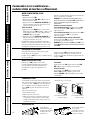
Vent Control
The vent control is located behind the front grille on
the right side of the air discharge area. When set at
CLOSE, only the air inside the room will be circulated
and conditioned. When set at OPEN, some inside air is
exhausted outside.
To open or close the vent:
1. Remove the front grille.
2. Remove the vent card screw.
3. Remove vent card, turn it over and replace it by
locating rear hole in card over locating pin inside air
discharge and reattaching screw at front.
Horizontal louvers
on the front grille let
you control the air
direction up and
down.
Remove the front
grille to adjust the
vertical louvers
side-to-side to
direct the air
left or right.
Safety Instructions Operating Instructions Care and Cleaning Installation Instructions Troubleshooting Tips Consumer Support
5
Air Direction
Locating hole
www.GEAppliances.com
COOL MODE
Remote Control
1. Press COOL pad.
2. Press LOW, MED or HI pads to set desired fan speed.
3. Press the INCREASE ▲ / DECREASE ▼ pads to set the
desired temperature 60°F to 85°F in 1°F increments.
Control Panel
1. Press the MODE pad until the COOL indicator light is
lit and the LOW, MED or HI indicator light is lit for
the desired fan speed.
2. Press the INCREASE ▲ / DECREASE ▼ pads to set the
desired temperature 60°F to 85°F in 1°F increments.
A thermostat is used to maintain the room
temperature. The compressor will cycle on and off
to keep the room at the set level of comfort. Set the
thermostat at a lower number and the indoor air will
become cooler. Set the thermostat at a higher number
and the indoor air will become warmer.
NOTE: If the air conditioner is off and is then turned on
while set to COOL, it will take approximately 3 minutes for
the compressor to start and cooling to begin.
Cooling Descriptions
For Normal Cooling—Select the COOL mode and
HIGH or MED fan with a middle set temperature.
For Maximum Cooling—Select the COOL mode
and HIGH fan with a lower set temperature.
For Quieter & Nighttime Cooling—Select the COOL mode
and LOW fan with a middle set temperature.
NOTE: If you switch from a COOL setting to OFF or to
a fan setting, wait at least 3 minutes before switching back
to a COOL setting.
FAN MODE
Use the FAN mode to provide air circulation and
filtering without cooling. Since fan only settings do not
provide cooling, a temperature setting will not be
displayed.
Remote Control
Press FAN pad. Press LOW, MED or HI pads to set
desired fan speed.
Control Panel
Press the MODE pad until the FAN indicator light is lit
and the LOW, MED or HI indicator light is lit for the
desired fan speed.
Fan Switch
The fan switch is located behind the front grille on the
control box.
When set at CYCLE (down) the fan cycles on and off.
When set at CONT (continuous, up) the fan runs all the
time providing a more balanced temperature. The unit
is shipped in the CONT setting.
Screw hole
OPEN position
(Mesh end toward back)
CLOSE position
(Mesh end toward front)
Locating hole
Screw hole
The unit leaves the factory set at the CLOSE position.

Consumer Support Troubleshooting Tips Installation Instructions Care and Cleaning Operating Instructions Safety Instructions
6
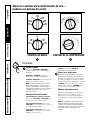
Controls
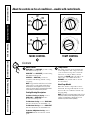
Mode Control
HIGH COOL and LOW COOL provide cooling
with different fan speeds.
HIGH HEAT and LOW HEAT provide heating
with different fan speeds.
LOW FAN or HIGH FAN provides air
circulation and filtering without cooling
or heating.
NOTE: If you move the switch from a cool or heat
setting to OFF or to a fan setting, wait at least 3
minutes before switching back to a cool or heat
setting. A 3-minute delay is automatically provided
on the Heat/Cool and Heat Pump models.
Cooling/Heating Descriptions
For Normal Cooling or Heating—Select
HIGH COOL or HIGH HEAT with the
thermostat at mid point.
For Maximum Cooling—Select HIGH COOL
with the thermostat at maximum cool.
For Maximum Heating—Select HIGH HEAT
with the thermostat at maximum heat.
For Quieter & Nighttime Cooling—Select
LOW COOL with the thermostat at mid
point.
Temp Control
The temp control is used to maintain the
room temperature. The compressor will
cycle on and off to keep the room at the
same level of comfort. When you turn
the knob to COOLER (blue) the indoor air
will become cooler. Turn the knob to
WARMER (red) and the indoor air will
become warmer.
Heat Pump Models
When the outdoor temperature is lower
than 25°F., heat is provided by the electric
heater in the air conditioner instead of by
the heat pump.
NOTE: The electric resistance heater in the 115-volt
heat pump model operates during defrost when the
outdoor coil temperature is below 36°F. It is not
intended to provide full heat capability.
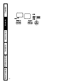
MODE CONTROL TEMP CONTROL
OFF
LOW
FAN
HIGH
FAN
HIGH
HEAT
HIGH
COOL
LOW
COOL
LOW
HEAT
W
A
R
M
E
R
C
O
O
L
E
R
OFF
LOW
FAN
HIGH
FAN
HIGH
COOL
LOW
COOL
C
O
O
L
E
R
About the controls on the air conditioner—models with control knobs.

Horizontal louvers
on the front grille
let you control the
air direction up
and down.
Remove the front
grille to adjust the
vertical louvers
side-to-side to
direct the air left
or right.
7
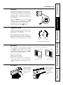
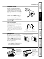
Temperature Limiting
Limiting the maximum and minimum settings
prevents users from turning the control to the
extreme heat or cool positions.
The normal range of the temp control is
approximately 60°F to 85°F. The control range
may be narrowed by the use of the temperature
limiting screws located behind the control panel.
Each position equals approximately 3°F.
Air Direction
Fan Switch
On Heat/Cool models, the fan switch lever is
located in a hole through the control panel. To
reach it, you need to remove the front grille. Use
a small screwdriver to change the setting. Cool
only models have a rocker switch on the front of
the control box.
When set at CYCLE (down) the fan cycles on and
off when cooling or heating. When set at CONT
(continuous, up) the fan runs all the time,
providing a more balanced temperature.
The unit is shipped in the CONT setting.
www.GEAppliances.com
Limits
heat
temp
Limits
cool
temp
Safety Instructions Operating Instructions Care and Cleaning Installation Instructions Troubleshooting Tips Consumer Support
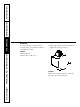
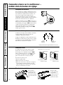
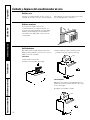
Vent Control
The vent control is located behind the front grille
on the right side of the air discharge area. When
set at CLOSE, only the air inside the room will be
circulated and conditioned. When set at OPEN,
some inside air is exhausted outside.
To open or close the vent:
1. Remove the front grille.
2. Remove the vent card screw.
3. Remove vent card, turn it over and replace it
by locating rear hole in card over locating pin
inside air discharge and reattaching screw at
front.
Locating hole
Screw hole
OPEN position
(Mesh end toward back)
CLOSE position
(Mesh end toward front)
Locating hole
Screw hole
The unit leaves the factory set at the CLOSE position.

Consumer Support Troubleshooting Tips Installation Instructions Care and Cleaning Operating Instructions Safety Instructions
8
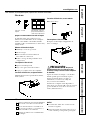
The front grille can be removed for more
thorough cleaning or to make the model and
serial numbers accessible.
To remove:
1. Pull the filter out.
2. Remove the two grille screws.
3. Pull the grille out from the bottom and lift up
from the tabs on the top of the case.
To replace:
Hook the tabs on the front grille even with the
tabs on the case and snap into place.
Replace the screws and filter.
Front Grille

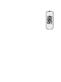
How to Insert the Batteries
Remove the battery cover by sliding it
according to the arrow direction.
Insert new batteries making sure that the
(+) and (–) of battery are installed correctly.
Reattach the cover by sliding it back
into position.
NOTES:
■ Use 2 AAA (1.5 volt) batteries. Do not use
rechargeable batteries.
■ Remove the batteries from the remote control
if the system is not going to be used for a long
time.
3
2
1
9
www.GEAppliances.com
Safety Instructions Operating Instructions Care and Cleaning Installation Instructions Troubleshooting Tips Consumer Support
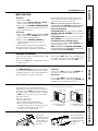
To maintain optimum performance, clean the filter at least every 30 days.
Air Filter
Turn the air conditioner off before cleaning.
The most important thing you can do to
maintain the air conditioner is to clean the filter
at least every 30 days. A clogged filter reduces
cooling, heating and air flow.
Keeping the air filter clean will:
■ Decrease cost of operation.
■ Save energy.
■ Prevent clogged heat exchanger coils.
■ Reduce the risk of premature component
failure.
To clean the air filters:
■ Vacuum off the heavy soil.
■ Run water through the filters.
■ Dry thoroughly before replacing.
To remove the air filter, on some models:
Carefully pull the tab forward, up and out.
To remove the air filter, on other models:
Pull it down.
To replace the air filter:
Replace the clean filter by pushing it back
into place.
CAUTION: Do not operate the air
conditioner without the filter in place. If a filter
becomes torn or damaged it should be replaced
immediately.
Operating without the filter in place or with a
damaged filter will allow dirt and dust to reach
the indoor coil and reduce the cooling, heating,
airflow and efficiency of the unit.
Replacement filters are available from your
salesperson, GE dealer, GE Service and Parts
Center or authorized Customer Care
®
servicers.
Dirty filter—Needs cleaning Clogged filter—Greatly
reduces cooling, heating
and airflow.
FRONT
FRONT

BEFORE YOU BEGIN
Read these instructions completely and carefully.
•
IMPORTANT — Save these instructions
for local inspector’s use.
•
IMPORTANT — Observe all governing
codes and ordinances.
• Note to Installer – Be sure to leave these
instructions with the Consumer.
• Note to Consumer – Keep these instructions for
future reference.
• Skill level – Installation of this appliance
requires basic mechanical skills.
• Completion time – Approximately 1 hour
• We recommend that two people install this
product.
• Proper installation is the responsibility of the
installer.
• Product failure due to improper installation is
not covered under the Warranty.
Questions? Call 800.GE.CARES (800.432.2737) or Visit our Website at: www.GEAppliances.com
Installation
Air Conditioner
Instructions
Some models require a 115/120-volt a.c.,
60 Hz grounded outlet protected with a
15-amp time delay fuse or circuit breaker.
The 3-prong grounding plug minimizes the possibility
of electric shock hazard. If the wall outlet you plan to
use is only a 2-prong outlet, it is your responsibility to
have it replaced with a properly grounded 3-prong
wall outlet.
Some models require 230/208-volt a.c.,
protected with a time delay fuse or circuit
breaker. These models should be installed on
their own single branch circuit for best
performance and to prevent overloading
house or apartment wiring circuits, which
could cause a possible fire hazard from
overheating wires.
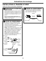
ELECTRICAL REQUIREMENTS
CAUTION:
Do not, under any circumstances, cut or remove
the third (ground) prong from the power cord.
Do not change the plug on the power cord
of this air conditioner.
Aluminum house wiring may present special
problems—consult a qualified electrician.
IMPORTANT!
GE strongly recommends the removal of the old wall
case and the installation of a new GE Wall Case. If
you decide to keep the existing wall case, you may
need a kit to ensure proper performance. If you DO
NOT use a kit, you run the risk of poor performance
or product failure. This is not covered under the
terms of the GE warranty.
J-MODEL QUALIFYING QUESTIONS
J-model air conditioners may fit in existing wall
cases. However, they often need a kit to properly
adapt the case to the GE air conditioner. Answer
these questions and see the chart on the next page
for the proper kit.
What brand air conditioner will you be
replacing?
What are the dimensions of the wall case
currently in use?
What is the model number of the chassis
currently in use? What is the model (or Type)
number of the wall case currently in use?
Frequently, the J-model adapter kit will apply to
another brand model “series” or specific vintage.
In these cases, you need the chassis model
number and/or the wall case or “type” number
to confirm the use of the correct adapter kit.
What type of outdoor grille is used with the
current wall case?
There may be an architectural grille attached to
a wall case to enhance the exterior appearance
of the building. Custom grilles may be used with
J-model wall cases provided a J-model adapter
kit is also used to ensure proper airflow.
A
C
D
B
10

11
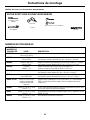
GE KIT NUMBERS
Read these instructions completely and carefully.
Installation Instructions
USE GE
KIT NUMBER: FOR: DESCRIPTION:
RAK56A100 GE RAB13, 14 & 15 Fits all GE wall cases 26″W x 18″H x 24″D
(ACLB & RCL Chassis)
RAK1072 Hotpoint ACXB10 & 11 Adapts an older Hotpoint wall case to a “J”
(ACTB Chassis) model chassis. Fits Hotpoint wall cases
25
3
⁄4″W x 16
7
⁄8″H x 18
5
⁄8″D
RAK1082 Whirlpool Type 23W Adapts Whirlpool wall case to a “J”
Wall Case model chassis. Fits Whirlpool wall
cases 25
7
⁄8″W x 16
1
⁄2″H x 23
1
⁄8″D
RAK1102 GE RAB30 Adapts GE wall case to a “J” model chassis.
(“F” models) Fits the RAB 30 wall case 26″W x 18″H x 24″D
RAK123A64 Fedders Wall Case “A” Adapts Fedders wall case to a “J” model chassis.
Fits Fedders wall cases 27″W x 16
3
⁄4″H x 16
3
⁄4″D
RAK126 Westinghouse Wall Case Adapts Westinghouse wall case to a “J”
(Type 2626D73H01) model chassis. Fits Westinghouse wall
cases 25
7
⁄8″W x 15
7
⁄16″H x 16″D
RAB46, 47 & 48 Use these kits for all Standard wall case for “J” model chassis.
other brands not listed. RAG13 stamped aluminum exterior grille
included. Remove the existing case
and replace.
RAK690 RAB36, 37, 38, 46, 47 or 48 If you attach a custom architectural outdoor
(J-Chassis) grille, use this kit to ensure proper airflow.
RAG13 RAB36, 37, 38, 46, 47 or 48 Standard aluminum exterior grille (included with RAB46, 47, and 48 wall
(J-Chassis) cases)
RAG14E RAB36, 37, 38, 46, 47 or 48 Architectural louvered exterior grille
(J-Chassis)
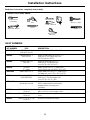
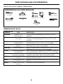
TOOLS YOU MAY NEED
Adjustable Wrench
Level
Phillips head
screwdriver
Hand or Saber Saw
Drill
Pencil
Ruler or Tape
Measure
Scissors or knife

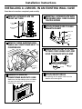
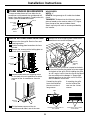
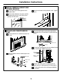
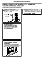
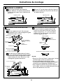
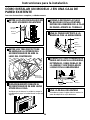
REMOVE THREE SHIPPING PADS
INSIDE AIR CONDITIONER NEXT TO
COMPRESSOR
Installation Instructions
REMOVE LOCKING PLATE ON
FRONT LEFT SIDE
1
REINSTALL LOCKING PLATE WITH
TAB BEHIND WALL CASE FLANGE.
TIGHTEN SCREW
Locking
plate
Remove
screw
INSTALLING A J-MODEL IN AN EXISTING WALL CASE
Read these instructions completely and carefully.
Remove
shipping
pads
CAREFULLY SLIDE AIR
CONDITIONER BACK INTO CASE
Make sure that the tubing on the unit does
not touch the wall case and that the case
installation is secure.
2
3
12
WHEN WALL OUTLET IS TO LEFT,
EXTEND CORD UNDER UNIT AND
HOLD IT IN PLACE WITH CLAMP
Power
cord
Clamp
ATTACH FRONT GRILLE
An opening for the power cord is on the
bottom of the front grille.
6
ATTACH POWER CORD TO BASE
PAN WITH CLAMP
Clamp
Power
cord
Base pan
4
5
7

13
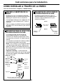
Installation Instructions
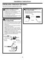
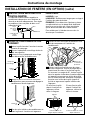
PREPARE OPENING IN WALL
Make certain a wall receptacle is
available close to the hole location or make
arrangements to install a receptacle.
The cord length for the 115-volt models is 72″
to the right and 47″ to the left.
For the 230/208-volt models the cord length is
65″ to the right and 39″ to the left.
1
INSTALLING THROUGH THE WALL
Read these instructions completely and carefully.
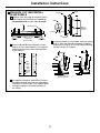
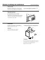
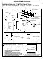
SUPPORT REQUIREMENTS FOR
AIR CONDITIONER
The air conditioner wall case may be installed
with 1/4″ min. extension out from the inside
wall or with 1/4″ min. extension out from the
outside wall.
The finished sides of the opening should be
structural wall members.
Lintel – Use a lintel in brick veneer and brick
and block types of wall to support the bricks
or blocks above the opening. Do not allow the
wall case to be used in lieu of a lintel.
Flashing – Install flashing (drip rail) as shown
to prevent water from dripping inside the wall
and down the outside of the building.
2
Trim
molding
(if desired)
Plaster
line
Caulking
(above &
below
the
flashing)
Flashing
(drip rail)
1/4″ min. extension
inside the wall from
the trim molding
Room side
Brick veneer
Lintel angle
(if required)
Caulking
(on all 4
sides on the
outside of
the case)
SUPPORT REQUIREMENTS FOR
AIR CONDITIONER
Mortar between the case and the brick all
around the case may be undercut at about 45°
for improved caulking.
3
Caulking
Top of case
Inside
Outside
Undercut
mortar

Installation Instructions
14
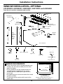
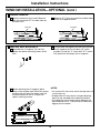
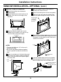
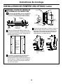
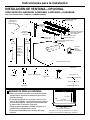
WINDOW INSTALLATION—OPTIONAL
FOR MODELS AJES06LSB, AJES08ASB, AJES10DSB and AJHS08ASB
Read these instructions completely and carefully.
Air conditioner
Type C (painted) (6)
Type D (2)
Type E (4)
Large washer (2)
Adjusting bolt (2)
Lock nut (2)
Spacer (2)
Support bracket hardware
Type A (9)
Type B (2)
Sill support
bracket (2)
2 angles
(left and
right hand)
Case side
gasket (2)
Spring
clip (4)
Window
locking
bracket
Vinyl window
gasket
Bottom window gasket
Filler
Panels
Cut panels
and
discard
center
piece
Case top gasket
Foam top
window gasket
B
Right
side
A
Left side
(holes are on the left)
(holes are on the right)
WINDOW REQUIREMENTS
• These instructions are for a standard double-hung
window. You will need to modify them for other
types of windows.
• The air conditioner can be installed without the
accordion panels if needed to fit in a narrow
window. See the window opening dimensions
to the right.
• All supporting parts must be secured to firm wood,
masonry or metal.
• The electrical outlet must be within reach of the
power cord.
1
Window opening dimensions are for a
standard double-hung window.
17″ min.
31″ to 43″
(With filler panels)
26
1
⁄4″ min.
(Without filler panels)

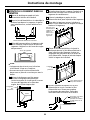
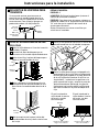
REMOVE AIR CONDITIONER FROM CASE
Remove the front grille. See the Care and
Cleaning section.
Find the locking plate located on the front
left side.
Remove the screw and the locking plate to
unlock the air conditioner.
Remove and discard the shipping screw
on the back of the air conditioner to allow
removal of the air conditioner from the
case.
Pull the bottom corners of the air
conditioner and slide it out of the case.
Remove the three shipping pads inside the air
conditioner next to the compressor.
Remove the rear grille that is taped to the back
of the case. Remove the packet of screws taped
to the back of the grille. While holding the grille
at a 45° angle, insert it into the clips at the top of
the case and push the bottom in. Keep slight
upward pressure on the grille until it fits flush
with the bottom of the case.
15
STORM WINDOW REQUIREMENTS
A storm window frame will not allow the air
conditioner to tilt towards the outside and will
keep it from draining properly. To adjust for this,
attach a piece of wood to the stool.
WOOD PIECES:
WIDTH: 2″
LENGTH: Long enough to fit inside the window
frame.
THICKNESS: To determine the thickness, place a
piece of wood on the stool to make it 1/2″ higher
than the top of the storm window frame.
Attach securely with nails or screws provided by
the installer.
2
1/2″ higher
than
frame
Storm
window
frame
Wood
Stool
Sill
3
A
B
C
Locking
plate
Remove
screw
D
Remove
screw
E
F
If attaching the grille
from the outside of
the case use the 2
long screws.
If attaching the grille
on the inside of the
case use the 2 short
screws.
G
Clips
Insert the 2 long screws on
the outside
Insert the 2 short screws
on the inside
Installation Instructions
Remove
shipping
pads

Installation Instructions
16
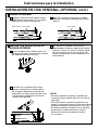
INSTALL SILL SUPPORTS
Assemble the sill supports. Do not fully
tighten the spacer mounting screws at this
time.
Before attaching the sill supports, place
them on the window stool. Select the spacer
position that will place the spacer near the
outermost point on the sill. Tighten the
spacer mounting screws.
Turn the bolts and tighten the lock nuts to make
the sill supports level or tilt down 1/8″ to the
outside. Line up the “V” notch with 12
3
⁄8″ marks.
Drill pilot holes and attach the sill supports.
NOTES:
• On narrow sills, there may not be enough room to
use the lock nut.
• A deep offset sill may require a longer adjusting
bolt than the standard hex head bolt provided.
• On wood sills use the large washer between the
bolt head and the sill. This prevents the bolt from
digging into the wood.
PREPARE WINDOW
Mark the centerline of the stool. Measure
from the centerline 13
3
⁄8″ on both sides for
the panel cuts.
Measure 12
3
⁄8″ from the centerline on both sides
for the sill support brackets.
4
A
B
WINDOW INSTALLATION—OPTIONAL (cont.)
Stool
Sill
13
3
⁄8″
Centerline
12
3
⁄8″
Centerline
5
A
B
C

Installation Instructions
17
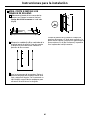
MEASURE, CUT AND INSTALL
FILLER PANELS
Measure from the edge of the panel marks
(see Prepare the Window) to the inside of
the window track on each side. (A and B)
Mark the A and B measurements on each
side of the filler panel board. Cut the panels
and discard the center piece. Note position
of the notches.
Put together the panel assemblies. Remove
the paper backing from the case side gasket
and attach it to the angle. Push a pencil point
through the gaskets to locate the holes in
the angles.
Install the panels in the window. Place the spring
clips 3″ from the top and the bottom. Squeeze
and push the clips to fit in the window track and
the tab into the sill support.
6
A
B
C
D
Sill
A
Window track
Width of the air
conditioner
(panel marks)
Left side
B
Right side
13
3
⁄8″ 13
3
⁄8″
Filler
Panels
Cut
panels
and
discard
center
piece
B
Right
side
A
Left
side
(holes are on the left)
(holes are on the right)
Gasket
Gasket
Angle
Panel
Tab
Type C
(painted
screws)
Angle
Hook the tab into
the sill support
3″

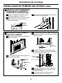
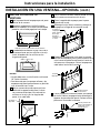
INSTALL CASE IN WINDOW
Peel off the backing from the bottom
window gasket.
Place the gasket on the stool and over the
brackets, even with the rear edge, sticky
side down.
Carefully slide the empty case into the
window until the holes in the case line up
with the holes in the panel angles.
NOTES:
• The case should have a 1/8″ minimum tilt
toward the outside.
• Be sure the seal gasket and panel gaskets
remain in position and do not roll with the
case.
Lower the window so it fits behind the panel
tabs. Insert the 4 type A screws through the
holes in the case and into the panel angles,
2 on each side.
With the window closed, mark where the
window sash meets the case.
Peel off the backing from the case top gasket.
Hold on to the case, open the window, and
place the gasket along the mark on the case.
Place the vinyl window gasket over the case top
gasket. Insert the panel tabs through the slits in
the gasket. Cut the gasket on each side to the
width of the window.
Close the window tightly on the vinyl gasket.
Bend the gasket forward to expose the panel
tabs. Drill pilot holes into the window sash.
Installation Instructions
18
WINDOW INSTALLATION—OPTIONAL (cont.)
7
A
B
C
D
E
F
G
H
I
Bottom window gasket
Case holes
Panel
tabs
Case
screws
Put the gasket
on top of the
case where
the window
will close.
Panel
tab
Vinyl window
gasket
Attach the panel tab
to the window on
each side with a type
D screw.

Installation Instructions
19
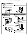
REPLACE AIR CONDITIONER IN
CASE
Carefully slide the air conditioner back into
the case.
Attach the power cord to the base pan with
the clamp.
When the wall outlet is to the left, extend the
cord under the unit and hold it in place with the
clamp.
Reinstall the locking plate with the tab behind the
wall case flange. Tighten the screw.
Reattach the front grille. An opening for the
power cord is on the bottom of the front grille.
Fill holes and cracks with caulking provided by
the installer
.
INSTALL WINDOW GASKET AND
LOCKING BRACKET
Cut the foam top window gasket to the
window width.
Stuff the foam between the glass and the
window to prevent air and insects from
getting into the room.
Attach the window locking bracket with 1 type E
screw.
8
A
B
9
A
B
C
C
D
E
F
Clamp
Power cord
Base pan
Power cord
Clamp
Locking
plate
Tighten
screw

Consumer Support Troubleshooting Tips Installation Instructions Care and Cleaning Operating Instructions Safety Instructions
20
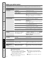
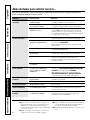
Before you call for service…
Troubleshooting Tips: Save time and money! Review the chart below first and you may not need to call for service.
Normal Operating Sounds
■ You may hear a pinging noise caused by
water being picked up and thrown against the
condenser on rainy days or when the humidity
is high. This design feature helps remove
moisture and improve efficiency.
■ You may hear the thermostat click when the
compressor cycles on and off.
■ Water will collect in the base pan during
high humidity or on rainy days. The water
may overflow and drip from the outdoor side
of the unit.
■ The fan may run even when the compressor
does not.
Problem Possible Causes What To Do
Air conditioner The air conditioner • Make sure the air conditioner plug is pushed
does not start is unplugged. completely into the outlet.
The fuse is blown/circuit • Check the house fuse/circuit breaker box and
breaker is tripped. replace the fuse or reset the breaker.
Power failure. • If power failure occurs, turn the air conditioner
OFF. When power is restored, wait 3 minutes to
restart the air conditioner to prevent tripping of
the compressor overload.
Air conditioner does Airflow is restricted. • Make sure there are no curtains, blinds or furniture
not cool as it should blocking the front of the air conditioner.
The temp control may • On models with touch pads: In COOL mode, press the
not be set correctly. DECREASE ▼ pad.
• On models with control knobs, turn the temperature
knob to a higher number.
The air filter is dirty. • Clean the filter at least every 30 days.
See the Operating Instructions section.
The room may have been hot. • When the air conditioner is first turned on, you need
to allow time for the room to cool down.
Cold air is escaping. • Check for open furnace registers and cold air returns.
• Set the air conditioner’s vent to the closed position.
Cooling coils have iced up. • See “Air conditioner freezing up” below.
Air conditioner Ice blocks the airflow • On models with control knobs, set the mode control
freezing up and stops the air conditioner at HIGH FAN or HIGH COOL with the temp at WARMER.
from cooling the room.
• On models with touch pads, set the controls at
HIGH FAN or HIGH COOL and set the thermostat to
a higher temperature.
The remote control is The batteries are inserted • Check the position of the batteries. They should be
not working incorrectly. inserted correctly.
The batteries may be dead. • Replace the batteries.
Water drips outside Hot, humid weather. • This is normal.
Water drips indoors The air conditioner is not • For proper water disposal, make sure the air
tilted to the outside. conditioner slants slightly from the case front to the
rear.
Water collects in Moisture removed from air • This is normal for a short period in areas with little
base pan and drains into base pan. humidity; normal for a longer period in very humid
areas.
La page est en cours de chargement...
La page est en cours de chargement...
La page est en cours de chargement...
La page est en cours de chargement...
La page est en cours de chargement...
La page est en cours de chargement...
La page est en cours de chargement...
La page est en cours de chargement...
La page est en cours de chargement...
La page est en cours de chargement...
La page est en cours de chargement...
La page est en cours de chargement...
La page est en cours de chargement...
La page est en cours de chargement...
La page est en cours de chargement...
La page est en cours de chargement...
La page est en cours de chargement...
La page est en cours de chargement...
La page est en cours de chargement...
La page est en cours de chargement...
La page est en cours de chargement...
La page est en cours de chargement...
La page est en cours de chargement...
La page est en cours de chargement...
La page est en cours de chargement...
La page est en cours de chargement...
La page est en cours de chargement...
La page est en cours de chargement...
La page est en cours de chargement...
La page est en cours de chargement...
La page est en cours de chargement...
La page est en cours de chargement...
La page est en cours de chargement...
La page est en cours de chargement...
La page est en cours de chargement...
La page est en cours de chargement...
La page est en cours de chargement...
La page est en cours de chargement...
La page est en cours de chargement...
La page est en cours de chargement...
La page est en cours de chargement...
La page est en cours de chargement...
La page est en cours de chargement...
La page est en cours de chargement...
La page est en cours de chargement...
La page est en cours de chargement...
La page est en cours de chargement...
La page est en cours de chargement...
-
 1
1
-
 2
2
-
 3
3
-
 4
4
-
 5
5
-
 6
6
-
 7
7
-
 8
8
-
 9
9
-
 10
10
-
 11
11
-
 12
12
-
 13
13
-
 14
14
-
 15
15
-
 16
16
-
 17
17
-
 18
18
-
 19
19
-
 20
20
-
 21
21
-
 22
22
-
 23
23
-
 24
24
-
 25
25
-
 26
26
-
 27
27
-
 28
28
-
 29
29
-
 30
30
-
 31
31
-
 32
32
-
 33
33
-
 34
34
-
 35
35
-
 36
36
-
 37
37
-
 38
38
-
 39
39
-
 40
40
-
 41
41
-
 42
42
-
 43
43
-
 44
44
-
 45
45
-
 46
46
-
 47
47
-
 48
48
-
 49
49
-
 50
50
-
 51
51
-
 52
52
-
 53
53
-
 54
54
-
 55
55
-
 56
56
-
 57
57
-
 58
58
-
 59
59
-
 60
60
-
 61
61
-
 62
62
-
 63
63
-
 64
64
-
 65
65
-
 66
66
-
 67
67
-
 68
68


GE AJCS 06 LCB, AJCS 08 Manuel utilisateur
- Taper
- Manuel utilisateur
dans d''autres langues
- English: GE AJCS 06 LCB, AJCS 08 User manual
- español: GE AJCS 06 LCB, AJCS 08 Manual de usuario
Documents connexes
-
GE AJEH 12 DCB Manuel utilisateur
-
GE AJEH12DCC Le manuel du propriétaire
-
GE AJEH 12 DCB Manuel utilisateur
-
GE AJEQ 09 Manuel utilisateur
-
-
-
-
-
-