Dynex DX-DTVMFP23 Guide d'installation
- Catégorie
- Supports muraux à panneau plat
- Taper
- Guide d'installation
Ce manuel convient également à

TV Wall Mount
Support de montage mural pour
téléviseur
DX-DTVMFP23
ENGLISH . . . . . . . 3
FRANÇAIS . . . . . 23
INSTALLATION GUIDE/GUIDE D’INSTALLATION
Before using your new product, please read these instructions to prevent any damage.
Avant l’utilisation de ce produit neuf, lire ces instructions afin d'éviter tout dommage.

2
www.dynexproducts.com
Contents/Table des matières
ENGLISH . . . . . . . . . . . . . . . . . . . . . . . . . . . . . . . . . . . . . . . . . . . . . . . . . . . 3
SAFETY INFORMATION INSTRUCTIONS . . . . . . . . . . . . . . . . . . . . . . . . . . . . . . . . . 3
Features. . . . . . . . . . . . . . . . . . . . . . . . . . . . . . . . . . . . . . . . . . . . . . . . . . . . . . . . . . . . . . . 3
VESA TV screw hole patterns . . . . . . . . . . . . . . . . . . . . . . . . . . . . . . . . . . . . . . . . . . . . . . . . 3
Dimensions . . . . . . . . . . . . . . . . . . . . . . . . . . . . . . . . . . . . . . . . . . . . . . . . . . . . . . . . . . . . . . . . 4
Tools needed . . . . . . . . . . . . . . . . . . . . . . . . . . . . . . . . . . . . . . . . . . . . . . . . . . . . . . . . . .4
Package contents. . . . . . . . . . . . . . . . . . . . . . . . . . . . . . . . . . . . . . . . . . . . . . . . . . . . . . 5
Parts . . . . . . . . . . . . . . . . . . . . . . . . . . . . . . . . . . . . . . . . . . . . . . . . . . . . . . . . . . . . . . . . . . . . . . . 5
TV Hardware Bag . . . . . . . . . . . . . . . . . . . . . . . . . . . . . . . . . . . . . . . . . . . . . . . . . . . . . . . . . . . 6
Installation instructions . . . . . . . . . . . . . . . . . . . . . . . . . . . . . . . . . . . . . . . . . . . . . . . . 7
STEP 1- Determine whether your TV has a flat, irregular, or obstructed back. . . 7
STEP 2 - Select screws, washers, and spacers . . . . . . . . . . . . . . . . . . . . . . . . . . . . . . . . . 8
STEP 3 - Attach the plastic covers to the wall plate . . . . . . . . . . . . . . . . . . . . . . . . . . . 9
STEP 4 - Option 1: Attach hardware to a flat back TV . . . . . . . . . . . . . . . . . . . . . . . . 10
STEP 4 - Option 2: Attach hardware to an irregular or obstructed back TV . . . . 12
STEP 5 - Determine wall-mount location. . . . . . . . . . . . . . . . . . . . . . . . . . . . . . . . . . . . 14
STEP 6 - Option 1: Install on a wood stud wall. . . . . . . . . . . . . . . . . . . . . . . . . . . . . . . 15
STEP 6 - Option 2: Install on a solid concrete or concrete block wall. . . . . . . . . . 17
STEP 7 - Mount your TV to the wall plate. . . . . . . . . . . . . . . . . . . . . . . . . . . . . . . . . . . . 19
If you ever need to remove your TV from the wall plate . . . . . . . . . . . . . . . . . . . . . 20
ONE-YEAR LIMITED WARRANTY . . . . . . . . . . . . . . . . . . . . . . . . . . . . . . . . . . . . . . .21
FRANÇAIS. . . . . . . . . . . . . . . . . . . . . . . . . . . . . . . . . . . . . . . . . . . . . . . . . 23
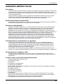
INFORMATIONS SUR LA SÉCURITÉ . . . . . . . . . . . . . . . . . . . . . . . . . . . . . . . . . . . . .23
Caractéristiques . . . . . . . . . . . . . . . . . . . . . . . . . . . . . . . . . . . . . . . . . . . . . . . . . . . . . .23
Modèles d'orifices VESA pour téléviseur : . . . . . . . . . . . . . . . . . . . . . . . . . . . . . . . . . . . 23
Dimensions . . . . . . . . . . . . . . . . . . . . . . . . . . . . . . . . . . . . . . . . . . . . . . . . . . . . . . . . . . . . . . . 24
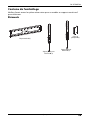
Outils nécessaires. . . . . . . . . . . . . . . . . . . . . . . . . . . . . . . . . . . . . . . . . . . . . . . . . . . . .24
Contenu de l'emballage. . . . . . . . . . . . . . . . . . . . . . . . . . . . . . . . . . . . . . . . . . . . . . .25
Éléments . . . . . . . . . . . . . . . . . . . . . . . . . . . . . . . . . . . . . . . . . . . . . . . . . . . . . . . . . . . . . . . . . . 25
Sachet de visserie pour le téléviseur . . . . . . . . . . . . . . . . . . . . . . . . . . . . . . . . . . . . . . . . 26
Instructions d’installation . . . . . . . . . . . . . . . . . . . . . . . . . . . . . . . . . . . . . . . . . . . . .27
ÉTAPE 1 : Déterminer si le téléviseur a un dos plat ou de forme irrégulière ou
est obstrué . . . . . . . . . . . . . . . . . . . . . . . . . . . . . . . . . . . . . . . . . . . . . . . . . . . . . . . . . . . . . . . . 27
ÉTAPE 2 - Sélectionner les vis, les rondelles et les entretoises . . . . . . . . . . . . . . . . 28
ÉTAPE 3 - Fixation des caches en plastique à la plaque murale . . . . . . . . . . . . . . . 29
ÉTAPE 4 - Option 1 : Fixation des ferrures sur un téléviseur à dos plat . . . . . . . . 30
ÉTAPE 4 - Option 2 : Fixation de la visserie sur un téléviseur à dos de forme
irrégulière ou obstrué. . . . . . . . . . . . . . . . . . . . . . . . . . . . . . . . . . . . . . . . . . . . . . . . . . . . . .32
ÉTAPE 5 - Déterminer l’emplacement du montage mural. . . . . . . . . . . . . . . . . . . . 34
ÉTAPE 6 - Option 1 : Installation sur un mur à montants en bois. . . . . . . . . . . . . . 35
ÉTAPE 6 - Option 2 : Montage sur un mur en béton ou en blocs de béton . . . . 37
ÉTAPE 7 - Fixation du téléviseur à la plaque murale . . . . . . . . . . . . . . . . . . . . . . . . . 39
Si pour une raison quelconque il et nécessaire de retirer le téléviseur de la
plaque murale. . . . . . . . . . . . . . . . . . . . . . . . . . . . . . . . . . . . . . . . . . . . . . . . . . . . . . . . . . . . . 40
GARANTIE LIMITÉE D’UN AN . . . . . . . . . . . . . . . . . . . . . . . . . . . . . . . . . . . . . . . . . .41

3
DX-DTVMFP23
www.dynexproducts.com
ENGLISH
SAFETY INFORMATION
INSTRUCTIONS
CAUTION: Do not use this product for any purpose not explicitly specified by Dynex.
• Improper installation may cause property damage or personal injury. If you do not
understand these directions, or have doubts about the safety of the installation,
contact Customer Service or call a qualified contractor. Dynex is not responsible for
damage or injury caused by incorrect installation or use.
• The weight of your TV must not exceed 165 lbs. (75 kg). The wall must be capable of
supporting five times the weight of your TV and wall mount combined.
• This product contains small items that could be a choking hazard if swallowed. Keep
these items away from young children!
SAVE THESE INSTRUCTIONS
Features
• Supports TVs 37"– 90" and up to 165 lbs (75 kg)
• Low-profile design is lighter for easier installation
• Compatible with VESA patterns from 200 × 200 up to 600 × 400 with all common
sizes in between
• Sturdy steel construction for years of dependable use
• Full assortment of mounting hardware included for a wide range of TVs
VESA TV screw hole patterns
Your wall mount works with the following VESA TV screw hole patterns:
200 × 200 mm (7.9 × 7.9") 400 × 300 mm (15.7 × 11.8")
300 × 200 mm (11.8 × 7.9") 400 × 400 mm (15.7 × 15.7")
300 × 300 mm (11.8 × 11.8") 500 × 400 mm (19.7 × 15.7")
400 × 200 mm (15.7 × 7.9") 600 × 400 mm (23.6 × 15.7")

4
www.dynexproducts.com
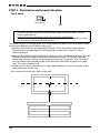
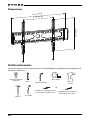
Dimensions
Tools needed
You will need the following tools to assemble your new TV wall mount:
2
7
.
2
i
n.
(
6
9
2
m
m
)
2
3
.
6
i
n
.
(
6
0
0
m
m
)
16.9 in. (430 mm)
6
.
1
i
n
.
(
1
5
4
m
m
)
Edge-to-edge stud finder
Phillips screwdriver
Measuring tape
Drill
3/16 in. (5 mm) wood drill bit
(for wood stud wall)
Hammer
Pencil
Socket wrench
OR
3/8 in. (10 mm) masonry drill bit (for
concrete wall)

5
DX-DTVMFP23
www.dynexproducts.com
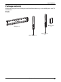
Package contents
Make sure that you have all the parts and hardware necessary to assemble your new TV
wall mount.
Parts
A Wall plate (1)
B Left TV bracket (1)
C Right TV bracket
(1)
D Plastic covers
(2)

6
www.dynexproducts.com
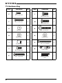
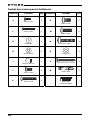
TV Hardware Bag
LABEL HARDWARE QTY. LABEL HARDWARE QTY.
E 4 L 4
F 4 M 4
G 8 N 4
H 4 O 4
I 4 P 4
J 4 Q 4
K 41
M4 × 12 mm screw
M8 × 16 mm screw
M4 × 35 mm screw
M8 × 20 mm screw
M4 washer
M8 × 36 mm screw
M6/M8 washer
Lag bolt washer
Universal spacer
5/16" × 2 3/4" lag bolt
M6 × 12 mm screw
Concrete anchor
M6 × 35 mm screw
Magnetic removable
level

7
DX-DTVMFP23
www.dynexproducts.com
Installation instructions
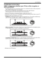
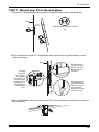
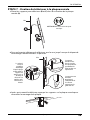
STEP 1- Determine whether your TV has a flat, irregular, or
obstructed back
1 Carefully place your TV screen face-down on a cushioned, clean surface to protect
the screen from damages and scratches.
2 If your TV has a table-top stand attached, remove the stand. See the
documentation that came with your TV for instructions.
3 Lay the TV brackets, oriented vertically, on the back of your TV.
4 Align the screw holes in the TV brackets with the mounting screw holes on your TV.
5 Identify which type of back your TV has:
• Flat back: The brackets lay flush against the back of your TV and do not block any
jacks. You do not need spacers when assembling the wall mount.
• Obstructed back: The brackets block one or more of the jacks on the back of your
TV. You need spacers when assembling the wall mount.
• Irregularly-shaped back: There is a gap between a bracket and some part of the
back of your TV. You need spacers when assembling the wall mount.
6 Remove the TV brackets.

8
www.dynexproducts.com
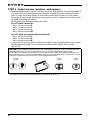
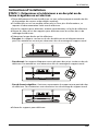
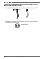
STEP 2 - Select screws, washers, and spacers
1 Select the hardware for your TV (screws, washers, and spacers). A limited number of
TVs come with mounting hardware included. (If there are screws that came with
your TV, they are almost always in the holes on the back of your TV.) If you don't
know the correct length of the mounting screws your TV requires, test various sizes
by hand-threading the screws.
Select one of the following types of screws:
For a TV with a flat back:
• M4 × 12 mm screws (E)
• M6 × 12 mm screws (J)
• M8 × 16 mm screws (L)
• M8 × 20 mm screws (M)
For a TV with an irregular/obstructed back:
• M4 × 35 mm screws (F)
• M6 × 35 mm screws (K)
• M8 × 36 mm screws (N)
If you use M4 screws, select the M4 washer (G) or if you use M6 or M8 screws, select
the M6/M8 washer (H). For an irregular or obstructed TV back, also use the
spacers (I).
2 Remove the screws from the holes in the back of your TV.
CAUTION: To avoid potential personal injuries and property damage, make sure that there are
adequate threads to secure the brackets to your TV. If you encounter resistance, stop
immediately and contact customer service. Use the shortest screw and spacer combination to
accommodate your TV. Using hardware that is too long may damage your TV. However, using a
screw that is too short may cause your TV to fall from the mount.
Screw is
too long
Screw fits
correctly
Screw is
too short

9
DX-DTVMFP23
www.dynexproducts.com
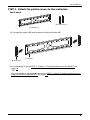
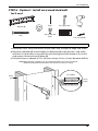
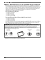
STEP 3 - Attach the plastic covers to the wall plate
You’ll need
1 Fit the plastic covers (D) over the ends of the wall plate (A).
2 For a flat back TV, go to STEP 4 - Option 1: Attach hardware to a flat back TV on
page 10.
-OR-
For an irregular or obstructed back, go to STEP 4 - Option 2: Attach hardware to an
irregular or obstructed back TV on page 12.
D - Plastic covers (2)
A - Wall plate (1)
D - Plastic cover
A - Wall plate

10
www.dynexproducts.com
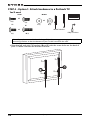
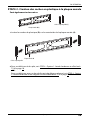
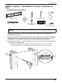
STEP 4 - Option 1: Attach hardware to a flat back TV
You’ll need
1 Align the left and right TV brackets (B and C) with the screw holes on the back of
your TV. Make sure that the brackets are level.
Note: If you plan to use a 5° tilt with a larger TV (42”+), we suggest using spacers with the
mounting brackets so that the bottom of your TV does not touch the wall.
G (4)
E (4)
Phillips screwdriver
OR
OR
J (4)
H (4)
OR
L (4)
Level
OR
M (4)
OR
Screws Washers
B and C TV brackets

11
DX-DTVMFP23
www.dynexproducts.com
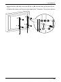
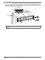
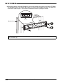
2 Install washers (G or H), and screws (E, J, L, or M) into the holes in the back of your
TV.
3 Tighten the screws until they are snug against the TV brackets. Do not over tighten.
or
or

12
www.dynexproducts.com
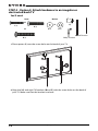
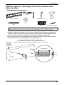
STEP 4 - Option 2: Attach hardware to an irregular or
obstructed back TV
You’ll need
1 Place spacers (I) over the screw holes on the back of your TV.
2 Align the left and right TV brackets (B and C) with the screw holes on the back of
your TV. Make sure that the brackets are level.
G (8)
F (4)
I (4)
B and C TV brackets
H (4)
OR
OR
K (4)
N (4)
OR
Screws
Washers
Phillips screwdriver

13
DX-DTVMFP23
www.dynexproducts.com
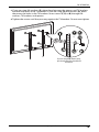
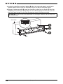
3 If you are using M4 washers (G), place them between the spacers and TV brackets
and over the holes in the TV brackets. If you are using M6/M8 washers (H), place
them over the holes in the TV brackets. Insert screws (F, K, or N) through the
washers, TV brackets, and spacers.
4 Tighten the screws until they are snug against the TV brackets. Do not over tighten.
or
or
If you are using M4 (G) washers (only),
place them both in front of and behind
the brackets.

14
www.dynexproducts.com
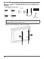
STEP 5 - Determine wall-mount location
You’ll need
The center of your TV will be offset .8 in. lower than the center of the wall plate on the
wall-mount. Before you drill holes in the wall:
1 Measure the distance from the bottom of your TV to the center point halfway
between the top and bottom mounting holes on the back of your TV. This is
measurement a.
2 Measure the distance from the floor to where you want the bottom of your TV to be
placed on the wall. Keep in mind that the bottom of your TV should be placed
above any furniture (such as entertainment centers or TV stands). Your TV should
also be above items placed on top of the furniture (like a Blu-ray player or cable
box). This measurement is b.
3 Add a + b. The total measurement is the height where you want the center of the
wall plate to be on the wall.
4 Use a pencil to mark this spot on the wall.
Notes:
• For more detailed information on determining where to drill your holes, visit our
online height-finder at:
http://mf1.bestbuy.selectionassistant.com/index.php/heightfinder
• Your TV should be high enough so your eyes are level with the middle of the screen.
This is normally 40 to 60 in. from the ground.
Measuring tape
Pencil
A
B
A

15
DX-DTVMFP23
www.dynexproducts.com
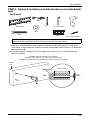
STEP 6 - Option 1: Install on a wood stud wall
You’ll need
1 Locate the studs. Verify the centers of the studs with an edge-to-edge stud finder.
2 Align the wall plate (A) at the height you determined in the previous step, make
sure that it is level, then use a pencil to mark the lag bolt hole locations (4) on the
stud centers. Remove the wall plate (A).
3 Drill pilot holes to a depth of 2 in. (50 mm) using a 3/16 in. (5 mm) diameter drill bit.
Note: Any drywall covering the wall must not exceed 5/8 in. (16 mm).
Edge-to edge stud
finder
P (4)
Pencil
Drill
3/16" wood drill bit
1/2" socket wrench
Level
O (4)
Wall plate (A)
Wood
stud
2 in. (50 mm)
3/16 in.
(5 mm)
- Minimum wood stud size: common 2 x 4 in. (51 x 102 mm) nominal 11/2 x 31/2 in. (38 x 89 mm).
- Minimum spacing between horizontal fasteners cannot be less than 16 in. (40 cm)

16
www.dynexproducts.com
4 Align the wall plate (A) with the pilot holes, insert the lag bolts (P) through the lag
bolt washers (O), then through the holes in the wall plate. Tighten the lag bolts only
until they are firm against the wall plate.
CAUTION: Avoid potential injuries or property damage! DO NOT over-tighten the lag
bolts (P).
Level
Wood stud

17
DX-DTVMFP23
www.dynexproducts.com
STEP 6 - Option 2: Install on a solid concrete or concrete block
wall
You’ll need
1 Align the wall plate (A) at the height you determined in the previous step, make
sure that it is level, then use a pencil to mark the lag bolt hole locations (4). Remove
the wall plate (A).
2 Drill pilot holes to a depth of 2.36 in. (60 mm) using a 3/8 in. (10 mm) diameter
masonry drill bit.
CAUTION: To prevent property damage or personal injury, never drill into mortar
between blocks. Mount the wall plate directly onto the concrete surface.
P (4)
Pencil
Drill
1/2" socket wrench
Level
O (4)
Wall plate (A)
Q (4)
3/8 in. masonry drill bit
Concrete
wall
2.36 in. (60 mm)
3/8 in.
(10 mm)
* Minimum solid concrete thickness: 8 in. (203mm).
* Minimum concrete block size: 8 x 8 x 16 in. (203 x 203 x 406 mm).
The minimum distance between the top two fasteners cannot be less than 16 in. (40 cm)

18
www.dynexproducts.com
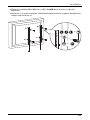
3 Insert the concrete wall anchors (Q) into the pilot holes and use a hammer to make
sure the anchors are flush with the concrete surface.
4 Align the wall plate (A) with the anchors, insert the lag bolts (P) through the lag
bolt washers (O), then through the holes in the wall plate. Tighten the lag bolts only
until they are firm against the wall plate.
CAUTION: Avoid potential injuries or property damage! DO NOT over-tighten the lag
bolts (P).
Concrete wall
Level

19
DX-DTVMFP23
www.dynexproducts.com
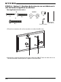
STEP 7 - Mount your TV to the wall plate
1 Place the TV brackets (B and C) into the slotted flanges of the wall plate (A).
2 Push the bottom of your TV toward the wall until the spring self-locking system
clicks into place.
3 Press the brackets after you mount your TV to the wall plate to lock the assembly to
the wall plate.
HEAVY! You will need assistance with this
step.
Wall
Wall
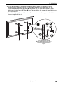
The pendents have a
magnetic button on
the end so that you
can stick them to
the brackets to keep
them out of sight.
The spring
self-locking
system engages
the wall plate
when you press on
the brackets after
mounting your TV.
This prevents your
TV from jarring
loose.
The brackets must
engage the slotted
flanges of the wall
plate to hold your
TV in place.

20
www.dynexproducts.com
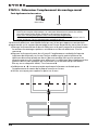
If you ever need to remove your TV from the wall plate
1 Grasp your TV by the bottom edge, then pull down on the locking cords and pull
the bottom of your TV out from the wall.
2 Release the locking cords and lift the top of your TV from the wall bracket.
HEAVY! You will need
assistance with this step.
La page charge ...
La page charge ...
La page charge ...
La page charge ...
La page charge ...
La page charge ...
La page charge ...
La page charge ...
La page charge ...
La page charge ...
La page charge ...
La page charge ...
La page charge ...
La page charge ...
La page charge ...
La page charge ...
La page charge ...
La page charge ...
La page charge ...
La page charge ...
La page charge ...
La page charge ...
La page charge ...
-
 1
1
-
 2
2
-
 3
3
-
 4
4
-
 5
5
-
 6
6
-
 7
7
-
 8
8
-
 9
9
-
 10
10
-
 11
11
-
 12
12
-
 13
13
-
 14
14
-
 15
15
-
 16
16
-
 17
17
-
 18
18
-
 19
19
-
 20
20
-
 21
21
-
 22
22
-
 23
23
-
 24
24
-
 25
25
-
 26
26
-
 27
27
-
 28
28
-
 29
29
-
 30
30
-
 31
31
-
 32
32
-
 33
33
-
 34
34
-
 35
35
-
 36
36
-
 37
37
-
 38
38
-
 39
39
-
 40
40
-
 41
41
-
 42
42
-
 43
43


Dynex DX-DTVMFP23 Guide d'installation
- Catégorie
- Supports muraux à panneau plat
- Taper
- Guide d'installation
- Ce manuel convient également à
dans d''autres langues
- English: Dynex DX-DTVMFP23 Installation guide
Documents connexes
-
Dynex DX-HTMF1620 Guide d'installation rapide
-
Dynex DX-DTVMFP12 Manuel utilisateur
-
-
-
Best Buy Dynex DX-HTVMM1703-C Guide d'installation
-
-
-
-
-
