Whirlpool WFG775H0HB Guide d'installation
- Catégorie
- Cuisinières
- Taper
- Guide d'installation

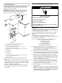
INSTALLATION INSTRUCTIONS
30" (76.2 CM) FREESTANDING GAS RANGES
INSTRUCTIONS D’INSTALLATION POUR CUISINIÈRES AU
GAZ AUTOPORTANTES DE 30 po (76,2 cm)
INSTRUCCIONES DE INSTALACIÓN ESTUFAS ELÉCTRICAS
INDEPENDIENTES DE 30" (76,2 cm)
W11085334B
Table of Contents
IMPORTANT:
Installer: Leave installation instructions with the homeowner.
Homeowner: Keep installation instructions for future reference.
RANGE SAFETY .............................................................................2
INSTALLATION REQUIREMENTS ................................................. 3
Tools and Parts .............................................................................3
Location Requirements ................................................................4
Electrical Requirements ...............................................................5
Gas Supply Requirements ...........................................................6
INSTALLATION INSTRUCTIONS ................................................... 7
Unpack Range..............................................................................7
Install Anti-Tip Bracket .................................................................8
Make Gas Connection .................................................................8
Install Griddle .............................................................................10
Verify Anti-Tip Bracket Is Installed
and Engaged ..............................................................................11
Level Range ................................................................................11
Electronic Ignition System .........................................................12
Warming Drawer or Premium Storage Drawer ..........................13
Oven Door ..................................................................................14
Complete Installation .................................................................14
GAS CONVERSIONS ....................................................................15
Propane Gas Conversion ...........................................................15
Natural Gas Conversion .............................................................18

2
RANGE SAFETY
You can be killed or seriously injured if you don't immediately
You
can be killed or seriously injured if you don't
follow
All safety messages will tell you what the potential hazard is, tell you how to reduce the chance of injury, and tell you what can
happen if the instructions are not followed.
Your safety and the safety of others are very important.
We have provided many important safety messages in this manual and on your appliance. Always read and obey all safety
messages.
This is the safety alert symbol.
This symbol alerts you to potential hazards that can kill or hurt you and others.
All safety messages will follow the safety alert symbol and either the word “DANGER” or “WARNING.”
These words mean:
follow instructions.
instructions.
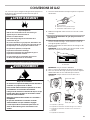
DANGER
WARNING
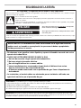
WARNING: If the information in these instructions is not followed exactly, a fire or
explosion may result causing property damage, personal injury or death.
– Do not store or use gasoline or other flammable vapors and liquids in the vicinity of this
or any other appliance.
– WHAT TO DO IF YOU SMELL GAS:
•
Do not try to light any appliance.
•
Do not touch any electrical switch.
•
Do not use any phone in your building.
•
Immediately call your gas supplier from a neighbor's phone. Follow the gas supplier's
instructions.
•
If you cannot reach your gas supplier, call the fire department.
– Installation and service must be performed by a qualified installer, service agency or
the gas supplier.
IMPORTANT: Do not install a ventilation system that blows air downward toward this gas cooking appliance. This type of
ventilation system may cause ignition and combustion problems with this gas cooking appliance resulting in personal injury or
unintended operation.
WARNING: Gas leaks cannot always be detected by smell.
Gas suppliers recommend that you use a gas detector approved by UL or CSA.
For more information, contact your gas supplier.
If a gas leak is detected, follow the “What to do if you smell gas” instructions.

3
In the State of Massachusetts, the following installation instructions apply:
■ Installations and repairs must be performed by a qualified or licensed contractor, plumber, or gas fitter qualified or licensed by
the State of Massachusetts.
■ Acceptable Shut-off Devices: Gas Cocks and Ball Valves installed for use shall be listed.
■ A flexible gas connector, when used, must not exceed 4 feet (121.9 cm).
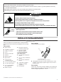
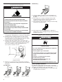
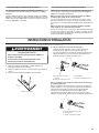
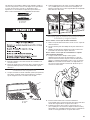
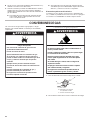
Tip Over Hazard
A child or adult can tip the range and be killed.
Install anti-tip bracket to floor or wall per installation instructions.
Slide range back so rear range foot is engaged in the slot of the anti-tip bracket.
Re-engage anti-tip bracket if range is moved.
Do not operate range without anti-tip bracket installed and engaged.
Failure to follow these instructions can result in death or serious burns to children and adults.
Anti-Tip
Bracket
To verify the anti-tip bracket is installed and engaged:
• Slide range forward.
• Look for the anti-tip bracket securely attached to floor or wall.
• Slide range back so rear range foot is under anti-tip bracket.
• See installation instructions for details.
Range Foot
WARNING
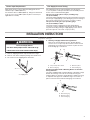
INSTALLATION REQUIREMENTS
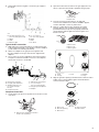
Tools and Parts
Gather the required tools and parts before starting installation.
Read and follow the instructions provided with any tools listed
here.
Tools needed
■ Tape measure
■ Flat-blade screwdriver
■ Phillips screwdriver
■ Level
■ Hand or electric drill
■ Hammer
■ Wrench or pliers
■ Pipe wrench
■ 15/16" (24 mm)
combination wrench
■ 1/4" (6.4 mm) drive ratchet
■ 3/8" (95 mm) nut driver
■ 1/8" (3.2 mm) drill bit
(for wood floors)
■ Marker or pencil
†
®
QUADREX is a registered trademark of NLW Holdings, Inc.
■ Pipe-joint compound
resistant to propane gas
■ Noncorrosive leak-
detection solution
For Propane/Natural
Gas Conversions
■ 3/8" (95 mm) combination
wrench
■ 1/2" (12.7 mm) combination
wrench
■ 5/8" (16 mm) combination
wrench
■ 7 mm (9/32") nut driver
■ Quadrex
®†
or Phillips
screwdriver
■ Masking tape
Parts supplied
Check that all parts are included.
A. Anti-tip bracket
B. #12 x 1
5
⁄
8
" (41.3 mm) screws (2)
■ Anti-tip bracket must be securely mounted to floor or wall.
Thickness of flooring may require longer screws to anchor
bracket to floor.
Parts needed
Check local codes and consult gas supplier. Check existing gas
supply and electrical supply. See the “Electrical Requirements”
and “Gas Supply Requirements” sections.
A
B

4
Location Requirements
IMPORTANT: Observe all governing codes and ordinances. Do
not obstruct flow of combustion and ventilation air.
■ It is the installer’s responsibility to comply with installation
clearances specified on the model/serial rating plate. The
model/serial rating plate is located on the oven frame behind
the top right side of the oven door.
■ Recessed installations must provide complete enclosure of
the sides and rear of the range.
■ All openings in the wall or floor where range is to be installed
must be sealed.
■ Do not seal the range to the side cabinets.
■ Cabinet opening dimensions that are shown must be used.
Given dimensions are minimum clearances.
■ The floor anti-tip bracket must be installed. To install the
antitip bracket shipped with the range, see the “Install Anti-
Tip Bracket” section.
■ Grounded electrical supply is required. See the “Electrical
Requirements” section.
■ Proper gas supply connection must be available. See the
“Gas Supply Requirements” section.
■ Contact a qualified floor covering installer to check that the
floor covering can withstand at least 200°F (93°C).
■ Use an insulated pad or 1/4" (6.4 mm) plywood under range
if installing range over carpeting.
IMPORTANT: To avoid damage to your cabinets, check with
your builder or cabinet supplier to make sure that the materials
used will not discolor, delaminate, or sustain other damage. This
oven has been designed in accordance with the requirements
of UL and CSA International and complies with the maximum
allowable wood cabinet temperatures of 194°F (90°C).
Mobile Home Additional Installation Requirements
The installation of this range must conform to the Manufactured
Home Construction and Safety Standard, Title 24 CFR,
Part 3280 (formerly the Federal Standard for Mobile Home
Construction and Safety, Title 24, HUD Part 280). When such
standard is not applicable, use the Standard for Manufactured
Home Installations, ANSI A225.1/NFPA 501A or with local codes.
In Canada, the installation of this range must conform with the
current standards CAN/CSA-Z240, latest edition, or with local
codes.
Mobile home installations require:
■ When this range is installed in a mobile home, it must be
secured according to the instructions in this document.
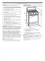
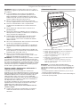
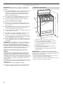
Product Dimensions
A. 27
3
/
8
" (69.5 cm) max. depth with handle
B. 46
1
/
2
" (118.1 cm) overall height (max.) with leveling legs
screwed all the way in*
C. 36" (91.4 cm) cooktop height (max.) with leveling legs
screwed all the way in*
D. 29
7
⁄
8
" (75.9 cm) width
E. 25
5
/
16
" (64.3 cm) depth. Back of range to front of cooktop**
F. Model/serial rating plate (located on the oven frame behind
the top right side of the oven door)
IMPORTANT: Range must be level after installation. Follow the
instructions in the “Level Range” section. Using the cooktop as a
reference for leveling the range is not recommended.
* Range can be raised approximately 1" (2.5 cm) by adjusting
the leveling legs.
** Front of door and drawer may extend farther forward,
depending on styling.
F
D
C
B
E
A

5
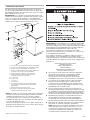
Cabinet Dimensions
Cabinet opening dimensions shown are for 25" (64.0 cm)
countertop depth, 24" (61.0 cm) base cabinet depth and
36" (91.4 cm) countertop height.
IMPORTANT: If installing a range hood or microwave hood
combination above the range, follow the range hood or
microwave hood combination installation instructions for
dimensional clearances above the cooktop surface.
A. 18" (45.7 cm) upper side cabinet to countertop
B. 13" (33 cm) max. upper cabinet depth
C. 30" (76.2 cm) min. opening width
D. For minimum clearance to top of cooktop, see NOTE*.
E. 30¹⁄
8
" (76.5 cm) min. opening width
F. The shaded areas are recommended for installation of rigid
gas pipe.
G. 11" (27.9 cm)
H. 17" (43.2 cm)
I. 2" (5.1 cm)
J. 4¹⁄
2
" (11.4 cm)
K. 3" (7.6 cm) min. clearance from both sides of range to side
wall or other combustible material.
L. Grounded outlet
M. Cabinet door or hinges should not extend into the cutout.
* NOTE: 24" (61.0 cm) minimum when bottom of wood or
metal cabinet is covered by not less than 1/4" (6.4 mm) flame
retardant millboard covered with not less than No. 28 MSG
sheet steel, 0.015" (0.4 mm) stainless steel, 0.024" (0.6 mm)
aluminum or 0.020" (0.5 mm) copper.
30" (76.2 cm) minimum clearance between the top of the
cooking platform and the bottom of an uncovered wood or
metal cabinet.
Electrical Requirements
IMPORTANT: The range must be electrically grounded in
accordance with local codes and ordinances, or in the absence
of local codes, with the National Electrical Code, ANSI/NFPA 70
or Canadian Electrical Code, CSA C22.1.
This range is equipped with an electronic ignition system that
will not operate if plugged into an outlet that is not properly
polarized.
If codes permit and a separate ground wire is used, it is
recommended that a qualified electrical installer determine that
the ground path is adequate.
A copy of the above code standards can be obtained from:
National Fire Protection Association
1 Batterymarch Park
Quincy, MA 02169-7471
CSA International
8501 East Pleasant Valley Road
Cleveland, OH 44131-5575
■ A 120 volt, 60 Hz., AC only, 15-amp fused, electrical circuit
is required. A time-delay fuse or circuit breaker is also
recommended. It is recommended that a separate circuit
serving only this range be provided.
■ Electronic ignition systems operate within wide voltage limits,
but proper grounding and polarity are necessary. Check that
the outlet provides 120-volt power and is correctly grounded.
■ This gas range is not required to be plugged into a GFCI
(Ground-Fault Circuit Interrupter) outlet. It is recommended
that you not plug an electric spark ignition gas range or any
other major appliance into a GFCI wall outlet as it may cause
the GFCI to trip during normal cycling.
■ Performance of this range will not be affected if operated
on a GFCI-protected circuit. However, occasional nuisance
tripping of the GFCI breaker is possible due to the normal
operating nature of electronic gas ranges.
■ The wiring diagram is located on the back of the range in a
clear plastic bag.
NOTE: The metal chassis of the range must be grounded in
order for the control panel to work. If the metal chassis of the
range is not grounded, no keypads will operate. Check with
a qualified electrician if you are in doubt as to whether the
metal chassis of the range is grounded.
Electrical Shock Hazard
Plug into a grounded 3 prong outlet.
Do not remove ground prong.
Do not use an adapter.
Do not use an extension cord.
Failure to follow these instructions can result in death,
fire, or electrical shock.
WARNING
M
H
A
B
C
D
E
L
G
I
K
J
F

6
Gas Supply Requirements
Observe all governing codes and ordinances.
IMPORTANT: This installation must conform with all local codes
and ordinances. In the absence of local codes, installation must
conform with American National Standard, National Fuel Gas
Code ANSI Z223.1, latest edition or CAN/CGA B149, latest
edition.
IMPORTANT: Leak testing of the range must be conducted
according to the manufacturer’s instructions.
Type of Gas
Natural gas:
■ This range is factory set for use with Natural gas. See the
“Gas Conversions” section. The model/serial rating plate
located on the oven frame behind the top right side of the
oven door has information on the types of gas that can be
used. If the types of gas listed do not include the type of gas
available, check with the local gas supplier.
Propane gas conversion:
Conversion must be done by a qualified service technician.
No attempt shall be made to convert the appliance from the gas
specified on the model/serial rating plate for use with a different
gas without consulting the serving gas supplier. See the “Gas
Conversions” section.
Gas Supply Line
■ Provide a gas supply line of 3/4" (19 mm) rigid pipe to the
range location. A smaller size pipe on longer runs may
result in insufficient gas supply. With propane gas, piping or
tubing size can be 1/2" (13 mm) minimum. Usually, propane
gas suppliers determine the size and materials used in the
system.
NOTE: Pipe-joint compounds that resist the action of
propane gas must be used. Do not use TEFLON
®†
tape.
†
®
TEFLON is a registered trademark of Chemours.
Flexible metal appliance connector:
■ If local codes permit, a new CSA design-certified, 4 to
5 ft (122 to 152.4 cm) long, 1/2" (13 mm) or 3/4" (19 mm)
I.D., flexible metal appliance connector may be used for
connecting range to the gas supply line.
■ A 1/2" (13 mm) male pipe thread is needed for connection to
the female pipe threads of the inlet to the appliance pressure
regulator.
■ Do not kink or damage the flexible metal tubing when
moving the range.
Rigid pipe connection:
The rigid pipe connection requires a combination of pipe fittings
to obtain an in-line connection to the range. The rigid pipe must
be level with the range connection. All strains must be removed
from the supply and fuel lines so range will be level and in line.
■ Must include a shut-off valve:
Install a manual gas line shut-off valve in an easily accessible
location. Do not block access to shut-off valve. The valve is
for turning on or shutting off gas to the cooktop.
A. Gas supply line
B. Shut-off valve open position
C. To range
Gas Pressure Regulator
The gas pressure regulator supplied with this range must be
used. The inlet pressure to the regulator should be as follows for
proper operation:
Natural gas:
Minimum pressure: 5" (12.7 cm) WCP
Maximum pressure: 14" (35.5 cm) WCP
Propane gas:
Minimum pressure: 11" (27.9 cm) WCP
Maximum pressure: 14" (35.5 cm) WCP
Contact local gas supplier if you are not sure about the inlet
pressure.
WARNING
Explosion Hazard
Use a new CSA International approved gas supply line.
Install a shut-off valve.
Securely tighten all gas connections.
If connected to propane, have a qualified person make
sure gas pressure does not exceed 14" (36 cm) water
column.
Examples of a qualified person include:
licensed heating personnel,
authorized gas company personnel, and
authorized service personnel.
Failure to do so can result in death, explosion, or fire.
A
B
C

7
Burner Input Requirements
Input ratings shown on the model/serial rating plate are for
elevations up to 2,000 ft (609.6 m).
For elevations above 2,000 ft (609.6 m), ratings are reduced at
a rate of 4% for each 1,000 ft (304.8 m) above sea level (not
applicable for Canada).
Gas Supply Pressure Testing
Gas supply pressure for testing regulator must be at least
1" (2.5 cm) water column pressure above the manifold pressure
shown on the model/serial rating plate.
Line pressure testing above 1/2 psi (3.5 kPa) gauge
14" (35.6 cm WCP)
The range and its individual shut-off valve must be disconnected
from the gas supply piping system during any pressure testing of
that system at test pressures in excess of 1/2 psi (3.5 kPa).
Line pressure testing at 1/2 psi (3.5 kPa) gauge
14" (35.6 cm WCP) or lower
The range must be isolated from the gas supply piping
system by closing its individual manual shut-off valve during
any pressure testing of the gas supply piping system at test
pressures equal to or less than 1/2 psi (3.5 kPa).
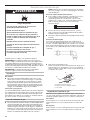
INSTALLATION INSTRUCTIONS
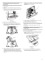
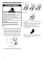
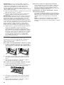
Unpack Range
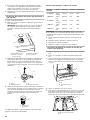
1. Remove shipping materials, tape and film from range.
2. Remove oven racks and parts package from inside oven.
3. Do not remove the shipping base at this time.
A. Shipping base
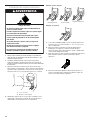
4. On Ranges Equipped with a Storage Drawer:
Remove the storage drawer. See the “Storage Drawer”
section. Use a 1/4" (6.4 mm) drive ratchet to lower the rear
leveling legs one-half turn. Use a wrench or pliers to lower
front leveling legs one-half turn.
A. 1/4" (6.4 mm) drive ratchet
B. Rear leveling leg
C. Wrench or pliers
D. Front leveling leg
On Ranges Equipped with a Warming Drawer or Premium
Storage Drawer:
On ranges equipped with a warming drawer or premium storage
drawer, the rear legs cannot be accessed by removing the
warming drawer or premium storage drawer. It will be necessary
to adjust the rear legs from outside the range. Use wrench or
pliers to lower the front and rear leveling legs one-half turn.
A. Rear leveling leg
B. Wrench or pliers
C. Front leveling leg
WARNING
Excessive Weight Hazard
Use two or more people to move and install range.
Failure to do so can result in back or other injury.
A
C
D
A
B
B
C
A

8
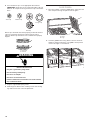
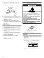
Install Anti-Tip Bracket
1. Remove the anti-tip bracket from where it is taped inside the
storage drawer, warming drawer, or premium storage drawer.
2. Determine which mounting method to use: floor or wall.
If you have a stone or masonry floor, you can use the wall
mounting method. If you are installing the range in a mobile
home, you must secure the range to the floor.
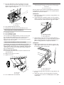
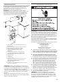
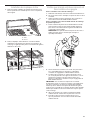
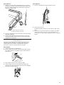
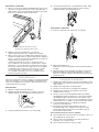
3. Determine and mark centerline of the cutout space. The
mounting can be installed on either the left side or right side
of the cutout. Position mounting bracket against the wall in
the cutout so that the V-notch of the bracket is 12
9
⁄
16
"
(31.9 cm) from centerline as shown.
A. 12
9
⁄
16
" (31.9 cm)
B. Bracket V-notch
4. Drill two 1/8" (3 mm) holes that correspond to the bracket
holes of the determined mounting method. See the following
illustrations.
Floor Mounting
Rear position
Front position Diagonal (2 options)
Wall Mounting
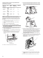
5. Using the Phillips screwdriver, mount anti-tip bracket to
the wall or floor with the two #12 x 1
5
⁄
8
" (41.3 mm) screws
provided.
6. Move range close enough to opening to allow for final
gas and electrical connections. Remove shipping base,
cardboard or hardboard from under range.
7. Move range into its final location, making sure rear leveling
leg slides into anti-tip bracket.
8. Move range forward onto shipping base, cardboard, or
hardboard to continue installing the range using the following
installation instructions.
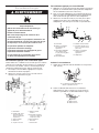
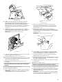
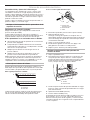
Make Gas Connection
Typical rigid pipe connection
A combination of pipe fittings must be used to connect the
range to the existing gas line. Your connections may be different,
according to the supply line type, size, and location.
1. Apply pipe-joint compound made for use with propane gas
to all pipe thread connections.
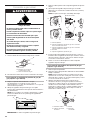
WARNING
Tip Over Hazard
A child or adult can tip the range and be killed.
Install anti-tip bracket to floor or wall per installation
instructions.
Slide range back so rear range foot is engaged in the
slot of the anti-tip bracket.
Re-engage anti-tip bracket if range is moved.
Do not operate range without anti-tip bracket installed
and engaged.
Failure to follow these instructions can result in death
or serious burns to children and adults.
WARNING
Explosion Hazard
Use a new CSA International approved gas supply line.
Install a shut-off valve.
Securely tighten all gas connections.
If connected to propane, have a qualified person make
sure gas pressure does not exceed 14" (36 cm) water
column.
Examples of a qualified person include:
licensed heating personnel,
authorized gas company personnel, and
authorized service personnel.
Failure to do so can result in death, explosion, or fire.
Centerline
B
A

9
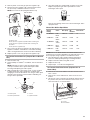
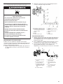
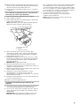
2. Using a pipe wrench to tighten, connect the gas supply to
the range.
A. Gas pressure regulator
B. 90° elbow (must have 1/2"
(12.7 mm) male pipe thread)
C. Nipple
D. Union
E. Black iron pipe
F. Manual gas shut-off valve
G. 1/2" (12.7 mm) or
3/4" (19.1 mm) gas pipe
H. Nipple
I. Union
J. 90° elbow
Typical flexible connection
1. Apply pipe-joint compound made for use with propane gas
to the smaller thread ends of the flexible connector adapters
(see B and G in the following illustration).
2. Attach one adapter to the gas pressure regulator and
the other adapter to the gas shut-off valve. Tighten both
adapters.
3. Use a 15/16" (23.8 mm) combination wrench and channel
lock pliers to attach the flexible connector to the adapters.
Check that connector is not kinked.
A. Gas pressure regulator
B. Use pipe-joint compound
C. Adapter (must have 1/2"
[12.7 mm] male pipe
thread)
D. Flexible connector
E. Manual gas shut-off valve
F. 1/2" (12.7 mm) or
3/4" (19.1 mm) gas pipe
G. Use pipe-joint compound
H. Adapter
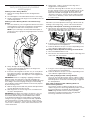
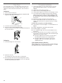
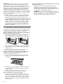
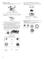
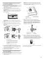
2. Open the manual shut-off valve in the gas supply line. The
valve is open when the handle is parallel to the gas pipe.
A. Closed valve
B. Open valve
3. Test all connections by brushing on an approved
noncorrosive leak-detection solution. If bubbles appear,
a leak is indicated. Correct any leak found.
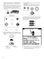
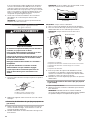
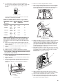
4. Remove cooktop burner caps and grates from parts
package. Burner caps should be level when properly
positioned. If burner caps are not properly positioned,
surface burners will not light. Place burner grates over
burners and caps.
A. Burner base
B. Burner cap
C. Burner grates
A
B
C
D
E
FG
H
A
B
A
D
EB
C
A. Small
B. X-Large
C. Oval D. Medium
E. Large
Complete Connection
1. Check that the gas pressure regulator shut-off valve is in the
on position.
A. Gas pressure regulator shut-off valve
shown in the on position
A
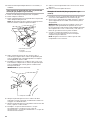
5. Align the gas tube opening in the burner base with the orifice
holder on the cooktop and the igniter electrode with the
notch in the burner base.
A. Burner cap
B. Gas tube opening
C. Burner base
D. Igniter electrode
E. Orifice holder
A
B
C
D
E
C
A
B

10
7. Plug into a grounded 3 prong outlet.
8. Slide range into final location, making sure the rear leveling
leg slides into the slot of the anti-tip bracket.
Electrical Shock Hazard
Plug into a grounded 3 prong outlet.
Do not remove ground prong.
Do not use an adapter.
Do not use an extension cord.
Failure to follow these instructions can result in death,
fire, or electrical shock.
WARNING
6. Place the burner caps on the appropriate burner bases.
IMPORTANT: The bottom of the small and medium caps are
different. Do not put the wrong size burner cap on the burner
base.
Small cap Medium cap
Wok cap
X-Large cap
Burner caps should be level when properly positioned. If burner
caps are not properly positioned, surface burners will not
light. The burner cap should not rock or wobble when properly
aligned.
A. Incorrect
B. Correct
A
B
AUX
SR
UR
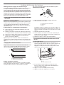
Install Griddle
1. Place the "FRONT" end of the griddle down, facing the oven
door. Verify that the lugs are placed onto the grate.
A. Front
B. Lugs
A
B
2. Clean the griddle before using. Refer to the Use and Care
Guide for cleaning instructions. The griddle can be placed
over the left, right, or center burner.

11
Verify Anti-Tip Bracket Is Installed
and Engaged
On Ranges with a Storage Drawer:
1. Remove the storage drawer. See the “Storage Drawer”
section.
2. Use a flashlight to look underneath the bottom of the range.
3. Visually check that the rear range foot is inserted into the slot
of the anti-tip bracket.
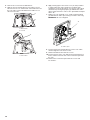
On Ranges with a Warming Drawer or Premium Storage
Drawer:
1. Place the outside of your foot against the bottom front of the
warming drawer or premium storage drawer, and grasp the
lower right or left side of the control panel as shown.
NOTE: If your countertop is mounted with a backsplash, it
may be necessary to grasp the range higher than is shown in
the illustration.
2. Slowly attempt to tilt the range forward.
If you encounter immediate resistance, the range foot is
engaged in the anti-tip bracket.
3. If the rear of the range lifts more than 1/2" (12.7 mm) off the
floor without resistance, stop tilting the range and lower it
gently back to the floor. The range foot is not engaged in the
anti-tip bracket.
IMPORTANT: If there is a snapping or popping sound when
lifting the range, the range may not be fully engaged in the
bracket. Check to see if there are obstructions keeping the range
from sliding to the wall or keeping the range foot from sliding
into the bracket. Verify that the bracket is held securely in place
by the mounting screws.
4. Slide the range forward, and verify that the anti-tip bracket is
securely attached to the floor or wall.
5. Slide range back so the rear range foot is inserted into the
slot of the anti-tip bracket.
IMPORTANT: If the back of the range is more than 2" (5.1 cm)
from the mounting wall, the rear range foot may not engage
the bracket. Slide the range forward and determine if there
is an obstruction between the range and the mounting wall.
Changes to the gas supply must be performed by a qualified
service technician. If you need assistance or service, refer to
the “Assistance or Service” section of the Use and Care Guide,
or the cover or “Warranty” section of the User Instructions, for
contact information.
6. Repeat steps 1 and 2 to ensure that the range foot is
engaged in the anti-tip bracket.
If the rear of the range lifts more than 1/2" (12.7 mm) off
the floor without resistance, the anti-tip bracket may not be
installed correctly. Do not operate the range without anti-
tip bracket installed and engaged. Please reference the
“Assistance or Service” section of the Use and Care Guide,
or the cover or “Warranty” section of the User Instructions,
to contact service.
Level Range
Determine if you have AquaLift
®
Technology or Steam Clean by
referring to the “Range Care” section of the User Instructions.
For Ranges with AquaLift
®
Technology or Steam Clean:
1. Place level on the oven bottom as indicated in one of the two
figures below depending on the size of the level. Check with
the level side to side and front to back.
2. If range is not level, pull range forward until rear leveling leg
is removed from the anti-tip bracket.
3. Follow the directions in Style 1 or Style 2, depending on the
style of drawer supplied with the range.
For Ranges without AquaLift
®
Technology or Steam Clean:
1. Place a standard flat rack in oven.
2. Place level on the rack and check levelness of the range, first
side to side; then front to back.
3. If range is not level, pull range forward until rear leveling leg
is removed from the anti-tip bracket.
4. Follow the directions in Style 1 or Style 2, depending on the
style of drawer supplied with the range.
Style 1: Ranges Equipped with a Storage Drawer:
Use a 1/4" (6.4 mm) drive ratchet, wrench or pliers to adjust
leveling legs up or down until the range is level. Push range
back into position. Check that rear leveling leg is engaged in
the anti-tip bracket.
Style 2: Ranges Equipped with a Warming Drawer or
Premium Storage Drawer:
Use a wrench or pliers to adjust leveling legs up or down
until the range is level. Push range back into position. Check
that rear leveling leg is engaged in the anti-tip bracket.
NOTE: Range must be level for satisfactory baking
performance and best cleaning results using AquaLift
®
Technology and Steam Clean functions.

12
Electronic Ignition System
Initial lighting and gas flame adjustments
Cooktop and oven burners use electronic igniters in place of
standing pilots. When the cooktop control knob is turned to the
“LITE” position, the system creates a spark to light the burner.
This sparking continues, as long as the control knob is turned to
“LITE.”
When the oven control is turned to the desired setting, sparking
occurs and ignites the gas.
Check Operation of Cooktop Burners
Standard Surface Burners
Push in and turn each control knob to the “LITE” position.
The flame should light within 4 seconds. The first time a burner
is lit, it may take longer than 4 seconds to light because of air in
the gas line.
If burners do not light properly:
■ Turn cooktop control knob to the “OFF” position.
■ Check that the range is plugged in. Check that the circuit
breaker has not tripped or the household fuse has not blown.
■ Check that the gas shut-off valves are set to the “open”
position.
■ Check that burner caps are properly positioned on burner
bases.
Repeat start-up. If a burner does not light at this point, turn
the control knobs to Off and contact your dealer or authorized
service company for assistance.
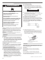
Adjust Flame Height
Adjust the height of top burner flames. The cooktop "low"
burner flame should be a steady blue flame approximately
1/4" (6.4 mm) high.
A. Low flame
B. High flame
To adjust standard burner:
The flame can be adjusted using the adjustment screw in the
center of the valve stem. The valve stem is located directly
underneath the control knob.
If the “low” flame needs to be adjusted:
A. Control knob stem
B. Screwdriver
C. Pliers
1. Light one burner and turn to lowest setting.
2. Remove the control knob.
Hold the knob stem with a pair of pliers. Use a small
flatblade screwdriver to turn the screw located in the center
of the control knob stem until the flame is the proper size.
3. Replace the control knob.
4. Test the flame by turning the control from “LO” to “HI,”
checking the flame at each setting.
5. Repeat above steps for each burner.
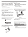
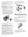
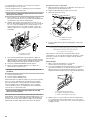
Check Operation of Oven Bake Burner
1. Remove the oven rack.
2. To remove the oven bottom: Remove two screws at the rear
of the oven bottom. Lift the rear of the oven bottom up and
back until the front of the panel is away from the front frame.
Remove from oven and place on a covered surface.
A. Screws
B. Oven bottom
3. You can check the burner flame by using a mirror.
Insert a mirror to one side of the burner. Look into the mirror
to check flame.
4. Push the BAKE keypad.
5. Push the START keypad.
The oven bake burner should light within 8 seconds. If
unsuccessful, the oven bake burner will pause for 40 seconds
then retry to light for another 8 seconds. It will try for 3 entire
cycles.
Electronic igniters are used to light the bake and broil burners.
Refer to the Use and Care Guide or User Instructions for proper
operation of the oven controls.
Adjust Oven Bake Burner Flame (if needed)
1. On models with a warming drawer, remove access cover
plate (1 screw) located at the back of the warming drawer
compartment.
2. Check the oven bake burner for proper flame.
This flame should have a 1/2" (12.7 mm) long inner cone of
bluish-green, with an outer mantle of dark blue, and should
be clean and soft in character. No yellow tips, blowing or
lifting of flame should occur.
A
B
A
B
C
A
B

13
3. If the oven bake flame needs to be adjusted, locate the
air shutter near the center rear of the range. Loosen the
locking screw and rotate the air shutter until the proper flame
appears. Tighten locking screw.
A. Locking screw
B. Air shutter
4. Push CANCEL/OFF when finished.
5. Reinstall flame spreader and oven bake burner cover.
Check Operation of Oven Broil Burner
1. Close the oven door.
2. Press the BROIL keypad.
3. Press the START keypad.
The oven burner should light within 8 seconds. If unsuccessful,
the oven bake burner will pause for 40 seconds then retry to
light for another 8 seconds. It will try for 3 entire cycles.
Refer to the Use and Care Guide or User Instructions for proper
operation of the oven controls.
Adjust Oven Broil Burner Flame (if needed)
Look through oven window to check broil burner for proper
flame. This flame should have a 1/2" (12.7 mm) long inner cone
of bluish-green, with an outer mantle of dark blue, and should be
clean and soft in character. No yellow tips, blowing or lifting of
flame should be present.
If flame needs to be adjusted:
1. Loosen the lock screw on the air shutter located at the rear
of the broil burner.
2. Adjust the air shutter as needed.
3. Tighten lock screw.
A. Lock screw
B. Air shutter
4. Press CANCEL/OFF when finished.
Warming Drawer or Premium Storage
Drawer
(on some models)
Remove all items from inside the warming drawer or premium
storage drawer, and allow the range to cool completely before
attempting to remove the drawer.
To Remove:
1. Open the warming drawer or premium storage drawer to its
fully open position.
2. Using a flat-blade screwdriver, gently loosen the warming
drawer or premium storage drawer from the glide alignment
notch and lift up the drawer alignment tab from the glide.
A. Flat-blade screwdriver
B. Drawer alignment tab
C. Drawer glide notch
3. Repeat Step 2 on the other side. The warming drawer or
premium storage drawer is no longer attached to the drawer
glides. Using both hands, pick up the warming drawer or
premium storage drawer to complete the removal.
To Replace:
1. Align the forward drawer notches with the notches in the
drawer glides on both sides. Place the rear alignment tabs
into the drawer glides on both sides.
A. Drawer alignment tab
B. Drawer glide notch
2. Push the warming drawer or premium storage drawer in all
the way.
3. Gently open and close the warming drawer or premium
storage drawer to ensure it is seated properly on the glides
on both sides.
A
B
A
B
A
B
C
A
B

14
Oven Door
For normal range use, it is not suggested to remove the oven
door. However, if removal is necessary, make sure the oven is
off and cool. Then, follow these instructions. The oven door is
heavy.
To Remove:
1. Open oven door all the way.
2. Pinch the hinge latch between two fingers and pull forward.
Repeat on other side of oven door.
A. Hinge latch
3. Close the oven door as far as it will shut.
4. Lift the oven door while holding both sides.
Continue to push the oven door closed and pull it away from
the oven door frame.
To Replace:
1. Insert both hanger arms into the door.
2. Open the oven door.
You should hear a click as the door is set into place.
3. Move the hinge levers back to the locked position. Check
that the door is free to open and close. If it is not, repeat the
removal and installation procedures.
Complete Installation
1. Check that all parts are now installed. If there is an extra
part, go back through the steps to see which step was
skipped.
2. Check that you have all of your tools.
3. Dispose of/recycle all packaging materials.
4. Check that the range is level. See the “Level Range” section.
5. Use a mild solution of liquid household cleaner and warm
water to remove waxy residue caused by shipping material.
Dry thoroughly with a soft cloth. For more information, see
the “Range Care” section of the Use and Care Guide or User
Instructions.
6. Read the Use and Care Guide or User Instructions.
7. Turn on surface burners and oven. See the Use and Care
Guide or User Instructions for specific instruction on range
operation.
If range does not operate, check the following:
■ Household fuse is intact and tight, or circuit breaker has not
tripped.
■ Range is plugged into a grounded 3 prong outlet.
■ Electrical supply is connected.
■ See “Troubleshooting” in the Use and Care Guide or User
Instructions.
8. When the range has been on for 5 minutes, check for heat.
If the range is cold, turn off the range and check that the gas
supply line shut-off valve is open.
■ If the gas supply line shut-off valve is closed, open it,
then repeat the 5-minute test as outlined above.
■ If the gas supply line shut-off valve is open, press
CANCEL on the oven control panel and contact a
qualified technician.
If you need Assistance or Service:
Please reference the “Assistance or Service” section of the Use
and Care Guide or the cover of the User Instructions, or contact
the dealer from whom you purchased your range.
A

15
GAS CONVERSIONS
Gas conversions from Natural gas to propane gas or from
propane gas to Natural gas must be done by a qualified installer.
Propane Gas Conversion
1. Turn the manual shut-off valve to the closed position.
A. To range
B. Manual shut-off valve closed position
C. Gas supply line
2. Unplug range or disconnect power.
To Convert Gas Pressure Regulator (Natural Gas to
Propane Gas)
1. Remove storage drawer or warming drawer. See the
“Storage Drawer” or “Warming Drawer or Premium Storage
Drawer” section.
2. Locate gas pressure regulator at rear of storage or warming
drawer compartment.
NOTE: On models with a warming drawer, an access cover
must be removed to access the gas pressure regulator.
A. Gas pressure regulator
IMPORTANT: Do not remove the gas pressure regulator.
WARNING
Explosion Hazard
Use a new CSA International approved gas supply line.
Install a shut-off valve.
Securely tighten all gas connections.
If connected to propane, have a qualified person make
sure gas pressure does not exceed 14" (36 cm) water
column.
Examples of a qualified person include:
licensed heating personnel,
authorized gas company personnel, and
authorized service personnel.
Failure to do so can result in death, explosion, or fire.
WARNING
Tip Over Hazard
A child or adult can tip the range and be killed.
Install anti-tip bracket to floor or wall per installation
instructions.
Slide range back so rear range foot is engaged in the
slot of the anti-tip bracket.
Re-engage anti-tip bracket if range is moved.
Do not operate range without anti-tip bracket installed
and engaged.
Failure to follow these instructions can result in death
or serious burns to children and adults.
A
B
C
A

16
3. Remove plastic cover from gas pressure regulator cap.
4. Turn gas pressure regulator cap counterclockwise with a
5/8" (15.9 mm) combination wrench to remove.
NOTE: Do not remove the spring beneath the cap.
A. Plastic cover
B. Gas pressure regulator cap with solid end facing out
C. Gas pressure regulator cap with hollow end facing out
D. Washer
E. Gas pressure regulator cap
5. Turn over the gas pressure regulator cap and reinstall on
regulator so that the hollow end faces out and the marking
“LP” is facing the direction shown in the above drawing.
6. Replace plastic cover over gas pressure regulator cap.
To Convert Surface Burners (Natural Gas to Propane
Gas)
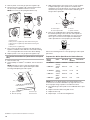
1. Remove burner cap.
2. Using a Phillips or Quadrex
®
screwdriver, remove the burner
base.
NOTE: Reinstall one of the screws through the range
cooktop to hold the orifice spud holder in place while
removing and replacing the orifice spuds.
A. Igniter electrode
B. Gas tube opening
C. Burner cap
D. Burner base
3. Apply masking tape to the end of a 9/32" (7 mm) nut driver
to help hold the gas orifice spud in the nut driver while
changing it. Press nut driver down onto the gas orifice spud
and remove by turning it counterclockwise and lifting out.
Set gas orifice spud aside.
A. Orifice spud
B. Orifice spud holder
C. Screw
D. Spark electrode
4. Remove the cardboard orifice spud holder shipped in
the literature package in the oven. Gas orifice spuds are
stamped with a number, marked with one color dot, and
have a groove in the hex area. Replace the Natural gas
orifice spud with the correct propane gas orifice spud.
A. Propane groove
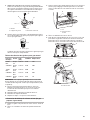
Refer to the following chart for correct propane gas orifice spud
placement.
Propane Gas Orifice Spud Chart for Surface Burners
Burner
Rating
Color Size (mm) ID
Number
Placement
14,200 BTU Yellow/
Orange
1.16 mm L116 LF
8,000 BTU Yellow/
Black
0.88 mm L88 LR
14,200 BTU Yellow/
Orange
1.16 mm L116 RF
5,000 BTU Yellow/
White
0.70 mm L70 RR
8,000 BTU Yellow/
Black
0.88 mm L88 CTR
NOTE: Refer to the Model Number and Serial Number Plate
located on the oven frame behind the top right side of the oven
door for proper sizing of spuds for each burner location.
5. Place Natural gas orifice spuds in the cardboard orifice spud
holder.
6. Replace the burner base using both screw.
7. Replace burner cap.
8. Repeat steps 1-7 for the remaining burners.
A
B
C
D
Side view before
Side view after
E
NG
LP
NG
LP
A
B
A
C
D
A
B
C
D
QUADREX is a registered trademark of Quadrex Consulting Inc.

17
To Convert Oven Bake Burner (Natural Gas to
Propane Gas)
1. Remove the oven racks and the oven door. See the “Oven
Door” section.
2. Remove two screws and washers at the rear of the oven
bottom.
3. Lift the rear of the oven bottom up and back until the front of
the panel is away from the front frame. Remove from oven
and set it aside on a covered surface.
A. Screws
B. Oven bottom
A
B
7. Replace the “47” spud with a “56” spud. Install the Propane
gas bake burner orifice spud, turning it clockwise until snug.
IMPORTANT: Do not overtighten.
8. Position the back of the bake burner over the oven orifice,
and then align the holes for the screws.
9. Reattach the bake burner with two screws.
10. Position the front of the oven bottom panel toward the front
frame, and then lower the rear of the oven bottom panel into
the oven.
11. Reattach the oven bottom panel with two screws and
two washers.
To Convert Oven Broil Burner (Natural Gas to
Propane Gas)
1. Remove the screw from the broil burner.
2. Remove the flame spreader.
3. Remove the broil burner from the broil burner orifice hood.
NOTE: The broil burner will hang in the back of the oven
while changing the orifice hood.
A. Broil burner
B. Screws
C. Orifice hood
4. Use a 3/8" (9.5 mm) combination wrench and turn the
Natural gas broil burner orifice hood counterclockwise to
remove. The hood will be stamped with a “155.”
A. Orifice spud
A
4. Remove two screws from the bake burner.
5. Slide the front of the bake burner to the side to remove
tab from front of oven. Lift the back of the bake burner off
the oven orifice, and set the bake burner aside. Do not
disconnect the wire.
A. Bake burner
B. Screws
A. Oven orifice
6. Apply masking tape to the end of a 3/8" (9.5 mm) nut driver
to help hold the gas orifice spud in the nut driver while
changing it. Press nut driver down onto the gas orifice spud
and remove by turning the Natural gas bake burner orifice
spud counterclockwise to remove. The spud will be stamped
with a “47.”
A
A
B
A
B
C

18
5. Replace the “155” hood with a “100” hood. Install the
propane gas broiler burner orifice hood, turning it clockwise
until snug.
IMPORTANT: Do not overtighten.
6. Place the broil burner on the broil burner orifice hood and
insert the broil burner ceramic igniter in the hole in the rear of
the oven.
7. Position the broil burner against the top of the oven and
attach it with two screws.
8. Replace storage drawer or warming drawer. See the
“Storage Drawer” or “Warming Drawer or Premium Storage
Drawer” section.
9. Replace the oven door if it has been removed. See the “Oven
Door” section.
10. Replace the oven racks.
Complete Installation (Natural Gas to Propane Gas)
1. Refer to the “Make Gas Connection” section for properly
connecting the range to the gas supply.
2. Refer to the “Electronic Ignition System” section for proper
burner ignition, operation, and burner flame adjustments.
IMPORTANT: You may have to adjust the “LO” setting for
each cooktop burner.
Checking for proper cooktop, bake and broil burner flame
is very important. The small inner cone should have a very
distinct blue flame 1/4" (6.4 mm) to 1/2" (13 mm) long. The
outer cone is not as distinct as the inner cone. Propane gas
flames have a slightly yellow tip.
3. Refer to “Complete Installation” in the “Installation
Instructions” section of these instructions to complete this
procedure.
NOTE: Make sure to save the orifices that have just been
replaced in the conversion.
Natural Gas Conversion
1. Turn the manual shut-off valve to the closed position.
A. To range
B. Manual shut-off valve closed position
C. Gas supply line
2. Unplug range or disconnect power.
To Convert Gas Pressure Regulator (Propane Gas to
Natural Gas)
1. Remove storage drawer or warming drawer. See the
“Storage Drawer” or “Warming Drawer or Premium Storage
Drawer” section.
2. Locate gas pressure regulator at rear of storage or warming
drawer compartment.
NOTE: On models with a warming drawer, an access cover
must be removed to access the gas pressure regulator.
A. Gas pressure regulator
IMPORTANT: Do not remove the gas pressure regulator.
x.xx
A
WARNING
Tip Over Hazard
A child or adult can tip the range and be killed.
Install anti-tip bracket to floor or wall per installation
instructions.
Slide range back so rear range foot is engaged in the
slot of the anti-tip bracket.
Re-engage anti-tip bracket if range is moved.
Do not operate range without anti-tip bracket installed
and engaged.
Failure to follow these instructions can result in death
or serious burns to children and adults.
A
B
C
A

19
3. Remove plastic cover from gas pressure regulator cap.
4. Turn gas pressure regulator cap counterclockwise with a
5/8" (15.9 mm) combination wrench to remove.
NOTE: Do not remove the spring beneath the cap.
A. Plastic cover
B. Gas pressure regulator cap with hollow end facing out
C. Gas pressure regulator cap with solid end facing out
D. Washer
E. Gas pressure regulator cap
5. Turn over the gas pressure regulator cap and reinstall on
regulator so that the solid end faces out and the marking
“NG” is facing the direction shown in the above drawing.
6. Replace plastic cover over gas pressure regulator cap.
To Convert Surface Burners (Propane Gas to Natural
Gas)
1. Remove burner cap.
2. Using a Phillips or Quadrex
®
screwdriver, remove the burner
base.
NOTE: Reinstall one of the screws through the range
cooktop to hold the orifice spud holder in place while
removing and replacing the orifice spuds.
3. Apply masking tape to the end of a 9/32" (7 mm) nut driver
to help hold the gas orifice spud in the nut driver while
changing it. Press nut driver down onto the gas orifice spud
and remove by turning it counterclockwise and lifting out.
Set gas orifice spud aside.
A. Orifice spud
B. Orifice spud holder
C. Screw
D. Spark electrode
4. Gas orifice spuds are stamped with a number on the side.
Replace the propane gas orifice spud with the correct
Natural gas orifice spud.
A. Stamped number
Burner
Rating
Color Size (mm) ID
Number
Placement
18,000 BTU Red/
Black
2.00 mm N216 LF
9,500 BTU Red/
White
1.40 mm N210 LR
15,000 BTU Red/
Yellow
1.80 mm N200 RF
5,000 BTU Blue/
White
1.04 mm N190 RR
8,000 BTU Red/
White
1.40 mm N185 CTR
Refer to the following chart for the correct Natural gas orifice
spud placement.
Natural Gas Orifice Spud Chart
NOTE: Refer to the Model Number and Serial Number Plate
located on the oven frame behind the top right side of the oven
door for proper sizing of spuds for each burner location.
5. Place propane gas orifice spuds in plastic parts bag for
future use and keep with package containing literature.
6. Replace the burner base using both screws.
7. Replace burner cap.
8. Repeat steps 1-7 for the remaining burners.
To Convert Oven Bake Burner (Propane Gas to
Natural Gas)
1. Remove the oven racks and the oven door. See the “Oven
Door” section.
2. Remove two screws and washers at the rear of the oven
bottom.
3. Lift the rear of the oven bottom up and back until the front of
the panel is away from the front frame. Remove from oven
and set it aside on a covered surface.
A. Screws
B. Oven bottom
A
B
A
B
C
D
Side view before
Side view after
E
NG
LP
LP
NG
B
A
C
D
XXX
A

20
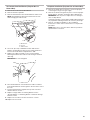
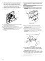
4. Remove two screws from the bake burner.
5. Slide the front of the bake burner to the side to remove
tab from front of oven. Lift the back of the bake burner off
the oven orifice, and set the bake burner aside. Do not
disconnect the wire.
A. Bake burner
B. Screws
A. Oven orifice
6. Apply masking tape to the end of a 3/8" (9.5 mm) nut driver
to help hold the gas orifice spud in the nut driver while
changing it. Press nut driver down onto the gas orifice spud
and remove by turning the propane gas bake burner orifice
spud counterclockwise to remove. The spud will be stamped
with a “56.”
7. Replace the “56” spud with a “47” spud. Install the Natural
gas bake burner orifice spud, turning it clockwise until snug.
IMPORTANT: Do not overtighten.
A. Orifice spud
8. Position the back of the bake burner over the oven orifice,
and then align the holes for the screws.
9. Reattach the bake burner with two screws.
10. Position the front of the oven bottom panel toward the front
frame, and then lower the rear of the oven bottom panel into
the oven.
11. Reattach the oven bottom panel with two screws and
two washers.
A
A
B
A
La page est en cours de chargement...
La page est en cours de chargement...
La page est en cours de chargement...
La page est en cours de chargement...
La page est en cours de chargement...
La page est en cours de chargement...
La page est en cours de chargement...
La page est en cours de chargement...
La page est en cours de chargement...
La page est en cours de chargement...
La page est en cours de chargement...
La page est en cours de chargement...
La page est en cours de chargement...
La page est en cours de chargement...
La page est en cours de chargement...
La page est en cours de chargement...
La page est en cours de chargement...
La page est en cours de chargement...
La page est en cours de chargement...
La page est en cours de chargement...
La page est en cours de chargement...
La page est en cours de chargement...
La page est en cours de chargement...
La page est en cours de chargement...
La page est en cours de chargement...
La page est en cours de chargement...
La page est en cours de chargement...
La page est en cours de chargement...
La page est en cours de chargement...
La page est en cours de chargement...
La page est en cours de chargement...
La page est en cours de chargement...
La page est en cours de chargement...
La page est en cours de chargement...
La page est en cours de chargement...
La page est en cours de chargement...
La page est en cours de chargement...
La page est en cours de chargement...
La page est en cours de chargement...
La page est en cours de chargement...
La page est en cours de chargement...
La page est en cours de chargement...
La page est en cours de chargement...
La page est en cours de chargement...
La page est en cours de chargement...
La page est en cours de chargement...
La page est en cours de chargement...
La page est en cours de chargement...
La page est en cours de chargement...
La page est en cours de chargement...
La page est en cours de chargement...
La page est en cours de chargement...
-
 1
1
-
 2
2
-
 3
3
-
 4
4
-
 5
5
-
 6
6
-
 7
7
-
 8
8
-
 9
9
-
 10
10
-
 11
11
-
 12
12
-
 13
13
-
 14
14
-
 15
15
-
 16
16
-
 17
17
-
 18
18
-
 19
19
-
 20
20
-
 21
21
-
 22
22
-
 23
23
-
 24
24
-
 25
25
-
 26
26
-
 27
27
-
 28
28
-
 29
29
-
 30
30
-
 31
31
-
 32
32
-
 33
33
-
 34
34
-
 35
35
-
 36
36
-
 37
37
-
 38
38
-
 39
39
-
 40
40
-
 41
41
-
 42
42
-
 43
43
-
 44
44
-
 45
45
-
 46
46
-
 47
47
-
 48
48
-
 49
49
-
 50
50
-
 51
51
-
 52
52
-
 53
53
-
 54
54
-
 55
55
-
 56
56
-
 57
57
-
 58
58
-
 59
59
-
 60
60
-
 61
61
-
 62
62
-
 63
63
-
 64
64
-
 65
65
-
 66
66
-
 67
67
-
 68
68
-
 69
69
-
 70
70
-
 71
71
-
 72
72


Whirlpool WFG775H0HB Guide d'installation
- Catégorie
- Cuisinières
- Taper
- Guide d'installation
