
01
EN
A5 V18.2
USER MANUAL
KULLANIM KILAVUZU
MANUAL DE USUARIO
MANUEL DE L’UTILISATEUR
MANUALE UTENTE
BENUTZERHANDBUCH

EN
A5 V18.2
USER
MANUAL
TABLE OF CONTENT
CHAPTER 1 - Preface ...................................................... 02
1.1 Regulations Information ..................................................02
FCC Information ........................................................................03
RF Exposure Information(SAR) .............................................04
1.2 Safety Information ............................................................05
1.3 Conventions For This Manual ..........................................05
CHAPTER 2 - Getting To Know The Basics ..................... 06
2.1 Product Specifcation ........................................................06
2.2 Preparing your Computer ................................................08
2.3 Product Overview ...............................................................09
CHAPTER 3 - Getting Started ......................................... 14
3.1 AC Adapter ...........................................................................14
3.2 Knowing The Keyboard .....................................................15
3.2.1 For Keyboard Users ........................................................15
3.3 Using the touchpad / clickpad ........................................17
CHAPTER 4 - Bios Setup ................................................. 18
4.1 About Bios Setup ...............................................................18
4.1.1 When To Use Bios Setup? ............................................18
4.1.2 How to Run BIOS Setup? ..............................................18
4.2 BIOS Setup Menu ...............................................................18
4.2.1 Main Menu ........................................................................19
4.2.2 Advanced Menu ...............................................................20
4.2.3 Security Menu .................................................................20
4.2.4 Boot Menu ........................................................................22
4.2.5 Exit Menu ..........................................................................22

02
EN
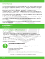
The information in this user’s manual is protected by copyright laws, all parts of
this manual, including the products and software described in it, can not be
reproduced, transmitted, transcribed, stored in a retrieval system, nor
translated into any language.
THE MANUFACTURER OR RESELLER SHALL NOT BE LIABLE FOR ERRORS OR
OMISSIONS CONTAINED IN THIS MANUAL AND SHALL NOT BE LIABLE FOR ANY
CONSEQUENTIAL DAMAGES, WHICH MAY RESULT FROM THE PERFORMANCE OR
USE OF THIS MANUAL.
The illustrations in this user’s manual are for reference only. Actual product
specifcations may vary with territories. The information in this user’s manual is
subject to change without notice.
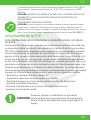
CHAPTER 1
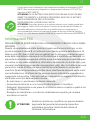
1.1 Regulations Information
NOTICE
Preface
• CE compliance
This device is classed as a technical information equipment (ITE) in class B
and is intended for use in living room and ofce. The CE-mark approves the
conformity by the EU-guidelines:
- EMC Directive 2014/30/EU,
- Low Voltage Directive 2014/35/EU(equals A2 : 2013),
- RF Directive 2014/53/EU
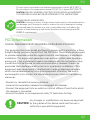
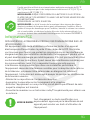
Rechargeable Battery Notice Do not
1. Throw into fire or a hot oven, or mechanically crush or cutting of a
BATTERY
2. Throw or immerse into water
3. Heat to more than 60°C
4. Repaire or disassemble
5. Leave in an extremely low air pressure environment
6. Leave in an extremely high-temperature environment A power cord
is connected to a socket-outlet with earthing connection.

03
EN
The unit can be operated at an ambient temperature of max. 35°C (95°F).
Do not subject it to temperatures below 5°C (41°F) or above 40°C (104 °F).
CAUTION: RISK OF EXPLOSION IF BATTERY IS REPLACED BY AN INCORRECT
TYPE DISPOSE OF USED BATTERIES ACCORDING TO THE INSTRUCTIONS.
PREVENTION OF HEARING LOSS
CAUTION: Listening to music at high volume levels and for extended durations
can damage one’s hearing. In order to reduce the risk of damage to hearing,
one should lower the volume to a safe, comfortable level, and reduce the
amount of time listening at high levels. Headsets should comply with EN
50332-2 requirements.
FCC Information
FEDERAL COMMUNICATIONS COMMISSION INTERFERENCE STATEMENT
This equipment has been tested and found to comply with the limits for a Class
B digital device, pursuant to part 15 of the FCC Rules. These limits are designed
to provide reasonable protection against harmful interference in a residential
installation. This equipment generates, uses and can radiate radio frequency
energy and, if not installed and used in accordance with the instructions, may
cause harmful interference to radio communications. However, there is no
guarantee that interference will not occur in a particular installation. If this
equipment does cause harmful interference to radio or television reception,
which can be determined by turning the equipment off and on, the user is
encouraged to try to correct the interference by one or more of the following
measures:
-Reorient or relocate the receiving antenna.
-Increase the separation between the equipment and receiver.
-Connect the equipment into an outlet on a circuit different from that to which
the receiver is connected.
-Consult the dealer or an experienced radio/ TV technician for help.
Any changes or modifications not expressly approved
by the grantee of this device could void the user’s
authority to operate the equipment.
CAUTION:

04
EN
RF Exposure Information (SAR)
This device meets the government’s requirements for exposure to
radio waves. This device is designed and manufactured not to exceed
the emission limits for exposure to radio frequency (RF) energy set by
the Federal Communications Commission of the U.S. Government.
The exposure standard employs a unit of measurement known as the
Specific Absorption Rate, or SAR. The SAR limit set by the FCC is 1.6
W/kg. Tests for SAR are conducted using standard operating positions
accepted by the FCC with the EUT transmitting at the specified power
level in different channels.
The FCC has granted an Equipment Authorization for this device with
all reported SAR levels evaluated as in compliance with the FCC RF
exposure guidelines. SAR information on this device is on file with the
FCC and can be found under the Display Grant section of www.fcc.gov/
eot/ea/fccid after searching on FCC ID: 2AKHFAX201NG .
This device complies with Part 15 of the FCC Rules. Operation is
subject to the following two conditions:
(1) this device may not cause harmful interference, and
(2) this device must accept any interference received, including
interference that may cause undesired operation.
Any changes or modifications not expressly approved
by the grantee of this device could void the user’s
authority to operate the equipment.
CAUTION:

05
EN
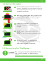
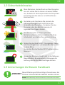
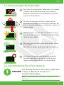
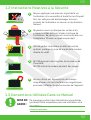
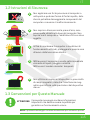
1.2 Safety Information
Do not apply heavy pressure to the computer or
subject it to any form of strong impact as this can
damage the computer’s components or otherwise
cause it to malfunction.
1
Never cover or block the air vents including those
located at the base of the computer. Never cover
your computer or AC adaptor with any object.
2
Do NOT expose to or use near liquid, rain, or
moisture.
Do NOT use the modem during electrical storms.
4
Do not use or expose this device around
magnetic felds as magnetic interference may
affect the performance of the device.
5
To keep your computer in prime operating
condition, protect your work area from direct
sunlight.
3
1.3 Conventions For This Manual
This message contains important information
that must be followed for safe operation.
CAUTION:
NOTE: This message contains information for special situations.

06
EN
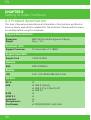
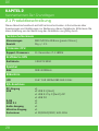
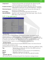
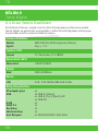
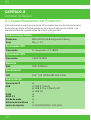
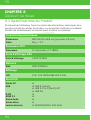
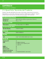
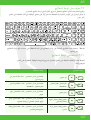
2.1 Product Specifcation
CHAPTER 2
Getting To Know The Basics
This User’s Manual provides technical information of instructions and illustra-
tions on how to operate this notebook for the customer. Please read this manu-
al carefully before using this notebook.
Physical Characteristic
Processor-CPU
Graphic Card-GPU
Memory
I/O Port
Display
360.2x243.5x19.9mm(panel=2.6mm)
2kg +/- 5%
11. Generation i7-11800H
4 GB RTX 3050
DDR4 3200MHz
15.6’’ FHD 1920x1080 16:9 144Hz
x1
x2 USB 3.1 (Gen1)
x1 USB 3.1 Tip C (Gen2)+DP
x1 USB 2.0
x1
x1
x1
x1
x1 SD/SDHC/SDXC, UHS-50hz
Dimension
Weight
Support Processor
Graphic Card
RAM
LCD
DC-In
USB
RJ45
HDMI 2.1
Audio Out
Microphone In
Card Reader

07
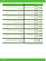
EN
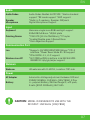
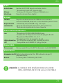
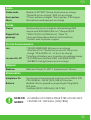
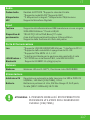
MODEL IS DESIGNED TO USE WITH THE
DC INPUT: 150 Watts (19V/7.89A)
CAUTION:
Input
Communication Port
Power
Webcam
Audio
Audio Codec Realtek ALC274CG *Azalia standard
support *D3 mode support *AMP support
*Build-in 2 speakers, Speaker: 2W/each
Digital Microphone Support
Memrane single zone RGB backlight support
340x109.2x3.6mm *US/UK plate
*TDA1470 (114.5x70x0.8mm) *TP mylar
*Enable/Disable area: 10mmx10mm
*Palm Rejection:Support
*Supports 10/100/1000/2500 Mb/sec *PCI-E
interface *Power Down Mode D1~D3 support
*PCIe ASPM L1.1, L1.2 support
*M.2 2230 w/CNVi interface, Intel WiFi6 AX201
IEEE802.11 a/b/g/n/ac/ax support
HD webcam with D-MICX1, Location: TOP side
Automatics Voltage adjustment between 100 and
240VAC 50/60Hz, 150 Watts (19V/7.89A), 3 Pins
Li- polymer Battery, SW Gas Gauge IC, soft pack,
3 cells (3S1P 4100mAh) 46.74 Wh
Audio Codec
Speaker
Microphone
Keyboard
Pointing Device
Lan
Wireless Lan+BT
Webcam
AC Adapter
Battery

08
EN
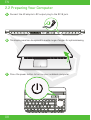
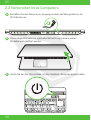
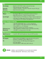
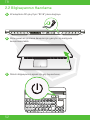
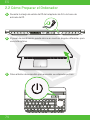
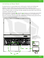
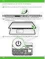
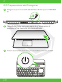
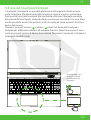
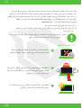
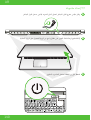
2.2 Preparing Your Computer
AConnect the AC adaptor’s DC output plug to the DC IN jack.
BThe display panel can be opened to a wide range of angles for optimalviewing.
CPress the power button to turn on your notebook computer.

09
EN
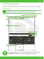
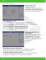
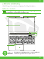
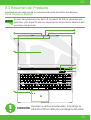
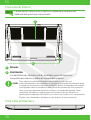
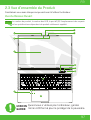
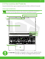
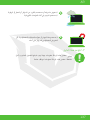
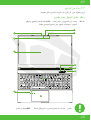
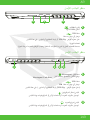
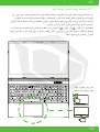
2.3 Product Overview
Please become familiar with each component before you operate the computer.
Top-Open View
The product’s color/ LED color, I/O port, indicator location, and
specification will depend upon the actually shipping product.
NOTE
When you are not using the computer, keep the
LCDscreen closed to protect it from dust.
CAUTION:
1
2
4
3
5
10
11
6
7
8
9

10
EN
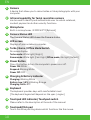
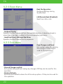
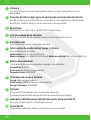
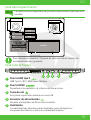
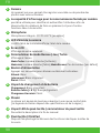
1Camera
A device that allows you to record video or take photographs with your
computer.
2Infrared capability for facial reconition camera
can be used to identify and authenticate user to unlock notebook,
conduct payment and other security functions.
3Microphone
Built-in microphones. IR CCD MIC*2(Optional)
4Camera Status LED
The Camera Status LED shows the Camera status.
6Turbo / Game / Office Mode Switch
On screen display.
Turbo mode: White light (Bright)
Game mode: White light (Faint light) Office mode : No light (Default )
7Power Button
Press this button to turn the computer’s power on or off.
Power ON: White
Suspend: Blinking White
Power Off: OFF
8
9
Charging & Battery indicator
Charging: Blinking White
Battery Low (<6%): Blinking Orange
Charging finish: OFF
10
11
Keyboard
The keyboard provides keys with comfortable travel
(The keyboard legend will depend on the spec / region)
Touchpad LED indicator/ Touchpad switch
Please refer to the description at the end of the manual
Touchpad/Click pad
Touch-sensitive pointing device which functions like the mouse.
5LCD screen
Displays of your notebook computer.

11
EN
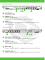
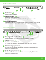
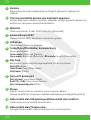
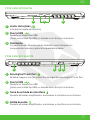
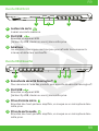
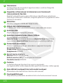
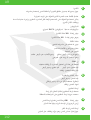
Left Side View
1Kensington® Lock Port
To be secured using Kensington® Lock Port security products.
2USB Ports
Connects an USB device.
(such as USB Zip drive, keyboard or mouse) into this jack.
3
4
Mic In Jack
Connects amplified speakers, headphones or microphone into this jack.
Audio Out Jack
Connects amplified speakers, headphones or microphone into this jack.
Right Side View
1Card Reader
Insert memory card.
2USB Ports
Connects an USB device
(such as USB Zip drive, keyboard or mouse) into this jack.
3Vents
The thermal vents are designed to cool the internal components and
avoid overheating.
1
1 2 3 4
2 3

12
EN
To reduce the possibility of heat-related injuries or of overheating the
computer, do not place the computer directly on your lap or obstruct
the computer air vents. Use the computer only on a hard, flat surface.
Do not allow another hard surface, such as an adjoining optional print-
er, or a soft surface, such as pillows or rugs or clothing, to block airflow.
Also, do not allow the AC adapter to come into contact with the skin or
a soft surface, such as pillows or rugs or clothing, during operation.
CAUTION:
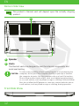
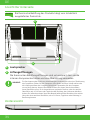
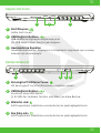
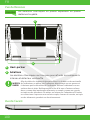
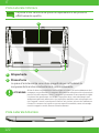
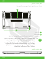
Bottom Side View
The product’s thermal vent will depend upon the actually shipping
product.
NOTE
1
Vents
The thermal vents are designed to cool the internal components and
avoid overheating.
2
Speaker
2
1
Front Side Vtiew

13
EN
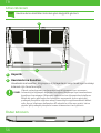
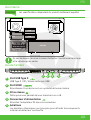
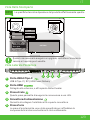
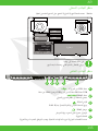
Compartment View
SSD
RAM
RAM
BATTERY (Option)
SSD(Option)
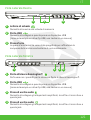
Back Side View
5
Power Connector
Connects the AC adapter into this connector.
1
Vents
The thermal vents are designed to cool the internal components and
avoid overheating.
2
3
HDMI Port
Connected to the screen, or home theater system.
4
USB Type C Port
USB Type C / DP / USB Power Delivery
Specification will depend upon the actually shipping product.
If need to upgrade. Please contact technical support and
after-sales service.
NOTE
HDD(Option)
Reserved space
1 2 3 4 5
Network Jack
This jack lets you connect to a LAN.

14
EN
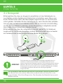
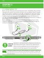
CHAPTER 3
Getting Started
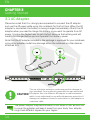
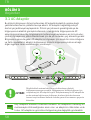
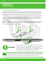
3.1 AC Adapter
Please be noted that it is strongly recommended to connect the AC adapter
and use the AC power while using this notebook for the frst time. When the AC
adapter is connected, the battery is being charged immediately. Attach the AC
adaptor when you need to charge the battery or you want to operate from AC
power. It is also the fastest way to get started, because the battery pack will
need to be charged before you can operate from battery power.
Note that the AC adapter included in the package is approved for your notebook;
using other adapter model may damage either the notebook or other devices
attached to it.
The power adapter may become warm to hot when in use. Be sure not
to cover the adapter and keep it away from your body. Your adapter
might look different depend on your region.
NOTE
The use of inferior extension cords may result in damage to
your notebook. Your notebook comes with its own authorized
AC adapter. Use of a different AC adapter or cable extension
which is not authorized for use will void warranty protection if
damage to hardware is found in association to said adapter or
extension cable.
CAUTION:
DC IN
1
2 3

15
EN
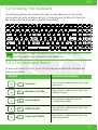
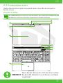
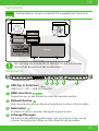
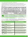
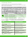
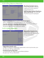
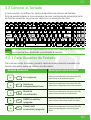
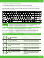
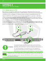
3.2 Knowing The Keyboard
3.2.1 For Keyboard Users
The following defnes the colored hot keys on the Keyboard. The colored
commands can only be accessed by frst pressing and holding the function
key while pressing a key with a colored command.
To activate these functions, press the hot key associated with the desired
function as below:
The number of keys available on your keyboard will depend on which
country/region your computer is confgured for.
NOTE
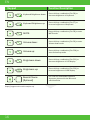
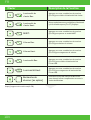
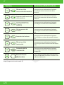
Suspend: Press this key combination (Fn+F1) to enter
sleep mode.
Press this key combination (Fn+F2) to turn
Windows Lock/On .
Press this key combination (Fn+F3)
to enable Display Mode.
Press this key combination (Fn+F4) to turn
all radios on or off.
Press this key combination (Fn+F5) to On/
Off Touch pad mode
Windows Lock/On:
Display Mode:
RADIO On/Off:
Touch pad On/Off:
Keypad Function Description

16
EN
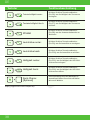
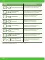
Keyboard Brightness down: Press this key combination (Fn+F6) to
decrease brightness of Keyboard.
Press this key combination (Fn+F7) to
increase brightness of Keyboard.
Press this key combination (Fn+F8) to enter
MUTE mode.
Press this key combination (Fn+F9) to enter
Volume down mode.
Press this key combination (Fn+F10) to
enter Volume up mode.
Press this key combination (Fn+F11) to
decrease brightness of LCD display.
Press this key combination (Fn+F12) to
increase brightness of LCD display.
Keyboard Brightness up:
MUTE:
Volume down:
Volume up:
Brightness down:
Brightness up:
Keypad Function Description
For a full list of Windows keyboard
shortcuts, please visit the Microsoft
official website
https://support.microsoft.com/en-us/
Search Charm:
(Optional)

17
EN
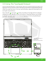
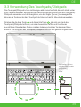
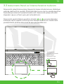
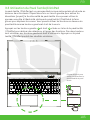
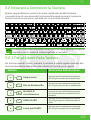
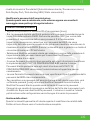
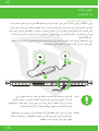
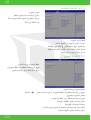
3.3 Using The Touchpad/Clickpad
The touchpad/clickpad is a rectangular electronic panel located just below your
keyboard. You can use the static-sensitive panel of the touchpad/clickpad and
slide it to move the cursor. You can use the buttons below the touchpad as left
and right mouse buttons.
Press the left and right buttons located on the edge of the touchpad/
clickpad to make selections and run functions. These two buttons are similar
to the left and right buttons on a mouse. Tapping on the touchpad/clickpad
produces similar results.
1 2
Click twice will open or
close (light)
touchpad functionality
1
1
2
2

18
EN
CHAPTER 4
Bios Setup
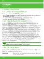
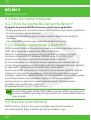
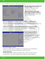
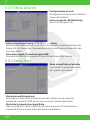
4.1 About Bios Setup
4.1.1 When To Use Bios Setup?
You may need to run the BIOS Setup when:
• An error message appears on the screen during the system booting up and is
requested to run SETUP.
• You want to change the default settings for customized features.
• You want to reload the default BIOS settings.
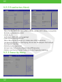
4.2 BIOS Setup Menu
4.1.2 How To Run BIOS Setup?
To run the BIOS Setup Utility, turn on the notebook and press the [Del] key
during the POST procedure.
If the message disappears before you respond and you still wish to enter Setup,
either restart the system by turning it OFF and ON, or simultaneously pressing
[Ctrl]+[Alt]+[Del] keys to restart.
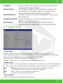
Be noted that the screen snaps and setting options in this chapter are for your
references only.The actual setting screens and options on your Notebook may
be different because of BIOS update.
The setup function only can be invoked by pressing [Del] or [F2] key during
POST that provide a approach to change some setting and confguration the
user prefer, and the changed values will save in the NVRAM and will take effect
after the system rebooted. The setup uses a menu interface to allow the user to
confgure their system and the features are briefly listed as follow.
Press [F7] key for Boot Menu.
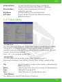
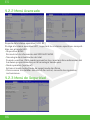
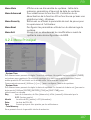
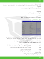
Once you enter the BIOS Setup Utility, the Main Menu will appear on the screen.
Select the tags to enter the other menus.
Main Menu Show system overview about memory size and setting of
system time and date.
The drivers, BIOS and utilities bundled in the support DVD may vary by
models and are subject to change without notice.
NOTE

19
EN
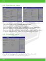
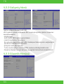
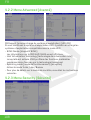
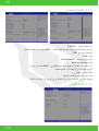
Advanced Menu To select the XD feature enable or disable XD
feature only work with Intel platform + Windows.
Security Menu Install or clear the password settings for
supervisor and user.
Boot Menu Confgure Settings during System Boot.
EXIT Menu Save or discard the changes before leaving the
BIOS Setup Menu.
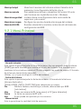
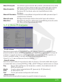
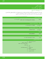
4.2.1 Main Menu
• System Time
This item allows you to set the system time. There is a small internal (CMOS)
battery which is designed to maintain your system clock. It is designed to
maintain time even when the PC is powered down or in sleep mode. The time
format is [hour:minute:second].
Use [+] or [-] to configure system Time.
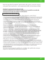
• System Date
This item allows you to set the system date. The date format is
[day:month:date:year]. Use [ENTER], [TAB] or [SHIFT-TAB] to select a field.
Day Day of the week, from Sun to Sat, which is determined by
BIOS (read-only).
Month (Month) The month from 01 (January) to 12 (December).
Date (Date)date from 01 to 31.
Year (Year) The year can be adjusted by users.
• Total Memory
This allows you to see the total amount of memory.
La page est en cours de chargement...
La page est en cours de chargement...
La page est en cours de chargement...
La page est en cours de chargement...
La page est en cours de chargement...
La page est en cours de chargement...
La page est en cours de chargement...
La page est en cours de chargement...
La page est en cours de chargement...
La page est en cours de chargement...
La page est en cours de chargement...
La page est en cours de chargement...
La page est en cours de chargement...
La page est en cours de chargement...
La page est en cours de chargement...
La page est en cours de chargement...
La page est en cours de chargement...
La page est en cours de chargement...
La page est en cours de chargement...
La page est en cours de chargement...
La page est en cours de chargement...
La page est en cours de chargement...
La page est en cours de chargement...
La page est en cours de chargement...
La page est en cours de chargement...
La page est en cours de chargement...
La page est en cours de chargement...
La page est en cours de chargement...
La page est en cours de chargement...
La page est en cours de chargement...
La page est en cours de chargement...
La page est en cours de chargement...
La page est en cours de chargement...
La page est en cours de chargement...
La page est en cours de chargement...
La page est en cours de chargement...
La page est en cours de chargement...
La page est en cours de chargement...
La page est en cours de chargement...
La page est en cours de chargement...
La page est en cours de chargement...
La page est en cours de chargement...
La page est en cours de chargement...
La page est en cours de chargement...
La page est en cours de chargement...
La page est en cours de chargement...
La page est en cours de chargement...
La page est en cours de chargement...
La page est en cours de chargement...
La page est en cours de chargement...
La page est en cours de chargement...
La page est en cours de chargement...
La page est en cours de chargement...
La page est en cours de chargement...
La page est en cours de chargement...
La page est en cours de chargement...
La page est en cours de chargement...
La page est en cours de chargement...
La page est en cours de chargement...
La page est en cours de chargement...
La page est en cours de chargement...
La page est en cours de chargement...
La page est en cours de chargement...
La page est en cours de chargement...
La page est en cours de chargement...
La page est en cours de chargement...
La page est en cours de chargement...
La page est en cours de chargement...
La page est en cours de chargement...
La page est en cours de chargement...
La page est en cours de chargement...
La page est en cours de chargement...
La page est en cours de chargement...
La page est en cours de chargement...
La page est en cours de chargement...
La page est en cours de chargement...
La page est en cours de chargement...
La page est en cours de chargement...
La page est en cours de chargement...
La page est en cours de chargement...
La page est en cours de chargement...
La page est en cours de chargement...
La page est en cours de chargement...
La page est en cours de chargement...
La page est en cours de chargement...
La page est en cours de chargement...
La page est en cours de chargement...
La page est en cours de chargement...
La page est en cours de chargement...
La page est en cours de chargement...
La page est en cours de chargement...
La page est en cours de chargement...
La page est en cours de chargement...
La page est en cours de chargement...
La page est en cours de chargement...
La page est en cours de chargement...
La page est en cours de chargement...
La page est en cours de chargement...
La page est en cours de chargement...
La page est en cours de chargement...
La page est en cours de chargement...
La page est en cours de chargement...
La page est en cours de chargement...
La page est en cours de chargement...
La page est en cours de chargement...
La page est en cours de chargement...
La page est en cours de chargement...
La page est en cours de chargement...
La page est en cours de chargement...
La page est en cours de chargement...
La page est en cours de chargement...
La page est en cours de chargement...
La page est en cours de chargement...
La page est en cours de chargement...
La page est en cours de chargement...
La page est en cours de chargement...
La page est en cours de chargement...
La page est en cours de chargement...
La page est en cours de chargement...
La page est en cours de chargement...
La page est en cours de chargement...
La page est en cours de chargement...
La page est en cours de chargement...
La page est en cours de chargement...
La page est en cours de chargement...
La page est en cours de chargement...
La page est en cours de chargement...
La page est en cours de chargement...
La page est en cours de chargement...
La page est en cours de chargement...
La page est en cours de chargement...
La page est en cours de chargement...
La page est en cours de chargement...
La page est en cours de chargement...
La page est en cours de chargement...
La page est en cours de chargement...
-
 1
1
-
 2
2
-
 3
3
-
 4
4
-
 5
5
-
 6
6
-
 7
7
-
 8
8
-
 9
9
-
 10
10
-
 11
11
-
 12
12
-
 13
13
-
 14
14
-
 15
15
-
 16
16
-
 17
17
-
 18
18
-
 19
19
-
 20
20
-
 21
21
-
 22
22
-
 23
23
-
 24
24
-
 25
25
-
 26
26
-
 27
27
-
 28
28
-
 29
29
-
 30
30
-
 31
31
-
 32
32
-
 33
33
-
 34
34
-
 35
35
-
 36
36
-
 37
37
-
 38
38
-
 39
39
-
 40
40
-
 41
41
-
 42
42
-
 43
43
-
 44
44
-
 45
45
-
 46
46
-
 47
47
-
 48
48
-
 49
49
-
 50
50
-
 51
51
-
 52
52
-
 53
53
-
 54
54
-
 55
55
-
 56
56
-
 57
57
-
 58
58
-
 59
59
-
 60
60
-
 61
61
-
 62
62
-
 63
63
-
 64
64
-
 65
65
-
 66
66
-
 67
67
-
 68
68
-
 69
69
-
 70
70
-
 71
71
-
 72
72
-
 73
73
-
 74
74
-
 75
75
-
 76
76
-
 77
77
-
 78
78
-
 79
79
-
 80
80
-
 81
81
-
 82
82
-
 83
83
-
 84
84
-
 85
85
-
 86
86
-
 87
87
-
 88
88
-
 89
89
-
 90
90
-
 91
91
-
 92
92
-
 93
93
-
 94
94
-
 95
95
-
 96
96
-
 97
97
-
 98
98
-
 99
99
-
 100
100
-
 101
101
-
 102
102
-
 103
103
-
 104
104
-
 105
105
-
 106
106
-
 107
107
-
 108
108
-
 109
109
-
 110
110
-
 111
111
-
 112
112
-
 113
113
-
 114
114
-
 115
115
-
 116
116
-
 117
117
-
 118
118
-
 119
119
-
 120
120
-
 121
121
-
 122
122
-
 123
123
-
 124
124
-
 125
125
-
 126
126
-
 127
127
-
 128
128
-
 129
129
-
 130
130
-
 131
131
-
 132
132
-
 133
133
-
 134
134
-
 135
135
-
 136
136
-
 137
137
-
 138
138
-
 139
139
-
 140
140
-
 141
141
-
 142
142
-
 143
143
-
 144
144
-
 145
145
-
 146
146
-
 147
147
-
 148
148
-
 149
149
-
 150
150
-
 151
151
-
 152
152
-
 153
153
-
 154
154
-
 155
155
-
 156
156


dans d''autres langues
- italiano: Monster ABRA Manuale utente
- español: Monster ABRA Manual de usuario
- Deutsch: Monster ABRA Benutzerhandbuch
- Türkçe: Monster ABRA Kullanım kılavuzu
Documents connexes
Autres documents
-
Samsung n100sp Manuel utilisateur
-
Samsung NP400B2YI Manuel utilisateur
-
Samsung NP305V4ZD Manuel utilisateur
-
-
-
-
-
EUROCOM Scorpius 3W Manuel utilisateur
-
Gigabyte AORUS 15 (2023) Le manuel du propriétaire
-
Gigabyte 15X Manuel utilisateur