Immersion Elite Gen 3 Vertical Case End Mullion Lights Guide d'installation
- Taper
- Guide d'installation

• Installation to be performed by factory trained service personnel only.
• For use inside a commercial refrigeration case with packaged foods only.
• Use this unit only in the manner intended by the manufacturer. If you have any questions, contact the manufacturer.
• Before installing, servicing or cleaning unit, switch power off at the service panel and follow appropriate lock out/tag out safety procedures
FOR YOUR SAFETY
Read and observe all CAUTIONS and WARNINGS shown
throughout these instructions.
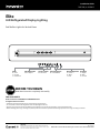
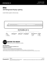
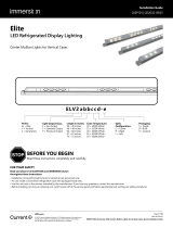
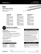
Prex:
EL = Elite
V = Vertical
3 = Generation
Light Output Class:
E = Eco Output
Length in inches:
60 = 60 inches
Color Temperature:
50 = 5000K White
Optic Conguration:
C = Center
R = Right
L = Left
Packaging:
S = Single
B = Bulk
# = Custom
LED.com
© 2023 Current Lighting Solutions, LLC. All rights reserved. Information and
specifications subject to change without notice. All values are design or typical
values when measured under laboratory conditions.
Page 1 of 9
(Rev 06/21/23)
DISP109-RDL-lmmersion-Elite-End-Mullion-Lights-for-Verical-Cases-Gen3-lnstallation-Guide
Installation Guide
DISP109 | A-1022812
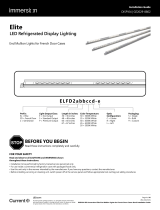
Elite
LED Refrigerated Display Lighting
End Mullion Lights for Vertical Cases
BEFORE YOU BEGIN
Read these instructions completely and carefully.

• The LED driver must be supplied the rated
voltage as listed (LED Driver Compatibility), and
connected to an individual properly grounded
branch circuit, protected by a 15 or 20 ampere
circuit breaker or time delay fuse.
• Wiring must be 2 wire with ground and rated
for 75°C (167°F).
• Do not overload driver. Follow loading
guidelines on page 6 of this installation guide.
• Ensure that all connection points are sealed for
damp location using the appropriate method
per the NEC or local electrical code.
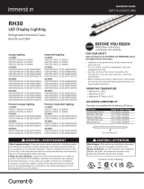
Electrical Requirements Led Driver Compatibility
This system is compatible with the following LED Drivers.
Please refer to the separate LED driver installation
guide for appropriate wiring connections.
6-Door 5-Door 4-Door 3-Door 2-Door
Center LED Lights 5 4 3 2 1
End LED Light Sets 1 1 1 1 1
Wire Covers 7 6 5 4 3
Eco Eco Eco Eco Eco
Using GELP24-60U-GL, GEPS24D-60U-GLX, GEPS6100NCCON-SY, GEPS24D-100U-NA & GELP24-100U-GLX LED Drivers
LED Drivers (60-inch LED Lights) 1 1 1 1 1
Parts Needed Per Case
ImmersionTM Elite Installation Guide
LED.com
© 2023 Current Lighting Solutions, LLC. All rights reserved. Information and
specifications subject to change without notice. All values are design or typical
values when measured under laboratory conditions.
Page 2 of 9
(Rev 06/21/23)
DISP109-RDL-lmmersion-Elite-End-Mullion-Lights-for-Verical-Cases-Gen3-lnstallation-Guide
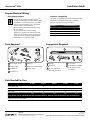
Prepare Electrical Wiring
Tools Required
Wire stripper/cutter
Tape measure
Screwdriver
Cordless drill
Hammer
7/64-inch (2.8mm) drill bit
Center punch
1
1
5
5
2
2
6
6
3
3
7
7
4
4
Components Required
LED light
Wire cover
24-volt, Class 2 (UL),
SELV (CE), LED driver
6-32 screws
UL certied 22-14 AWG
(0.33-2.08 mm2) wire
connectors
1
1
4
4
2
2
5
5
3
3
LED Driver Rated AC Input Voltage
GEPS6100NCCON-SY 120-240VAC, 60/50Hz
GEPS24D-100U-NA 120-277VAC, 60/50Hz
GELP24-100U-GLX 120-277VAC, 60/50Hz
GEPS24D-60U-GLX 120-277VAC, 60/50Hz

ImmersionTM Elite Installation Guide
LED.com
© 2023 Current Lighting Solutions, LLC. All rights reserved. Information and
specifications subject to change without notice. All values are design or typical
values when measured under laboratory conditions.
Page 3 of 9
(Rev 06/21/23)
DISP109-RDL-lmmersion-Elite-End-Mullion-Lights-for-Verical-Cases-Gen3-lnstallation-Guide
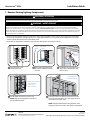
Turn off power to the
refrigeration case.
Remove all lamp guards and
uorescent tubes from inside
the case.
Locate ballast and remove access cover.
NOTE: Refer to the refrigeration manual for
specic ballast location.
Inside the case, cut wires as close
as possible to lampholders and
remove them.
Disconnect wires to ballast and remove from case.
Leave the existing ballast input and output wires for
reconnection in a later step.
NOTE: Follow all federal and local regulations when
disposing of uorescent tubes, transformers and ballasts.
Fluorescent
tubes
Lamp
guards
Remove
lampholders
Leave wire
in place
Possible ballast locations:
- Over door frame
- Inside mullion
- Behind raceway
Remove ballast
Leave existing wiring
• Refer to manufacturing manual for refrigeration case to identify lighting control circuits. Ensure that power is switched
off at the service panel for the lighting circuit. If a lighting power switch is not provided in the refrigeration case, power
removal can be performed at the main breaker panel.
• Please refer to refrigeration manual for any questions dealing with component locations.
1 - Remove Existing Lighting Components
1 2 3
4 5
CAUTION / ATTENTION
Risk of injury. While performing installations described, gloves, safety glasses or goggles should be worn. / Risque de blessure. Lors de l'exécution des
installations décrites, des gants, des lunettes de sécurité ou des lunettes de protection doivent être portées.
WARNING / AVERTISSEMENT
Risk of electrical shock. Disconnect power before servicing or installing product. LED Retrot Kit Installation requires knowledge of luminaires electrical
systems. If not qualied, do not attempt installation. Contact a qualied electrician. Install this kit only in the luminaires that have the construction
features and dimensions shown in the photographs and/or drawings. / Risque de choc électrique. Couper le courant avant de réparer ou installer le
produit. LED Retrot Kit d’installation nécessite la connaissance des systèmes luminaires électriques. Si vous n’êtes pas qualié, ne tentez pas l’installation.
Contactez un électricien qualié. Installez ce kit seulement dans les luminaires qui ont les caractéristiques de construction et les dimensions gurant sur
les photographies et / ou des dessins.

WARNING / AVERTISSEMENT
Risk of re or electric shock. Luminaire wiring and electrical parts may be damaged when drilling for installation of LED retrot kit. Check
for enclosed wiring and components. / Risque de feu ou électrocution. Les pièces et câbles électriques risquent d’être endommagés lors du
perçage des trous pour l’installation du luminaire à DEL. Veuillez vérier si des câbles et composantes se trouvent derrière la paroi avant de
percer.
To prevent wiring damage or abrasion, do not expose wiring to edges of sheet metal or other sharp objects. / Pour éviter l'endommagement de
câblage ou l'abrasion, ne pas exposer le câblage aux bords de feuilles de métal ou d'autres objets tranchants.
ImmersionTM Elite Installation Guide
LED.com
© 2023 Current Lighting Solutions, LLC. All rights reserved. Information and
specifications subject to change without notice. All values are design or typical
values when measured under laboratory conditions.
Page 4 of 9
(Rev 06/21/23)
DISP109-RDL-lmmersion-Elite-End-Mullion-Lights-for-Verical-Cases-Gen3-lnstallation-Guide
WARNING / AVERTISSEMENT
Risk of electrical shock. Only those open holes indicated in the photographs and/or drawings may be made or altered as a result of kit
installation. Do not leave any other open holes in an enclosure of wiring or electric components / Risque de choc électrique. Seuls les trous
ouverts indiqués dans les photos et / ou les dessins peuvent être faites ou modiés à la suite du montage du kit. Ne pas laisser autres trous ouverts
dans l'enceinte du câblage électrique ou composants.
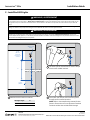
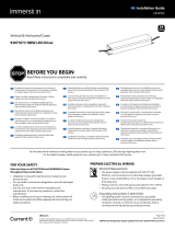
2 - Install End LED Lights
LED Light Length L1
60" 58.09"
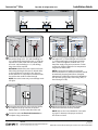
Mark two hole locations on mullion. Use a 7/64" (2.8 mm) bit to drill mounting holes
through the two marked locations.
NOTE: Refer to the manufacturing manual for door
frame to ensure there are no components contained
inside the mullion that could be drilled through.
Use center punch and hammer to create a dimple
over the two marked locations.
Total width
of mullion
1-3/32"
(28mm)
Wires to old
ballast
L1
2-1/8"
(54 mm)
minimum
from top of
mullion
1
2
3

ImmersionTM Elite Installation Guide
LED.com
© 2023 Current Lighting Solutions, LLC. All rights reserved. Information and
specifications subject to change without notice. All values are design or typical
values when measured under laboratory conditions.
Page 5 of 9
(Rev 06/21/23)
DISP109-RDL-lmmersion-Elite-End-Mullion-Lights-for-Verical-Cases-Gen3-lnstallation-Guide
Refer to wiring diagram on page 7. Connect the
red stripe wire (+) of the LED light to the red wire
(+) of the power supply, and connect the white
wire (-) of the LED light to the black wire (-) of
the power supply using wire connectors or other
connection method suitable for low temperature
usage and stranded cable.
NOTE: If connections are made in an area with
excessive moisture or ice, electrical connections should
be sealed with electrical grade silicone. (Examples:
Momentive RTV 6700 Series, Momentive White Blanc
RTV 162, Dow Corning 3140, Dow Corning 3145, or
Dow Corning RTV 748)
Secure the top and bottom of the LED light to
the mullion using a #6 x 1/2" (self-threading) or x
3/4" (self-drilling) sheet metal screws. If using the
optional wire cover, install the cover base as well
and a 3/4" (self-threading) or x 1" (self-drilling)
long screw will be required.
OPTIONAL: Additional screws can be used in the
holes along the length of the bar if desired. Refer
to the manufacturer manual for door frame to
ensure there are no components contained inside
the mullion that could be drilled through.
NOTE: Over-sized screws may cause damage to the
LED light.
If using the optional wire cover, tuck wires inside
and snap the cover top over the cover base.
Repeat steps 1–6 for the other side of the case.
Mount the LED driver in the same location
where the ballast was formerly installed.
NOTE: Refer to the "Parts Needed Per Case" table
on page 2 to determine the proper number of
LED drivers to install.
Proceed to section 4–Electrical Connections to
complete wiring connections.
Optional wire cover Optional wire cover
Red
stripe (+) Red
stripe (+)
Red (+) Red (+)
White (-) White (-)
Black (-) Black (-)
4
6
8
5
7
End
Mullion
End
Mullion
End
Bar
End
Bar
Center
Bar
Center
Mullion
Glass Door Glass Door
Case
Top view of refrigeration case
IMPORTANT: Before proceeding, verify correct orientation of lights.

ImmersionTM Elite Installation Guide
LED.com
© 2023 Current Lighting Solutions, LLC. All rights reserved. Information and
specifications subject to change without notice. All values are design or typical
values when measured under laboratory conditions.
Page 6 of 9
(Rev 06/21/23)
DISP109-RDL-lmmersion-Elite-End-Mullion-Lights-for-Verical-Cases-Gen3-lnstallation-Guide
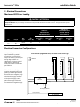
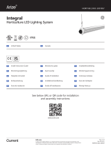
3 - Electrical Connections
Maximum LED Driver Loading
Tier Length
Bar
Type
Light
Bar
Power (W)
LED Driver:
GELP24-60U-GL
GEPS24D-60U-GLX
LED Drivers:
GEPS6100NCCON-SY
GEPS24D-100U-NA
GELP24-100U-GLX
Minimum
Loading QTY
(Min loading >
20W)
Maximum
Loading QTY
(Max loading ~
54W)
Minimum
Loading QTY
(Min loading >
40W)
Maximum
Loading QTY
(Max loading ~
90W)
Eco 60” Center 7.8 3 6 6 10
End 4.3 5 11 10 18
CAUTION / ATTENTION
Risk of injury. Do not overload LED Driver. Do not exceed limits shown in “Maximum LED Driver Loading” table below.
Risque de blessure. Ne pas surcharger l'alimentation. Ne pas exéder les limites de la table cidessous: “Charges maximales pour les
alimentations.”
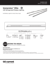
Electrical Connection Congurations
Multiple LED light’s electrical
input should be in parallel
connection to an LED driver’s
output as shown by the example
wiring diagram. Refer to
“Maximum LED Driver Loading”
table above to determine
maximum number of LED lights
per LED driver.
TIP! - ELV3 series LED lights
must be connected in the correct
polarity. If the LED light does not
illuminate when energized, verify
that the white supply conductor
with the red strip is connected
to the positive supply, and the
plain white supply conductor is
connected to the negative supply.
One End Set (Right and Left) and One Center LED Light
TERMINAL BLOCK
(AC SOURCE)
LED
DRIVER
RIGHT END LED LIGHT
LEFT END LED LIGHT
CENTER LED LIGHT
SWITCH
WHITE (NEUTRAL)
BLACK (LINE)
Occupancy Sensor
RED (+)BLACK
BLACK (-)
WHITE
GRAY
RED STRIPE (+)
RED STRIPE (+)
RED STRIPE (+)
PURPLE
WHTIE (-)
WHTIE (-)
WHTIE (-)

ImmersionTM Elite Installation Guide
LED.com
© 2023 Current Lighting Solutions, LLC. All rights reserved. Information and
specifications subject to change without notice. All values are design or typical
values when measured under laboratory conditions.
Page 7 of 9
(Rev 06/21/23)
DISP109-RDL-lmmersion-Elite-End-Mullion-Lights-for-Verical-Cases-Gen3-lnstallation-Guide
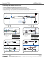
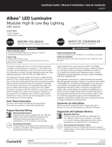
Input
AC line
Dimming
OPTIONAL:
Enable dimming
by cutting loop
Output LED
Occupancy
Sensor
GEPS6100NCCON-SY
Connecting a GEPS6100NCCON-SY Driver
Connect DC output
using 4-way
connector.
Connect DC output
using 4-way
connector.
Connect AC input using wire nuts. Connect DC output using wire nuts.
N
N
L
Ground
Ground
Molex
Connector
Molex Connector
Purple
Purple
Gray
Gray
L
Option Optionor or
• Make input and output connections according to diagrams below.
• Connection methods should be suitable for low temperature usage and standard cable.
• For non-dimming applications, cap the unused wires with 5/32” (4mm) twist on wire connectors.
• For dimming applications, cut the dimming loop on the driver output side and make connections to the occupancy sensor.
• CAUTION: DO NOT apply voltage or power to the switched control circuit – contact closure only.
• Other methods for automated control such as occupancy sensors that switch the AC power side on and off are not recommended and
will void the product warranty.
White (–)
Red stripe (+)
White (–)
Red stripe (+)
Wire Cavity Table
Molex 39-01-4046 (DC)
Cavity 1 - Output DC (+) (Red)
Cavity 2 - Output DC (-) (Black)
Cavity 3 - Dimming (Purple)
Cavity 4 - Dimming (Gray)
Wire Cavity Table
39-01-4030 (AC)
Cavity 1 - Line 1 (Black)
Cavity 2 - Earth Ground (Green)
Cavity 3 - Neutral or Line 2 (White)
A
A
B D
C
C D
B

ImmersionTM Elite Installation Guide
LED.com
© 2023 Current Lighting Solutions, LLC. All rights reserved. Information and
specifications subject to change without notice. All values are design or typical
values when measured under laboratory conditions.
Page 8 of 9
(Rev 06/21/23)
DISP109-RDL-lmmersion-Elite-End-Mullion-Lights-for-Verical-Cases-Gen3-lnstallation-Guide
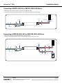
Input
Output
LED
NL
Ground
White (–)
Pink (–)
(–)
Red
stripe (+)
Purple (+)
(+)
Dimming
Controller
Connecting a GELP24-60U-GL or GELP24-100U-GLX Driver
• Make input and output connections according to diagrams below.
• Connection methods should be suitable for low temperature usage and standard cable.
Input
Output
LED
NL
Ground
White (–)
Red stripe (+)
Connecting a GEPS24D-60U-GLX or GEPS24D-100U-NA Driver
• Make input and output connections according to diagrams below.
• Connection methods should be suitable for low temperature usage and standard cable.

ImmersionTM Elite Installation Guide
LED.com
© 2023 Current Lighting Solutions, LLC. All rights reserved. Information and
specifications subject to change without notice. All values are design or typical
values when measured under laboratory conditions.
Page 9 of 9
(Rev 06/21/23)
DISP109-RDL-lmmersion-Elite-End-Mullion-Lights-for-Verical-Cases-Gen3-lnstallation-Guide
Electrical products must not be thrown out with domestic waste. They must be taken to a communal collecting
point for environmentally friendly disposal in accordance with local regulations. Contact your local authorities
or stockist for advice on recycling. The packaging material is recyclable. Dispose of the packaging in an
environmentally friendly manner and make it available for the recyclable material collection-service.
It is advised that a periodic inspection be made of the refrigerated display case and LED lights for proper function. If excessive
moisture or ice buildup is noted, this may be a sign that the door seal is damaged and should be replaced. Please note that
prolonged exposure of the LED lights to moisture and ice may result in damage to the LED lights. Any LED lights exhibiting signs of
damage such as discoloration or LEDs that are out should be replaced.
• The outer lens should be cleaned periodically with a mild
liquid dish detergent.
• Do not use chemical cleaners to clean the lens.
• Keep the outside clean. Wipe with a clean cloth lightly
dampened with mild liquid dish detergent. Dry with a
clean, soft cloth.
Cleaning Instructions
Periodic Inspection
• Do not wipe the lens with a soiled dish cloth or wet towel.
These may leave a residue that can damage the nish.
• Do not use scouring pads, powdered cleaners, bleach or
cleaners containing bleach because these products can
scratch and damage the nish.
This product is intended solely for the use of commercial refrigerated, display
or case lighting and is not intended for use in any other application.
This device complies with part 15 of the FCC Rules. Operation is subject to the following two conditions: (1) This device may not cause harmful interference, and
(2) this device must accept any interference received, including interference that may cause undesired operation.
NOTE: This equipment has been tested and found to comply with the limits for a Class A digital device, pursuant to part 15 of the FCC Rules. These limits are
designed to provide reasonable protection against harmful interference when the equipment is operated in a commercial environment. This equipment
generates, uses, and can radiate radio frequency energy and, if not installed and used in accordance with the instruction manual, may cause harmful interference
to radio communications. Operation of this equipment in a residential area is likely to cause harmful interference in which case the user will be required to
correct the interference at his own expense.
This Class [A] RFLD complies with the Canadian standard ICES-005. /CeDEFR de la classe [A] est conforme à la NMB-005 du Canada.
WARNING / AVERTISSEMENT
-
 1
1
-
 2
2
-
 3
3
-
 4
4
-
 5
5
-
 6
6
-
 7
7
-
 8
8
-
 9
9


Immersion Elite Gen 3 Vertical Case End Mullion Lights Guide d'installation
- Taper
- Guide d'installation
dans d''autres langues
Documents connexes
-
 Immersion Elite Gen 3 Vertical Case Center Mullion Lights Guide d'installation
-
 Immersion Elite Gen 2 French Door End Mullion Lights Guide d'installation
-
 Immersion Elite Gen 2 Vertical Case Center Mullion Lights Guide d'installation
-
 Immersion LED DIsplay Lighting Elite Series Horizontal Guide d'installation
-
 Immersion RH30 12/24/36/48 Inch Guide d'installation
-
 Immersion GELP24-100U-GLX Power Supply Guide d'installation


Autres documents
-
 GE current DISP104 Guide d'installation
-
GE current DISP103 Guide d'installation
-
 ARIZE Integral Guide d'installation
-
Tetra Contour LS LED Signage Guide d'installation
-
-
-
-
-
 Albeo de Léclairage Modulaire des Baies Hautes et Basses de la Série ABC Guide d'installation
-
Lumination RUL Series LED Refit Universal Linear Kit Guide d'installation


