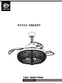
Parrot Uncle F4722-SMART Chrome Smart Crystal Retractable Ceiling Fan Manuel utilisateur
- Taper
- Manuel utilisateur

F4722-SMART

F4722-SMART
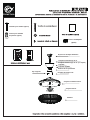
F4722-SMART 110-120 VAC 65W 5*E26 MAX.25W
Light
SKU

F4722-SMART
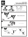
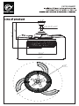
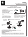
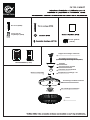
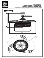
Embossed nut
(4PCS)
light
s hade

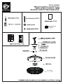
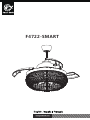
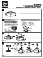
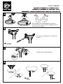
Take the finished F4722-SMART out of the packing box
F4722-SMART
1
2
3

F4722-SMART
Finish
INSERT
BIUE
BLACK
WHITE

F4722-SMART
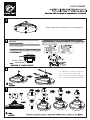
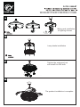
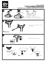
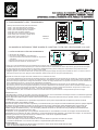
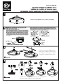
Wiring and installation
of lighting fixtures
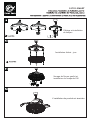
Lamp shade installation
Tighten the embossed nut
and install the E26 bulb
The product installation is complete

F4722-SMART
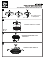
Remote controller
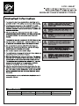
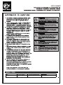
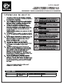
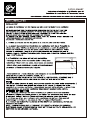
INSTRUCTION OF INSTALLATION AND OPERATION
1.INSTALLING RECEIVER IN CEILING FAN
A. Safety precautions:
WARNING: HIGH VOLTAGE! Disconnect power by
removing fuse or switching off circuit breaker.
Do not use with solid state fans.
Electrical wire must meet all local and national
electrical code requirements.
Supply for fan must be 110/120 volt, 60Hz. Maximum
fan motor amps: 1.0, Maximum light watts: 180
incandescent or ballast and LED.
Otherwise power can cause serious injury or death.
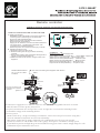
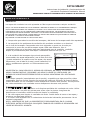
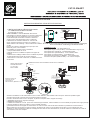
B. Installing receiver in fan:
a. Remove power from the circuit.
b. Remove ceiling fan canopy from the mounting
bracket.
c. Disconnect existing wiring between ceiling fan and
Supply in electrical junction box.
d. Make connections as follows, using the wire nuts
supplied:
CONNECT TO
Green fan wire ....Bare supply wire
Red or Black receiver wire(AC IN L) ....Red or Black supply wire
White receiver wire(AC IN N) ....White supply wire
White receiver wire(TO MOTOR N) ....White fan wire
Black receiver wire(TO MOTOR L) ....Black fan wire
Blue receiver wire(FOR LIGHT) ....Blue light wire
Purple receiver wire(FOR REV) ....Purple rev wire
Use wire connecting nuts supplied with the fan
(FIG.3)
FROM POWER SOURCE
AC 110~120 VOLT 60Hz
3.5AMPS.
TRANSMITTER
LEARN
CODE
COM
COD E
ACN ACL
ANT
COM
FAN
LIGHT
INPUT
OUTPUT
RECEIVER
FIG.1
REV
WHITE
INPUT
OUTPUT
RED or BLACK
BLUE
ANT
CANOPY
BLACK
WHITE
Use wire connecting nuts
supplied with the remote
controller.
WIRE NUT
RECEIVER
PURPLE
REV MODULE
white
black
purple
orange
yellow
grey
white
black
purple
orange
yellow
grey
RECEIVER
CANOPY
(
FIG.4
)
ANTENNA PUT AT OUTSIDE
OF CANOPY BOX CAN GET
MORE OPERATION
DISTANCE
CAUTION:Ceiling Angle Shall Not Exceed 30 Degrees,For Mounting Controller,Model:RE-028W

F4722-SMART
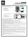
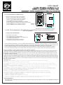
2. OPERATING TRANSMITTER:
Operating the buttons on the panel of the transmitter.
3 key -for fan high speed.
2 key-for fan medium speed.
1 key-for fan low speed.
OFF key-for fan off.
REV key-for fan rev.
LIGHT key-for light on and off.
LIGHT+ key-for light dimmer +.
LIGHT- key-for light dimmer -.
YOUR REMOTE NOW HAS FULL CONTROL OF THE FAN AND LIGHT.
3. TROUBLE SHOOTING GUIDE
a. Power to receiver ?
b. Receiver wired correctly ?
c. Fan manual speed control in highest position ?
d. Light kit switch turned on ?
e. Good battery in the transmitter ?
OPERATION DISTANCE 20 FEET
MODEL:
RE-021
WARNING
TO REDUCE THE RISK OF SHOCK, THIS FAN MUST BE INSTALLED WITH A WALL CONTROL/SWITCH.
TRANSMITTER
LEARN
CODE
COM
COD E
ACN ACL
ANT
COM
FAN
LIGHT
INPUT
OUTPUT
RECEIVER
FIG1
REV
If there are two or more ceiling fans installed in the same house, in order to prevent your ceiling fans from being
affected by the remote control of the adjacent ceiling fans, first turn the switch in each remote control
transmitter to the CODE(locked) position (see the schematic diagram FIG1) Remarks: The standard state
of the transmitter is in the common code COM.
(Power-off means you need to use a wall switch to shut down the power of the ceiling fan, if you do not
have a wall switch, please power off the whole room from the air circuit-breaker for each room)
After installing the remote control receiver on the ceiling fan
1: Turn on the power of the 1# ceiling fan receiver (the power of the 2# receiver is kept in a power-off state),
within 30 seconds after the fan power is turned on, press the LEARN button corresponding to the 1#
transmitter, then The receiver will learn the transmitter code. When the transmitter code is learned successfully, the light of the
ceiling fans will flash twice, and then it can be used normally.
2: Turn on the power of the 2# ceiling fan receiver (the power of the 1# receiver is kept in the power-off state), within 30 seconds
after the fan power is turned on, press the LEARN button corresponding to the 2# transmitter, then The receiver will learn the
transmitter code.
When the transmitter code is learned successfully, the light of the ceiling fans will flash twice, and then it can be used normally.
And so on, only one ceiling fan is powered on each time the corresponding transmitter learns.
FCC Statement:
1.This device complies with Part 15 of the FCC Rules. Operation is subject to the following two conditions: (1) This device
may not cause harmful interference.
(2) This device must accept any interference received, including interference that may cause undesired operation. 2. Changes
or modifications not expressly approved by the party responsible for compliance could void the user's authority to operate the
equipment.
NOTE: This equipment has been tested and found to comply with the limits for a Class B digital, pursuant to Part 15 or the
FCC Rules. These limits are designed to provide reasonable protection against harmful interference in a residential installation.
This equipment generates, uses and can radiate radio frequency energy and, if not installed and used in accordance with the
instructions, may casue harmful interference to radio communications,
However, there is no guarantee that interference will not occur in a particular installation. If the equipment does cause harmful
interference to radio or television reception, which can be determined by turning the equipment off and on, the user is
encouraged to try to correct the interference by one or more of the following measures: --- Reorient or relocate the receiving
antenna.
--- Increase the separation between the equipment and receiver. --- Connect the equipment into an outlet on a circuit different
from that to which the receiver is connected.
--- Consult the dealer or an experienced radio/ TV technician for help.

F4722-SMART
φ
5.9"
20.4"
23.6"
14"
26.5*4"or10"
52"
φ
φ
52"

F4722-SMART

F4722-SMART

F4722-SMART
F4722-SM ART5 *E 2 6 MAX.
25W65W110-120VAC

F4722-SMART
Tornillos para madera (4pzas)
Tuerca para alambre
de plástico (3pzas)
Pantalla
Conjunto kit luz
Conjunto ventilador-motor
Soporte de montaje deslizante
Conjunto bola/vástago de 4"
Conjunto bola/vástago de 10" (en espera)
Tejadillo
Tapa del tejadillo
Cubierta de acoplamiento
Pasador de bloqueo “R”
Eje colgante
Tuerca estampada
(4pzas)

F4722-SMART
Saque el F4722-SMART acabado de su caja de embalaje
Destornillador
Phillins
Destornillador
Phillins
1
2
3

F4722-SMART
Terminado
INSERTAR
BIUE
BLACK
WHITE
Terminado
Destornillador Phillins

F4722-SMART
Wiring and installation
of lighting fixtures
Esquema de instalación de la pantalla
Apriete la tuerca estampada e instale
la bombilla E26
Instalación completa del producto

Mando a distancia
INSTRUCCIONES DE INSTALACIÓN Y FUNCIONAMIENTO
1.INSTALACIÓN DEL RECEPTOR EN EL
VENTILADOR DE TECHO
A: Precauciones de seguridad:
ADVERTENCIA: ALTA TENSIÓN! Desconecte la alimentación
quitando el fusible o desconectando el disyuntor.
No utilizar con ventiladores de estado sólido.
El cable eléctrico debe cumplir todos los requisitos de los
códigos eléctricos locales y nacionales.
El suministro para el ventilador debe ser de 110/120 voltios,
60 Hz. Amperios máximos del motor del ventilador: 1,0,
vatios máximos de la luz: 180 incandescentes o balasto y LED.
De lo contrario, la alimentación puede causar lesiones graves
o la muerte.
B: Instalación del receptor en el ventilador:
a. Desconecte la alimentación del circuito.
b. Retire la cubierta del ventilador de techo del soporte de montaje.
c. Desconecte el cableado existente entre el ventilador de techo
y el suministro en la caja de conexiones eléctricas.
d. Realice las conexiones como se indica a continuación,
utilizando las tuercas para cables suministradas:
CONECTAR A Alambre
Cable verde del ventilador ....Cable desnudo de alimentación
Cable receptor rojo o negro (AC EN L)....Cable de alimentación rojo o negro
Cable receptor blanco (AC EN N)....Cable de alimentación blanco
Cable blanco del receptor (AU MOTOR N)....Cable blanco del ventilador
Cable negro del receptor (AU MOTOR L)....Cable negro del ventilador
Hilo receptor azul (PARA LUZ) ....Hilo azul luz
Hilo receptor violeta (PARA REV) ....Hilo receptor violeta
Utilice las tuercas de conexión suministradas con el ventilador
(FIG.3)
DE UNA FUENTE DE
ALIMENTACIÓN AC
110- 120 VOLT 60Hz
3.5AMPS.
TRANSMISOR
CONOZCA
CODE
COM
COD E
ACN ACL
ANT
COM
VENTILADOR
LUZ
ENTRADA
SALIDA
RECEPTOR
FIG.1
REV
BLANCO
ENTRADA
SALIDA
ROJO o NEGRO
AZUL
ANT
TOLDO
NEGRO
BLANCO
Utilice las tuercas de conexión
de cables suministradas con
el mando
a distancia.
TUERCA DE ALAMBRE
RECEPTOR
VIOLETA
REV MÓDULO
blanco
negro
violeta
naranja
amarillo
gris
white
black
purple
orange
yellow
grey
RECEPTOR
TOLDO
(
FIG.4
)
ANTENA EXTERIOR MÁS
TEJADILLO CAJA
FUNCIONAMIENTO
PUEDE CONSEGUIR DISTANCIA
Si otros ventiladores o cables de alimentación son de otro color, encargue la instalación de esta unidad
a un electricista cualificado y autorizado.
a.Empuje todos los cables conectados hacia arriba en la caja de conexiones.
b.Coloque el cable de antena marrón sobre el receptor, y coloque el receptor en el soporte de montaje.
c. Vuelva a instalar la cubierta en el soporte de montaje.
d. Restablezca la alimentación eléctrica.
e. Instale una pila de 3.0 voltios . (Para evitar daños en el transmisor, retire la batería si no va a utilizarlo durante un
periodo prolongado).
f. Guarde el transmisor alejado del calor o la humedad excesivos.
g. Este mando a distancia está equipado con combinaciones de códigos de rodillo. Para evitar posibles interferencias
con otros mandos a distancia como abridores de puertas de garaje, alarmas de coche o sistemas de seguridad. Si observa
que el ventilador y el kit de luces se encienden y apagan sin la ayuda del mando a distancia, sólo tiene que cambiar la
combinación de códigos del transmisor y del receptor.
PRECAUCIÓN: El ángulo del techo no debe superar los 30 grados,Para el controlador de
montaje, modelo RE-028W
PULSE
RELEASE
F4722-SMART

F4722-SMART
2. FUNCIONAMIENTO DEL TRANSMISOR:
Manejo de los botones del panel del transmisor.
Tecla 3 -para velocidad alta del ventilador.
Tecla 2 -para velocidad media del ventilador.
Tecla 1-para velocidad baja del ventilador.
Tecla OFF-para ventilador apagado.
Tecla REV-para revoluciones del ventilador.
Tecla LIGHT-para encender y apagar la luz.
Tecla LIGHT+ para regular la luz +.
Tecla LIGHT- para atenuar la luz -.
SU MANDO A DISTANCIA TIENE AHORA EL CONTROL TOTAL DEL VENTILADOR Y LA LUZ.
3. GUÍA DE RESOLUCIÓN DE PROBLEMAS
a. Encendido del receptor?
b. El receptor está cableado correctamente?
c. Control manual de velocidad del ventilador en la posición
más alta?
d. El interruptor del kit de luces está encendido?
e. Batería en buen estado en el transmisor?
DISTANCIA DE FUNCIONAMIENTO 20 PIES
MODELO:
RE-021
Si hay dos o más ventiladores de techo instalados en la misma casa, para evitar que sus
ventiladores de techo se vean afectados por el mando a distancia de los ventiladores de techo adyacentes, gire primero el interruptor
de cada transmisor de mando a distancia a la posición CODE(bloqueado) (véase el diagrama esquemático FIG1) Observaciones:
El estado estándar del transmisor es en el código común COM.
(Apagado significa que usted necesita usar un interruptor de pared para apagar la energía del ventilador de techo, si usted no tiene un
interruptor de pared, por favor apague toda la habitación desde el disyuntor de aire para cada habitación)
Después de instalar el receptor del mando a distancia en el ventilador de techo
1: Conecte la alimentación del receptor del ventilador de techo 1# (la alimentación del receptor 2# se mantiene en estado de apagado),
en los 30 segundos siguientes a la conexión de la alimentación del ventilador, pulse el botón LEARN correspondiente al transmisor 1#,
entonces El receptor aprenderá el código del transmisor. Cuando el código del transmisor se aprenda con éxito, la luz del ventilador de
techo parpadeará dos veces, y entonces se podrá utilizar normalmente.
2: Conecte la alimentación del receptor del ventilador de techo 2# (la alimentación del receptor 1# se mantiene en estado de
desconexión), dentro de los 30 segundos después de conectar la alimentación del ventilador, pulse el botón LEARN correspondiente al
transmisor 2#, entonces El receptor aprenderá el código del transmisor. Cuando el código del transmisor se aprenda con éxito, la luz
del ventilador de techo parpadeará dos veces, y entonces se podrá utilizar normalmente.
Y así sucesivamente, sólo un ventilador de techo se enciende cada vez que el transmisor correspondiente aprende el código.
s
.
Declaración FCC:
1.Este dispositivo cumple con la Parte 15 de las normas de la FCC. Su funcionamiento está sujeto a las dos condiciones siguientes
(1) Este dispositivo no puede causar interferencias perjudiciales.
(2) Este dispositivo debe aceptar cualquier interferencia recibida, incluyendo interferencias que puedan causar un funcionamiento
no deseado.
2. Los cambios o modificaciones no aprobados expresamente por la parte responsable del cumplimiento podrían anular la
autoridad del usuario para utilizar el equipo.
NOTA: Este equipo ha sido sometido a pruebas y se ha determinado que cumple los límites establecidos para los equipos digitales
de Clase B, de conformidad con la Parte 15 de las normas de la FCC. Estos límites están diseñados para proporcionar una
protección razonable contra interferencias perjudiciales en una instalación residencial. Este equipo genera, utiliza y puede
irradiar energía de radiofrecuencia y, si no se instala y utiliza de acuerdo con las instrucciones, puede provocar interferencias
perjudiciales en las comunicaciones por radio,
No obstante, no se garantiza que no se produzcan interferencias en una instalación concreta. Si el equipo causa interferencias
perjudiciales en la recepción de radio o televisión, lo cual puede determinarse apagando y encendiendo el equipo, se recomienda
al usuario que intente corregir la interferencia mediante una o más de las siguientes medidas:
--- Reorientar o reubicar la antena receptora.
--- Aumentar la separación entre el equipo y el receptor.
--- Conecte el equipo a una toma de corriente de un circuito distinto al que está conectado el receptor.
--- Consulte al distribuidor o a un técnico de radio/ TV experimentado para obtener ayuda.
ADVERTENCIA
PARA REDUCIR EL RIESGO DE DESCARGA ELÉCTRICA, ESTE VENTILADOR DEBE INSTALARSE
CON UN MANDO/INTERRUPTOR DE PARED.
TRANSMISOR
CONOZCA
CODE
COM
COD E
ACN ACL
ANT
COM
VENTILADOR
LUZ
ENTRADA
SALIDA
RECEPTOR
FIG1
REV
RELEASE
PULSE
CONOZCA

F4722-SMART
φ
5.9"
20.4"
23.6"
14"
26.5*4"or10"
52"
φ
φ
52"
Dimensión del producto

F4722-SMART
Instrucciones de instalación y funcionamiento del
ADVERTENCIA: CORTE LA CORRIENTE CON EL FUSIBLE O EL DISYUNTOR
parrotuncle Propietarios Instalación ,Manual
DESPUÉS DE LA INSTALACIÓN
OSCILACIÓN"
Las aspas del ventilador han sido ajustadas en fábrica para minimizar cualquier oscilación.
NOTA: LOS VENTILADORES DE TECHO TIENDEN A MOVERSE DURANTE SU FUNCIONAMIENTO PORQUE
ESTÁN MONTADOS SOBRE UNA ARANDELA DE GOMA. SI EL VENTILADOR ESTUVIERA MONTADO
RÍGIDAMENTE EN EL TECHO, PROVOCARÍA VIBRACIONES EXCESIVAS. UN MOVIMIENTO DE POCOS
CENTÍMETROS ES PERFECTAMENTE ACEPTABLE Y NO PLANTEA NINGÚN PROBLEMA.PARA REDUCIR LA
OSCILACIÓN DEL VENTILADOR: COMPRUEBE QUE TODOS LOS TORNILLOS QUE FIJARON EL MONTAJE
EL SOPORTE Y LA VARILLA ESTÁN BIEN FIJADOS.
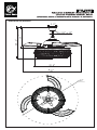
EQUILIBRAR UN VENTILADOR DE TECHO OSCILANTE:
1. Compruebe que todos los tornillos de las aspas y del brazo de las aspas están bien apretados.
2. La mayoría de los problemas de oscilación del ventilador se deben a un desnivel
en el nivel de las aspas. Compruebe este nivel eligiendo un punto en el techo por
encima de la punta de una de las aspas. aspas. Mida esta distancia. Gire el
ventilador hasta que el siguiente aspa esté posicionada para la medición. medición.
Repita el procedimiento para cada aspa. La distancia debe ser de 0,32 cm.
3. si la oscilación de las aspas sigue siendo perceptible,
intercambiar dos aspas adyacentes (una al lado de la otra
) puede redistribuir el espacio entre las aspas. dos aspas
adyacentes (una al lado de la otra) puede redistribuir el
peso y posiblemente permitir un funcionamiento más
suave.
ADVERTENCIA: PARA REDUCIR EL RIESGO DE LESIONES, NO DOBLE EL BRAZO DE LAS
ASPAS CUANDO INSTALE, EQUILIBRE LAS ASPAS O LIMPIE EL VENTILADOR. NO
INTRODUZCA OBJETOS EXTRAÑOS ENTRE LAS ASPAS GIRATORIAS DEL VENTILADOR.
RUIDO
Con tiempo tranquilo (especialmente por la noche), es posible que oiga pequeños ruidos
ocasionales. Esto es normal. Permita un período de rodaje de 24 horas; la mayoría de los
ruidos asociados con un ventilador nuevo desaparecen durante este período. La mayoría de
los ruidos asociados a un ventilador nuevo desaparecen durante este periodo.
7 MANTENIMIENTO Y LIMPIEZA
1. El único mantenimiento necesario es la limpieza periódica del ventilador de techo. Utilice
un cepillo suave o un paño sin pelusa para evitar rayar la pintura. Asegúrese de
desconectar el suministro eléctrico antes de limpiar su ventilador.
2. No utilice agua para limpiar el ventilador de techo. Podría dañar el motor o las aspas y
provocar una descarga eléctrica.
3. El motor está equipado con un rodamiento de bolas de lubricación permanente. No es
necesario engrasarlo.
NOTA: ASEGÚRESE DE QUE LA CORRIENTE ESTÁ DESCONECTADA EN EL CUADRO
ELÉCTRICO ANTES DE REALIZAR CUALQUIER TRABAJO DE LIMPIEZA O REPARACIÓN. NO
LIMPIE NI REPARE EL APARATO.
Botón de techo
La page est en cours de chargement...
La page est en cours de chargement...
La page est en cours de chargement...
La page est en cours de chargement...
La page est en cours de chargement...
La page est en cours de chargement...
La page est en cours de chargement...
La page est en cours de chargement...
La page est en cours de chargement...
La page est en cours de chargement...
La page est en cours de chargement...
-
 1
1
-
 2
2
-
 3
3
-
 4
4
-
 5
5
-
 6
6
-
 7
7
-
 8
8
-
 9
9
-
 10
10
-
 11
11
-
 12
12
-
 13
13
-
 14
14
-
 15
15
-
 16
16
-
 17
17
-
 18
18
-
 19
19
-
 20
20
-
 21
21
-
 22
22
-
 23
23
-
 24
24
-
 25
25
-
 26
26
-
 27
27
-
 28
28
-
 29
29
-
 30
30
-
 31
31


Parrot Uncle F4722-SMART Chrome Smart Crystal Retractable Ceiling Fan Manuel utilisateur
- Taper
- Manuel utilisateur
dans d''autres langues
Documents connexes
-
Parrot Uncle F3531CH110V Guide d'installation
-
-
-
-
-
-