Caleffi H0008338 - PresCal HP High Range PRV Mode d'emploi
- Taper
- Mode d'emploi

1
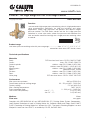
PresCal™ HP High Range PRV for First Stage Control
536 Series
The 536 Series high range pressure reducing valve is a high performance
valve manufactured specifically for high-rise buildings and other
applications where high pressures are present and require staged
pressure control. The 536 Series carries out the first stage pressure
reduction in a two valve series where the pressure ratio between the
inlet and outlet would be too high for a single pressure reducing valve
to control.
H0008338.03
536 Series pressure reducing valve with pressure gauge....................sizes ½”, ¾”, 1”, 1-¼”, 1-½”, 2”
connections dual union; NPT female, sweat
Product range
Function
Technical specifications
Materials
Body: DZR low-lead cast brass CR EN 1982 CC768S
Cover: brass EN 12165 CW617N
Control spindle: stainless steel EN 10088-3 (AISI 303)
Spring: stainless steel ISO 6931-1 (4310-301-00)
Moving parts: stainless steel EN 10088-3 (AISI 303)
Seals: peroxide-cured EPDM
Strainer: stainless steel EN 10088-2 (AISI 304)
Seat: stainless steel EN 10088-3 (AISI 303)
Valve plug: DZR low-lead brass CR EN 12165 CW724R
Performance
Max. pressure upstream: 360 psi (2500 kPa)
Downstream pressure setting range: 90 - 150 psi (600 - 1000 kPa)
Factory setting: 115 psi (800 kPa)
Max. working temperature: 180°F (80°C)
Pressure gauge scale: 0 - 200 psi (0 - 1400 kPa)
Filter mesh size
(diameter)
: size ½” - 1”: 0.2 (0.51 mm)
size 1¼” - 2”: 0.3 (0.65 mm)
Medium: Water
Flow rate: see graph
Complies with NSF/ANSI/CAN 61 and NSF/ANSI/CAN 372, Drinking Water System Components-
Lead Content Reduction of Lead in Drinking Water Act, California Health and Safety Code 116875
S.3874, Reduction in Drinking Water Act, Vermont Act 193 - The Lead in Plumbing Supplies Law and
Maryland’s Lead Free Law HB.372, as certified by ICC-ES, file PMG-1360.
© Copyright 2023 Caleffi
www.caleffi.com
NSF/ANSI/CAN 61
NSF/ANSI/CAN 372

SAFETY INSTRUCTION
WARNING: This product can expose you to chemicals including lead, which
is known to the State of California to cause cancer and birth defects or other
reproductive harm. For more information go to www.P65Warning.ca.gov.
CAUTION: Caleffi shall not be liable for damages resulting from stress
corrosion, misapplication or misuse of its products.
CAUTION: All work must be performed by qualified personnel trained in the
proper application, installation, and maintenance of systems in accordance
with all applicable codes and ordinances.
CAUTION: If the pressure reducing valve is not installed, commissioned and
maintained properly, according to the instructions contained in this manual, it
may not operate correctly and may endanger the user.
CAUTION: Make sure that all the connecting pipework is water tight.
CAUTION: Over-tightening and breakage can occur with the use of Teflon®
pipe joint compounds. Teflon® provides lubricity so that care must be
exercised not to over-tighten joints . Failure to follow these instructions could
result in property damage and /or personal injury.
CAUTION: System fluids are under pressure or temperature can be
hazardous. Be sure the pressure has been reduced to zero and the system
temperature is below 100°F (38°C ). Failure to follow these instructions
could result in property damage and/or personal injury.
Caleffi shall not be liable for damages resulting from stress corrosion, misapplication or
misuse of its products..
This safety alert symbol will be used in this manual to draw attention to safety related
instructions. When used, the safety alert symbol means ATTENTION! BECOME ALERT!
YOUR SAFETY IS INVOLVED! FAILURE TO FOLLOW THESE INSTRUCTIONS
MAY RESULT IN A SAFETY HAZARD.
2

3
CONSIGNE DE SÉCURITÉ
AVERTISSEMENT: Ce produit peut vous exposer à des produits chimiques
comme le plomb, qui est connu dans l’État de Californie pour causer le
cancer, dommages à la naissance ou autre. Pour plus d’informations rendez-
vous www.P65Warnings.ca.gov.
AVERTISSEMENT: Caleffi ne sera pas responsable des dommages résultant
de la corrosion sous tension, d’une mauvaise application ou d’une mauvaise
utilisation de ses produits.
AVERTISSEMENT: Tous les travaux doivent être effectués par du personnel
qualifié formé à la bonne application, installation et maintenance des
systèmes conformément aux codes et règlements locaux.
AVERTISSEMENT: Si le réducteur de pression n’est pas installée, mis en
service et entretenu correctement, selon les instructions contenues dans ce
manuel, il peut ne pas fonctionner correctement et peut mettre en danger
l’utilisateur.
AVERTISSEMENT: S’assurer que tous les raccordements sont étanches.
AVERTISSEMENT: Un serrage excessif et une rupture peuvent survenir
avec l’utilisation de Teflon® composés de joint de tuyau. Le Teflon® offre un
pouvoir lubrifiant de sorte que les soins doivent être exercé pour ne pas
trop serrer les joints. Non-respect de ces instructions pourrait entraîner des
dommages matériels et / ou des blessures corporelles.
AVERTISSEMENT: Les fluides du système sont sous pression ou la
température peut être hasardeux . Assurez vous que la pression a été
réduite à zéro et que le La température du système est inférieure à 38°
C (100° F). Non-respect de ces Les instructions peuvent entraîner des
dommages matériels et / ou des blessures corporelles.
Caleffi ne pourra etre tenue responsable des dommages resultant de la corrosion, d’une
mauvaise utilisation ou une mauvaise utilisation des produits.
Ce symbole d’avertissement servira dans ce manuel à attirer l’attention sur la sécurité
concernant instructions. Lorsqu’il est utilisé, ce symbole signifie. ATTENTION! DEVENEZ
ALERTE ! VOTRE SÉCURITÉ EST EN JEU ! NE PAS SUIVRE CES INSTRUCTIONS PEUT
PROVOQUER UN RISQUE DE SECURITE.

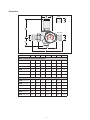
Dimensions
4
Weight (kg)
DN
15
20
25
32
40
1/2”
3/4”
1”
1 1/4”
1 1/2”
140
160
180
204
220
76
90
95
110
120
53,5
53,5
53,5
62,8
62,8
85,3
115,7
115,7
135,2
135,2
bar
ABB' C D E
53,5
54
54
63
63
1,5
2
2,3
3,4
4
sweat
press*
NPT female
|
|
|
|
|
|
|
|
|
|
|
|
|
|
|
|
|
|
|
|
|
|
|
|
|
|
|
|
|
|
|
|
|
|
|
|
|
|
|
|
|
|
|
|
|
|
|
|
|
|
|
|
|
|
|
|
|
|
|
|
|
|
|
|
|
|
|
|
|
|
|
|
|
|
|
|
|
|
|
|
|
|
|
|
|
|
|
|
|
|
|
|
|
|
|
|
|
|
|
|
|
|
|
|
|
|
|
|
|
|
|
|
|
|
|
|
|
|
0
60
20
40
80
100
0
1
25
6
7
34
psi
bar
bar
Code A B B’ C D E Wt. (lb.)
NPT Female threaded connections
536043A 103 1⁄2" 5½” 3" 21⁄8" 33⁄8" 21⁄8" 3.3
536053A 103 3⁄4” 6¼" 3½” 21⁄8” 49⁄16” 21⁄8” 4.4
536063A 103 1” 67⁄8” 33⁄4” 21⁄8” 49⁄16” 21⁄8” 5.0
536073A 103 11⁄4” 77⁄8" 45⁄16" 2½" 51⁄4” 2½” 7.5
536083A 103 11⁄2” 8" 43⁄4” 2½” 51⁄4” 2½” 8.8
536093A 103 2” 85⁄16" 51⁄16” 2½” 51⁄4” 2½” 11.0
Sweat connections
536043A 109 1⁄2" 55⁄8” 3" 21⁄8" 33⁄8” 21⁄8" 3.3
536053A 109 3⁄4” 59⁄16" 3½” 21⁄8” 43⁄8” 21⁄8” 4.4
536063A 109 1” 67⁄8” 33⁄4” 21⁄8” 49⁄16” 21⁄8” 5.0
536073A 109 11⁄4” 65⁄8” 45⁄16" 2½" 51⁄4” 2½” 7.5
536083A 109 11⁄2” 73⁄4" 43⁄4” 2½” 51⁄4” 2½” 8.8
536093A 109 2” 715⁄16" 51⁄16” 2½” 51⁄4” 2½” 12
kPa
psi

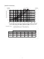
Hydraulic characteristics
Reference values: Upstream pressure = 232 psi (1,600 kPa)
Downstream pressure = 116 psi (800 kPa)
Design Flow Rate (High Range series)
Size ½" ¾" 1" 1¼" 1½" 2"
gpm 4 to 7.3 7 to 12.5 10 to 19 17 to 34 24 to 44 37 to 70
lpm 15 to 27 26 to 47 37 to 72 64 to 129 90 to 166 140 to 265
m3/hr 1 to 1.7 1.6 to 2.9 2.3 to 4.3 3.8 to 7.7 5.4 to 10 8.4 to 16
5
∆p (PSI)
0. 5
1
2
5
10
20
40
0.2
536A I stage
20
15
10
8
6
5
1
2
3
4
10
20
30
40
50
1”
2”
1 ½”
½”
¾”
1 ¼”
(m
3
/hr)
GPM
5
8
FALL OFF PRESSURE
∆p (kPa)
50
100
150
30
40
60
80
120
90
70

Mounting orientation:
1) Before installing the pressure reducing valve, open all the outlets to flush the system and expel
any air or debris in the piping system.
2) Install shut-off valves upstream and downstream to provide for maintenance.
3) The pressure reducing valve can be installed in either vertical or horizontal pipework. However
it must not be installed upside down.
h The pressure gauge may be installed on either side of the valve body. USE THE ADAPTER, do
not screw the gauge directly into the valve body gauge tap. The gauge has MNPT threads and
the valve body gauge tap is straight BSPP.
5) Adjust set point by means of the pressure regulating nut located under the cover, turning with
a 10 mm hexagonal Allen key to increase the set value or counter clockwise to reduce it.
6) Check the required pressure on the pressure gauge. Caleffi 536 Series high range pressure
reducing valves come factory set at 115 psi (800 kPa).
6
Installation:
The pressure reducing valve must be sized in accordance with the system design and the
proper selection of the project flow rate to avoid causing malfunction due to incorrect sizing.
The pressure reducing valve must be installed by a licensed plumber and in accordance with
relevant local requirements and following these instructions.
The installer must:
- install shut-off valves equipped with pressure ports or similar equipment which will facilitate
measuring the system pressure;
- make sure the reducing valve is compatible with any other equipment in the system it may
interact with or come into contact;
- assess and acknowledge all hazards related to the use of the product, including leaks, by
installing the unit properly.
bar
bar
bar
bar

7
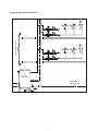
Large system wih recirculation
FROM BOOSTER
PUMP STATION
STORIES AT LOWER LEVELS
bar
CALEFFI
580 Series
bar
CALEFFI
580 Series
HOT WATER
PRODUCTION
bar
CALEFFI
580 Series
bar
CALEFFI
580 Series

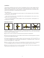
Installation conditions:
When installed upstream of a hot water tank, installing an expansion tank or similar is
recommended to absorb the increase in pressure due to the thermal expansion of the water.
When installing the 536 high range PRV as a first-stage pressure reduction valve, together with a
diaphragm type second-stage PRV, make the connection between the valves as short as
possible. High pressures can be generated by a temperature increase of the water trapped
between the valves. Caleffi offers a special spool fitting for this purpose, to fit the ½” to 1” valves.
For larger valves, connect MNPT x FNPT tailpieces.
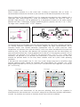
To minimize the risk of cavitation within the valve that erodes the valve seals, vibrations and noise,
the working conditions represented in the below diagram are highly recommended. Due to
numerous factors and variable conditions experienced such as system pressure, water
temperature, air presence, flow rate and velocity, which may affect the behavior of the pressure
reducing valve, the pressure ratio between the upstream pressure and the downstream set
pressure should be kept to 2:1 and no greater than a value of 3:1 (For example, upstream 145 psi
(1000 kPa), set pressure 73 psi (500 kPa), the pressure ratio = 145/73 = 2:1). Under these
conditions, the possible risk of cavitation and malfunction is minimized, however this does not
exclude the possible effects of the many other variables within the system under operating
conditions.
If the pressure ratio exceeds the 2:1 limit, the system design pressure or use of first stage
pressure reducing valves should be reviewed and reconsidered (For example, first stage
reducing pressure from 240 to 120 psi [1655 to 827 kPa] and then 2nd stage from 120 to 60 psi
[827 to 413 kPa]).
Piping upstream and downstream of the pressure reducing valve must be supported in
accordance with the manufacturer’s instructions, along with any other local authority requirements,
to avoid the creation and transfer of vibration and/or noise into the installation.
8
580 Series
1° stage
PRV
2° stage
PRV
possible
expansion possible
expansion
bar
bar
0
20
40
60
80
100
120
140
160
180
200
0 20 40 60 80 100 120 140 160 180
200
High risk of
cavitation
Normal operating
conditions
Out of normal
operating conditions
220
240
260
280
Upstream pressure (PSI)
Upstream pressure (kPa)
1200
1200
1600
800
400
Downstream pressure (PSI)
100
Downstream pressure (kPa)
200 400 800 1200
1
ST
stage
PRV
Cavitation diagram
0
20
40
60
80
100
120
140
160
180
200
0 20 40 60 80 100 120 140 160 180
200
High risk of
cavitation
Normal operating
conditions
Out of normal
operating conditions
220
240
260
280
Upstream pressure (PSI)
Upstream pressure (kPa)
1200
1200
1600
800
400
Downstream pressure (PSI)
100
Downstream pressure (kPa)
200 400 800 1200
2
ND
stage
PRV
Cavitation diagram
1st stage 2nd stage

The inlet strainer of the pressure reducing valve shall be periodically checked and cleaned, to
minimize any partial or complete blockage which may limit the flow rate from the valve and/or
create noise.
System flushing, cleaning and disinfection of the piping system in which the valve is installed shall
be performed only by qualified personnel in accordance with the system component manufacturer’s
instructions, along with any other applicable local authority requirements. Exceeding the maximum
stated chemical concentrations and/or duration of exposure may negatively impact the
performance of the system and/or components installed such as the pressure reducing valve.
Chemical dosed products must be chemically compatible with the pressure reducing valve
materials of construction, specified in this instruction sheet.
Installation below ground:
If installing the 536 Series PresCal HP pressure reducing valve underground, protect the valve
from becoming frozen in frost-prone areas. Allow sufficient space to remove the cartridge to
perform required maintenance. Reading the pressure gauge for setting purposes may be difficult
and an alternate means of checking downstream pressure may be necessary. Outdoor installation
is acceptable in regions where freezing does not occur.
Maintenance:
The pressure reducing valve must be checked and serviced in compliance with the provisions of
applicable regulations. Even when installed, commissioned and serviced properly, the pressure
reducing valve’s internal components are subject to normal wear and tear, which may result in
leaks and other malfunctioning. Check that it is in good working order and service and clean the
cartridge at least every 12 months.
For cleaning, inspection or replacement of the entire cartridge:
For cleaning, inspection or replacement of the entire cartridge:
1) Isolate the pressure reducing valve.
2) Unscrew the spring pressure regulating nut to release the spring tension.
3) Remove the cover.
4) Extract the cartridge using two screwdrivers.
5) After inspection and cleaning if necessary, the complete cartridge can be
re-installed or replaced using a spare cartridge.
6) Recalibrate the pressure reducing valve.
WARNING:
If it is critical to maintain the downstream pressure setting to protect the
plumbing system. As a safety measure, an expansion tank or safety relief
valve should be installed downstream of the pressure reducing valve.
8

10
Troubleshooting:
1. Increased downstream pressure near a water heater
This problem is due to the water being heated by the water heater. There is no relief of the
pressure because the pressure reducing valve is correctly closed. The solution is to install an
expansion vessel (between the heater and the reducer) to “absorb” the pressure increase or an
expansion control valve to relieve the pressure.
2. The pressure reducing valve does not maintain its set pressure
In most cases this is the result of impurities that deposit on the valve seat causing leakage with a
resulting increase in pressure downstream. The solution is to fit a filter upstream from the reducer
and subsequently to maintain and clean the cartridge (see Maintenance).
When installing the pressure reducing valve, make sure not to over-tighten the connections to the
valve, as, over time, a failure can occur with subsequent water leakage causing damage.
In the case of highly aggressive water, treat the water before it enters the pressure reducing valve,
in accordance with current legislation. Otherwise, the pressure reducing valve may be damaged
and not function correctly.
Safety
If the pressure reducing valve is not installed, commissioned and maintained
properly in accordance with these instructions, it may not operate correctly,
and may cause damage to objects and/or people. Make sure all the
connections are watertight.

11
NOTES

12
Caleffi North America, Inc.
3883 West Milwaukee Road
Milwaukee, WI 53208
T: 414.238.2360 F: 414.238.2366
10-2022
Caleffi shall not be liable for damages resulting from stress corrosion, misapplication or
misuse of its products.
Caleffi ne pourra etre tenue responsable des dommages resultant de la corrosion, d’une
mauvaise utilisation ou une mauvaise utilisation des produits.
05-2023
For Technical Support call 1-414-338-6338, or
email techsupport.us@calef.com
-
 1
1
-
 2
2
-
 3
3
-
 4
4
-
 5
5
-
 6
6
-
 7
7
-
 8
8
-
 9
9
-
 10
10
-
 11
11
-
 12
12


Caleffi H0008338 - PresCal HP High Range PRV Mode d'emploi
- Taper
- Mode d'emploi
dans d''autres langues
Documents connexes
-
Caleffi H0009464 - PresCal HP (Low Range) PRV Mode d'emploi
-
-
-
-
-
-
-
Caleffi North America 38476 Guide d'installation
-
-