
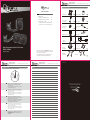
Quick User Guide
High Performance Liquid CPU Cooler
PB120 / PB240
1
98
Installation Guide
5. Connect power to the fan and water pump
1
3
5
7
9
11
2
4
6
8
10
12
13
Back plate x1
LGA 2011 screw x4
#6-32*6 screw x8
for radiator
Y-cable x1
for PB240 only
Gasket x4
for back plate
Stand-off Cylinder x4
Spring screw x4
Thermal grease x1
#6-32*29.5 screw x8
for fan
3 pin to 4 pin adapter x1
Insulating sheet x 1
INTEL Clip
(Pre-Installed) AMD Clip
5-1 水冷頭固定安裝完成後,將水冷導線端子插入相對應的CPU_OPT公
座上,需注意防呆限制。
5-2 風扇通電連接,將風扇導線端子插入相對應的CPU_FAN公座上,
需注意防呆限制。
5-1 Activate your water cooler by plugging the conducting wire
into the consistent CPU_OPT pin header and avoid
dummy-proof system.
5-2 To connect the fan, insert the fan cable to the CPU_FAN
socket and avoid dummy-proof.
5-1 Activez votre bloc refroidissement à eau en branchant le
câble d’alimentation dans la broche CPU_OPT et évitez le
système de détrompage.
5-2 Activez votre bloc refroidissement à eau en branchant le
câble d’alimentation dans la broche CPU_FAN et évitez le
système de détrompage.
5-1 Acktivieren Sie Ihren Wasserkühlung, indem Sie den
leitenden Draht in die zugehörige CPU_OPT stecken, und
vermeiden Sie das narrensichere System.
5-2 Acktivieren Sie Ihren Lüfter, indem Sie den leitenden Draht
in die zugehörige CPU_FAN Stiftleiste stecken, und
beachten Sie das narrensichere System.
5-1 Active la refrigeración por agua enchufando el cable de
conducción en la base de conexiones CPU_OPT consis-
tente y evite el sistema infalible.
5-2 Active el ventilador enchufando el cable de conducción en
la base de conexiones CPU_FAN consistente teniendo en
cuenta el sistema infalible.
Memo
• Product Overview
• Installation Guide
1. Install the fan and radiator in the case
2. Installation Instructions for LGA 2011
3. Install water block of AMD
4. Installation Instructions for AMD and INTEL
5. Connect power to the fan and water pump
Product Overview
Table of Contents
Technical Support Information
[email protected] 1-800-575-9885
----------------------------------------------------------------------------------
Thank you for purchasing a quality Rosewill product.
Please register your product at : www.rosewill.com
for complete warranty information and support for your product.
PB120 / PB240_A
EN
FR
DE
ES
CN
M3.5*31 screw x4
for back plate
High Performance
Liquid CPU Cooler
High Performance
Liquid CPU Cooler
High Performance
Liquid CPU Cooler
01
02
03
04
05
08
...............................................
...........
............
.............................
..
...
Thank you for purchasing a Rosewill Liquid CPU Cooler
Please read the instruction Manual before using and
retain it for your future reference.
The product images used are for illustration purposes
only and may vary from the product description.
Quick User GuidePB120 / PB240
Quick User GuidePB120 / PB240Quick User GuidePB120 / PB240

AMD INTEL
Quick User Guide
2
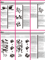
Installation Guide
1. Install the fan and radiator in the case
PB120 PB240
1-1 Secure the fan to the radiator with 4
#6-32*29.5mm screws.
1-2 Secure installed radiator in the case with 4
#6-32*6mm screws.
1-1 Fixez le ventilateur au radiateur à I’aide des 4
vis 6-32*29.5mm.
1-2 Fixez I’ensemble radiateur au boîtier à I’aide
des 4 vis 6-32*6mm.
1-1 Befestigen Sie den Lüfter mit 4 Schrauben
(6-32x29.5mm) am Kühlkörper.
1-2 Befestigen Sie den im Gehäuse installierten
Kühlkörper mit 4 Schrauben (6-32x6mm).
1-1 Fije el ventilador en el radiador con 4 tornillos
#6-32 de 29.5 mm.
1-2 Fije el radiador instalado en la carcasa con 4
tornillos #6-32 de 6 mm.
1-1 取4PCS #6-32*29.5mm風扇螺絲,將風扇固定在
水冷排上。
1-2 取4PCS #6-32*6mm水冷排螺絲將已裝好風扇的
水冷排固定在主機殼上。
1-1 Secure fans on radiator with 8 #6-32*29.5mm
screws.
1-2 Secure installed radiator in the case with 8
#6-32*6mm screws.
1-1 Fixez le ventilateur au radiateur à I’aide des 8 vis
6-32*29.5mm.
1-2 Fixez I’ensemble radiateur au boîtier à I’aide des
8 vis 6-32*6mm.
1-1 Befestigen Sie den Lüfter mit 8 Schrauben
(6-32x29.5mm) am Kühlkörper.
1-2 Befestigen Sie den im Gehäuse installierten
Kühlkörper mit 8 Schrauben (6-32x6mm).
1-1 Fije el ventilador en el radiadoer con 8 tornillos
#6-32 de 29.5 mm.
1-2 Fije el radiador instalado en la carcasa con 8
tornillos #6-32 de 6 mm.
1-1 取8PCS #6-32*29.5mm風扇螺絲,將風扇固定在水冷
排上。
1-2 取8PCS #6-32*6mm水冷排螺絲將已裝好風扇的水冷
排固定在主機殼上。
6-32*6
Radiator Screws
6-32*29.5
Fan Screws
6-32*29.5
Fan Screws
6-32*6
Radiator Screws
3
2. Installation Instructions for LGA 2011
2-1 Conrm the motherboard is LGA 2011 platform.
2-2 Secure 4 LGA 2011 screws into the correspond-
ing screw holes.
2-3 Apply a proper amount of the thermal grease on
CPU.
2-4 Tear the protector off from the bottom of water
block and place the installed water block steady
with buckle and LGA 2011 screws on the cut-out
of the motherboard.
2-5 Keep the copper bass plate touching the CPU as
much as possible and secure water block
temperately on top of LGA 2011 screws with 4.
4
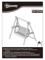
3. Install water block
of AMD
3-1 Find the correct AMD buckle as the gure shows.
3-2 Push buckle straight through the cut-out to
bottom without obligating securing.
3-1 Installation du bloc refroidissement à eau
pour un processeur AMD Trouvez la boucle
AMD appropriée comme illustré à la gure.
3-2 Insérez la boucle directement à travers
l’encadrement sans obligation de xation.
3-1 Suchen Sie wie in Abbildung gezeigt nach der
richtigen AMD-Klemme.
3-2 Drücken Sie die Klemme gerade durch die
Aussparung bis zur Unterseite; sie muss nicht
gesichert werden.
3-1 Encuentre el depósito de AMD correcto tal y
como muestra la gura.
3-2 Empuje el depósito sin torcerlo a través del
recorte hasta la parte inferior hasta que
quede jado.
3-1 確認主機板AMD型號選擇對應的扣具,按照上圖
安裝。
3-2 扣具無需螺絲固定,直接將扣具沿扣具卡槽推入到
底即可。
EN
FR
DE
ES
CN
EN
FR
DE
ES
CN
EN
2-1 Fixez les 4 vis du LGA 2011 dans les trous de vis
correspondants.
2-2 Insérez la boucle directement à travers l’encadre-
ment sans obligation de xation.
2-3 Mettez la quantité de graisse thermique
nécessaire sur le CPU.
2-4 Détachez le protecteur situé en bas du bloc
refroidissement à eau et le xer fermement avec
les vis de la boucle et du LGA 2011 sur l’encadre-
ment de la carte mère.
2-5 Maintenez la plaque de base en cuivre en contact
avec le CPU et xez le bloc refroidissement à eau
au-dessus du LGA 2011 avec les 4 vis à ressort.
FR
DE
EN
FR
DE
ES
CN
Buckle
cut-out
INTEL Clip
(Pre-installed)
Spring screws
CPU
LGA 2011
screws
Motherboard
High Performance Liquid CPU Cooler
PB120 / PB240
65 7
Quick User Guide
Installation Guide
4. Installation Instructions for AMD and INTEL
4-1 確認主機板型號選擇相對應的背板 (Back plate)
AMD/ INTEL面。
4-2 確認主機板的孔位,將4PCS螺杆(M3.5*31screws)
分別插入背板相對應的孔位需注意孔位與螺杆的防
呆卡位。
4-3 將插好螺杆的背板裝至主機板背面在主機板正面分
別裝入4PCS支柱 (Stand-off) 固定背板不掉落。
4-4 在CPU表面均勻塗抹適量的導熱膏。
4-5 將水冷頭銅底上的保護貼紙撕開,將裝好扣具的
水冷頭與已固定的螺杆相對應裝入,水冷頭保持
平放。
4-6 取4PCS彈簧螺母分別鎖至螺杆上固定水冷頭,確
保銅底貼緊CPU表面,彈簧螺母鎖入緊度適中。
4-1 Conrm the motherboard and match the correct
side of back plate (AMD/ INTEL).
4-2 Find the screw holes and secure 4 M3.5*31
screws in. kindly note the scramble of
dummy-proof between stand-off and M3.5*31
screws.
4-3 Insert the installed back plate on the back of the
motherboard and secure the stand-off from the
other side.
4-4 Apply a proper amount of the thermal grease on
CPU.
4-5 Tear the protector off from the bottom of the
water block and place the installed water block
steady with buckle and M3.5*31 screws on the
cut-out of motherboard.
4-6 Keep the copper bass plate touching the CPU as
much as possible and secure water block temperate-
ly on top of M3.5*31 screws with 4 spring screws.
4-1 Trouvez la carte mère et la plaque arrière AMD/
INTEL.
4-2 Trouvez les trous de vis et xez 4 vis M3.5*31
dans Veuillez respecter l’écart de détrompage et
la distance de sécurité des vis M3.5*31.
4-3 Insérez la plaque arrière installée au dos de la
carte mère et la xer de l’autre côté.
4-4 Mettez la quantité de graisse thermique
nécessaire sur le CPU.
4-5 Détachez le protecteur situé en bas du bloc
refroidissement à eau et le xer fermement avec
les vis de la boucle et du M3.5*31 sur l’encadre-
ment de la carte mère.
4-6 Maintenez la plaque de base en cuivre en contact
avec le CPU et xez le bloc refroidissment à eau
au-dessus du M3.5*31 avec les 4 vis à ressort.
4-1 Wählen Sie das richtige Motherboard und die
richtige Rückwand von AMD/ INTEL.
4-2 Suchen Sie nach den Schraubenlöchern und
drehen Sie 4 Schrauben (M3.5 x 31) hinein
Beachten Sie das narrensichere System zwischen
Abstandhalter und Schrauben (M3.5 x 31).
4-3 Stecken Sie die installierte Rückplatte an der
Rückseite des Motherboards hinein und
befestigen Sie Abstandhalter von der anderen
Seite.
4-1 Encuentre la placa base y la placa posterior
de AMD/ INTEL correctas.
4-2 Encuentre los oricios de los tornillos y je
los 4 tornillos M3.5*31. Tenga en cuenta la
separación entre el separador y los tornillos
M3.5*31.
4-3 Inserte la placa posterior instalada en la parte
posterior de la placa base y fije el separador
desde el otro lado.
4-4 Aplique una cantidad de grasa térmica
correcta en la CPU.
4-5 Quite el protector de la parte inferior del
bloque de agua y coloque el bloque de agua
instalado estable con el depósito y los tornillos
M3.5*31 en el recorte de la placa base.
4-6 Mantenga la placa de cobre tocando la PCU
tanto como sea posible y fije el bloque de
agua temporalmente en la parte superior de
los tornillos M3.5*31 con 4 tornillos con muelle.
EN
FR
DE
4-4 Tragen Sie eine geeignete Menge Wärmeleit-
paste auf die CPU auf.
4-5 Lösen Sie die Schutzfolie von der Unterseite
des Wasserblocks und platzieren Sie den
installierten Wasserblock mit der Klemme und
den Schrauben (M3.5 x 31) in der Aussparung
des Motherboards.
4-6 Achten Sie darauf, dass Kupfer-Mess-
ing-Platte und CPU möglichst in Kontakt
stehen; sichern Sie den Wasserblock
vorübergehend mit 4 Federschrauben auf der
Oberseite der Schrauben (M3.5 x 31).
DE
ES
CN
Dummy-proof
PB120 / PB240
High Performance Liquid CPU Cooler
2-1 Suchen Sie den richtigen LGA 2011-CPU-Kontakt
am Motherboard.
2-2 Befestigen Sie 4 LGA 2011-Schrauben in den
entsprechenden Schraubenlöchern.
2-3 Tragen Sie eine geeignete Menge Wärmeleitpaste
auf die CPU auf.
2-4 Quite el protector de la parte inferior del bloque
de agua y coloque el bloque de agua instalado
estable con el depósito y tornillos LGA 2011 en el
recorte de la placa base.
2-5 Mantenga la placa de cobre tocando la CPU
tanto como sea posible y je el bloque de agua
temporalmente en la parte superior de los
tornillos LGA 2011 con 4 tornillos.
2-1 Encuentre la place base LGA 2011 CPU PIN
correcta.
2-2 Fije los 4 tornillos LGA 2011 en los oricios de los
tornillos correspondientes.
2-3 Aplicar una cantidad de grasa térmica correcta en
la CPU.
2-4 Quite el protector de la parte inferior del bloque
de agua y coloque el bloque de agua instalado
estable con el depósito y tornillos LGA 2011 en el
recorte de la placa base.
2-5 Mantenga la placa de cobre tocando la CPU
tanto como sea posible y je el bloque de agua
temporalmente en la parte superior de los
tornillos LGA 2011 con 4 tornillos.
2-1 確認主機板為LGA 2011平臺。
2-2 將4PCS雙頭螺絲 (LGA 2011 screws) 分別裝入對應螺
絲孔位。
2-3 在CPU表面均勻塗抹適量的導熱膏。
2-4 將水冷頭銅底上的保護貼紙撕開,將裝好扣具的水冷頭
與已固定的雙頭螺絲相對應裝入,水冷頭保持平放。
2-5 取4PCS彈簧螺母 (Spring screws) 分別鎖至雙頭螺絲上
固定水冷頭,確保銅底貼緊CPU表面,彈簧螺母鎖入緊
度適中。
ES
CN
Dummy-proof
Spring screw
AMD clip
Stand-off cylinder
CPU
Motherboard
Insulating sheet
Backplate gasket
Back plate in AMD side
Back plate screw
Spring screw
INTEL clip
Stand-off cylinder
CPU
Motherboard
Backplate gasket
Back plate in INTEL side
Back plate screw
Buckle
cut-out
AMD Clip
折線
-
 1
1
-
 2
2


Rosewill PB120 CPU Liquid Cooler Manuel utilisateur
- Taper
- Manuel utilisateur
- Ce manuel convient également à
dans d''autres langues
Autres documents
-
 Outsunny 84A-282V00ND Assembly Instructions
-
Hummer H-240AURA Manuel utilisateur
-
PawHut D02-100V01GY Assembly Instructions
-
-
SilverStone HE02 Le manuel du propriétaire
-
Akasa Venom A10 Manuel utilisateur
-
-
Corsair HYDRO Series H100i RGB PLATINUM SE Extreme Performance 240mm RGB Liquid CPU Cooler Manuel utilisateur
-
Corsair Hydro Series Guide de démarrage rapide
-
