Milwaukee T-TEC 201 Instructions For Use Manual
- Catégorie
- Marteaux rotatifs
- Taper
- Instructions For Use Manual

GB
D
F
I
E
P
NL
DK
S
FIN
TR
T-TEC 201
Instructions for use
Please read and save these
instructions.
Gebrauchsanleitung
Bitte lesen und aufbewahren.
Instruction d’utilisation
Prière de lire et de conserver.
Istruzioni d’uso
Si prega di leggere le istruzioni e
di conservarle.
Instrucciones de uso
Lea y conserve estas
instrucciones por favor.
Instruções de serviço
Por favor leia e conserve em seu
poder.
Gebruiksaanwijzing
Lees en let goed op deze
adviezen.
Brugsanvisning
Vær venlig at læse og opbevare.
Bruksanvisning
Var god läs och tag tillvara dessa
instruktioner.
Käyttöohje
Lue ja säilytö
Kullanøm kølavuzu
Lütfen okuyun ve saklayin
1
2
1
2
G
R
I
P
Z
U
A
F
U

1
ENGLISH
T-TEC 201
You have high standards and expect to purchase quality goods – quality offered by
Milwaukee.
We have built a durable and reliable electric power tool for you.
Please read the instructions for use before first operation so you can handle your
power tool effectively and safely.
We are sure that buying an Electric Power Tool from Milwaukee was the right choice!
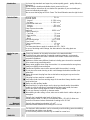
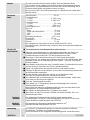
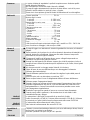
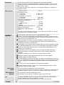
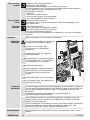
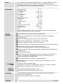
Nominal power 750 W. . . . . . . . . . . . . . . . . . . . .
No-load speed
1st gear 0–1200 min
-1
. . . . . . . . . . . . . . . . . . . . . .
2nd gear 0–3400 min
-1
. . . . . . . . . . . . . . . . . . . . . .
Speed under load max.
1st gear 750 min
-1
. . . . . . . . . . . . . . . . . . . . . . . . .
2nd gear 2200 min
-1
. . . . . . . . . . . . . . . . . . . . . . . .
Rate of percussion under
load max. 36000 min
-1
. . . . . . . . . . . . . . . . . . . . . . .
Drilling capacity in
Concrete 20 mm. . . . . . . . . . . . . . . . . . . . . . . . . .
Brick and tile 22 mm. . . . . . . . . . . . . . . . . . . . . .
Steel 13 mm. . . . . . . . . . . . . . . . . . . . . . . . . . . . .
Wood 40 mm. . . . . . . . . . . . . . . . . . . . . . . . . . . .
Drill opening range 1,5-13 mm. . . . . . . . . . . . . . .
Drive shank 1/2”x20. . . . . . . . . . . . . . . . . . . . .
Chuck neck diameter 43 mm. . . . . . . . . . . . . . . .
Weight 2,1 kg. . . . . . . . . . . . . . . . . . . . . . . . . . . .
The data stated above apply for models with 230 – 240 V.
In case of deviating mains voltage, the data stated on the rating plate are
applicable.
Please pay attention to the safety instructions in the attached leaflet!
Dust that arises when working on material containing asbestos or stonework
containing crystalline silicic acid is harmful to the health. Please follow accident
prevention regulations.
Appliances used at many different locations including open air must be connected
via a current surge preventing switch.
Always wear goggles when using the machine. It is recommended to wear gloves,
sturdy non slipping shoes and apron.
Sawdust and splinters must not be removed while the machine is running.
Do not pierce the motor housing as this could damage the double insulation (use
adhesives).
Always disconnect the plug from the socket before carrying out any work on the
machine.
Only plug-in when machine is switched off.
Keep mains lead clear from working range of the machine. Always lead the cable
away behind you.
Always use the auxiliary handle.
When working in 1st gear always use the bow–type handle and/or the auxialiar
handle. In case the machine is operated with the bow–type handle, the lower
area of the motor housing might be used as auxiliary handle.
Do not use diamond core drills on hammer mode.
When drilling in walls ceiling, or floor, take care to avoid electric cables and gas or
waterpipes.
Typically the A-weighted noise levels of the tool are:
Sound pressure level = 97 dB (A). Sound power level = 110 dB (A). Wear ear
protectors! Measured values determined according to EN 50 144.
Typically the weighted acceleration is 9 m/s
2
.
Measured values determined according to EN 50 144.
The electronic drill/screwdriver can be universally used for drilling, percussion drilling,
screwdriving and cutting screw threads.
Do not use this product in another way as stated for normal use.
Introduction
Technical Data
Advice for your
safety
Measured sound
value
Measured
vibration value
Use

2
ENGLISH
T-TEC 201
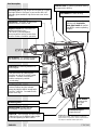
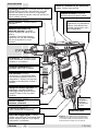
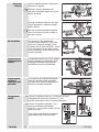
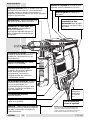
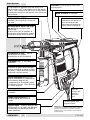
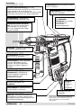
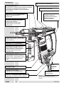
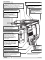
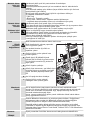
Brief description
1
2
1
2
G
R
I
P
ZU
A
F
U
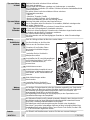
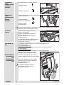
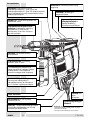
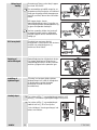
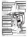
Lock button for switch locking
Modifications: Text, diagrams and data are correct
at the time of printing. In the interest of continuous
improvement of our products, technical specifications
are subject to alteration without prior notice.
Ergonomically shaped
housing with removable
bow–type handle for perfect
handling in various operating
ranges.
Reversing lever
Spindle-lok – automatic locking of the
spindle when the motor is idle.
Planetary gear for high torque at low speed in 1st gear
and high speed in 2nd gear. In percussion drills, the
planetary gear enables a high stroke rate even at low
speed.
Gear lever for switching between 1st
and 2nd gear.
Selector lever for switching between drilling
and percussion drilling.
Keyless chuck with steelsleeve for
tightening without a key.
The chuck is secured against
loosening with a locking screw when
used in counter–clockwise operation.
Two switch lever for switching the
machine on and off from both handle
positions. The built–in electronics
enable continuously variable
“accelerating”.
Quik–Lok – fast exchange of power supply
cables for the use of different cable lengths
or for fast replacing of defect cables.
Service cover for easy and fast
exchanging of carbon brushes.
Attachment eye for
supporting loop
Push–button
to remove the
bow–type
handle
Bit reception – it is possible to fit drill
bits directly into the working spindle.
Auxiliary handle can be rotated to
various positions and has a depth
gauge and built-in drill-bit storage with
room for 3 drill-bits, 3 screwdriver bits,
and a chuck key.

3
ENGLISH
T-TEC 201
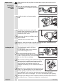
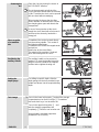
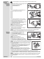
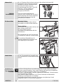
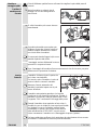
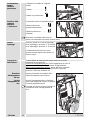
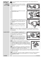
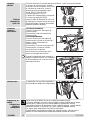
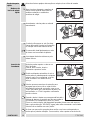
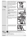
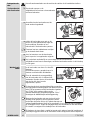
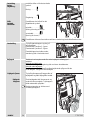
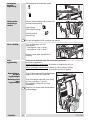
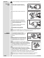
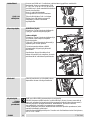
Always disconnect the plug from the socket before carrying out any work on the
machine.
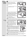
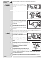
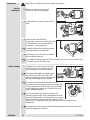
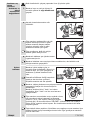
1. Open the chuck and loosen the locking
screw with aid of a screwdriver by turning
it clockwise.
2. Usually, the chuck can be removed by
hand.
3. Should the chuck be stuck on the drill
spindle, fit two fork wrenches to the chuck
and the drill spindle (see illustration) or fix
an Allen key in the chuck.
If necessary, hit the key shaft lightly with a
plastic hammer.
4. Mount the chuck in reverse order.
Aways re–fasten the locking screw after mounting the chuck. Otherwise thchuck
might become loose in anti–clockwise operation.
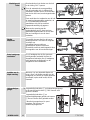
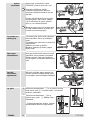
The chuck can be used for drill bits or
screwdriver bits.
For this purpose, Open chuck, insert the
selected bit and tighten chuck.
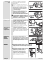
Due to the automatic spindle lock the
chuck cannot be turned when the machine
is idle. Therefore the chuck can be opened
with one hand without steadying.
The chuck has chucking power retention to ensure that
the inserted tool cannot become loose when drilling.
When the chuck is tensioned an audible ”Clack”
signals that the chucking power retention has
engaged, the following ”Clicks” confirm tensioning of
the tool.
When the chuck is opened with a strong jerk as far as
it will go, it is possible that it can’t be closed anymore.
Instead, ”grating” can be felt (as if the chuck were
over–tightened). In this case turn the sleeve once more in the ”RELEASE”
direction; now it can be closed again. The chuck is not damaged by this ”grating”.
When percussion drilling in stone the drill bit should be checked for tight seat in the
chuck after first use. If necessary, re–tighten the chuck by hand.
Keyless chuck
Changing the
keyless drill
chuck
Inserting the tool
G
R
I
P
ZU
A
F
U
G
R
I
P
ZU
A
F
U
G
R
I
P
ZU
A
F
U
G
R
I
P
ZU
A
F
U
c
l
a
c
k
c
l
i
c
k
c
l
i
c
k
c
l
i
c
k

4
ENGLISH
T-TEC 201
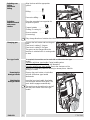
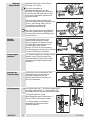
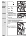
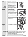
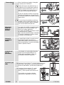
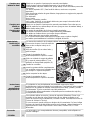
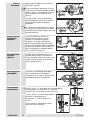
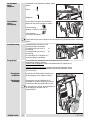
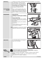
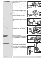
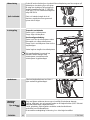
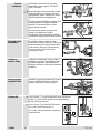
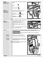
Open the chuck by turning the sleeve in
the ”RELEASE” direction.
Due to the automatic spindle lock the
chuck cannot be turned when the machine
is idle. Therefore the chuck can be opened
with one hand without steadying.
When turning the sleeve the chucking
power retention is released, after 1/4 turn
the clamping jaws open and release the
clamped tool.
In case of strong tension at the chuck
steady the chuck head with a fork wrench
and loosen the sleeve by hand with a
strong jerk.
Screwdriver bits can be inserted directly
into the working spindle. This results in
the following advantages:
Screwdriver bits can be exchanged easier
and quicker.
Better view at the screw fitting.
The weight of the machine is reduced
when not working with the chuck.
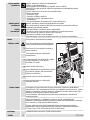
The auxiliary handle can be moved as
required. To move the handle loosen the
wing nut, turn the handle to the required
position and re–tighten the wing nut.
For drilling to specific depth, slide the
depth gauge into the hole provided in the
handle and fasten it at the required drilling
depth.
1. Press in the lower locking tabs and pull the storage
compartment out as far as it will go . Screwdriver
bits* and chuck keys* can be taken out.
2. Press in the upper locking tabs and
take the storage compartment out
completely . Drill bits* can be taken out.
*Not included in standard equipment,
available as an accessory.
Removing the
tool
Direct reception
of screwdriver
bits
Positioning the
auxiliary handle
Setting the
depth gauge
Tool storage
G
R
I
P
ZU
A
F
U
G
R
I
P
ZU
A
F
U
G
R
I
P
ZU
A
F
U
1
2
1
2
G
R
I
P
ZU
A
F
U
1
2
1
2
G
R
I
P
ZU
A
F
U
2
1
4
3

5
ENGLISH
T-TEC 201
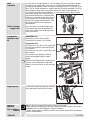
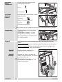
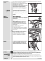
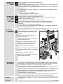
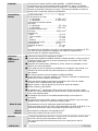
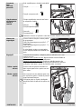
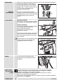
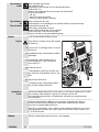
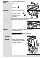
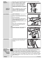
Align the lever with the appropriate
symbol:
Drilling:
. . . . . . . . . . . . . .
Percussion drilling:
. . . .
Place the reversing lever opposite the
respective symbol:
Forward rotation
. . . . . . . .
(Drilling / Screwing in)
Reverse rotation:
. . . . . . .
(Unscrewing)
Only change direction of rotation when the machine has stopped.
Depress the lock button and turn the gear
lever.
Gear lever in setting 1: 1st gear
Gear lever in setting 2: 2nd gear
The gears can be changed when the
machine is switched off or is running under
no load.
As required, the machine can be used with or without the bow–type
handle.
Operation with bow–type handle:
Easier handling when
hammer–drilling or in case of large drill diameters.
Operation without bow–type handle:
Due to the shortness of the
machine it is especially suited for working in narrow places. Ideal for
driving–in screws.
Depress the push–button on both sides
and pull off the bow–type handle
downwards.
Insert the bow–type handle from below
into the upper and the lower guide. The
push–button engages automatically.
The machine can be switched on and off
with the push–button in the bow–type
handle.
Switching over
drilling
percussion
drilling
Switching
between forward
and reverse
rotation
Changing gear
Bow-type handle
Removing the
bow-type handle
Attaching the
bow-type handle
1
2
1
2
1
2
1
2
G
R
I
P
Z
U
A
F
U
1
2
1
2

6
ENGLISH
T-TEC 201
Connect only to a single-phase AC current supply and only to the mains voltage
specified on the rating plate. Connection to sockets without earth protection is
possible as the appliance features protective insulation to DIN 57 740/ VDE 0740
and CEE 20. Radio suppression complies with the European standard EN 55014.
When fitting the plug, make sure that the brown (live) wire of this appliance is
connected to the plug terminal marked L or coloured red, and the blue (neutral)
wire of this appliance is connected to the
plug terminal marked N or coloured black.
Under no circumstances must the wires of
this appliance be connected to the earth
terminal of the plug marked either E, with
the earth symbol or coloured green or
green/yellow.
Insert the Quik–Lok power supply cable
such that the lug of the plug grasps the
relief of the socket. After inserting lock by
turning clockwise.
Intermittent use
Switching on: Press On-/off switch
Switching off: Release On-/off switch
Continuous use
Switching on: Press the On-/off switch and
then the locking button, after that release
on-off switch.
Switching off: Press the On-/off switch and
then release.
The speed can be infinitely varied by
slowly releasing/pressing the switch
trigger.
When the bow-type handle is mounted, the
machine can be switched on with either
buttons: on the housing or on the bow-type
handle.
A commercial supporting loop can be fixed
in the attachment eye below the handle.
Take the drill out of the hole from time to time to remove dust.
Switch to percussion-drilling for concrete, hard bricks and tiles, stone, hard cement,
and marble (but not when drilling the surface of marble).
For tiles, paving-stones, soft bricks and tiles, soft cement, breeze-block and plaster,
switch to normal drilling.
Mains
connection
Quik–Lok power
supply cable
Switching the
machine on and
off
Supporting loop
Advice for
operation
Tips on drilling in
masonry
1
2
1
2
G
R
I
P
ZU
A
F
U
1
2
1
2
G
R
I
P
ZU
A
F
U

7
ENGLISH
T-TEC 201
Use percussion carbide tipped masonry drill-bits.
When drilling a hard, smooth surface (e.g. tiles), cover the point to be drilled with
adhesive tape in order to prevent the drill tip from skidding.
Center punch the point you have marked for drilling.
Always hold sheet metal firmly in a vice.
Lay a block of wood under thin metal to prevent it from distorting.
Use HSS spiral drill bits. (For white cast iron, use drill bits with special tips.)
Before drilling large-diameter holes, first drill a small pilot hole.
Use lubricant:
Steel: Oil
Aluminium: Turpentine, paraffin
Brass, copper, cast iron: no lubricant, but take the drill out of the hole frequently to
cool it off.
Center punch the point you have marked for drilling. To prevent the wood from
splintering when the drill bit tip breaks through, lay a piece of scrap wood underneath
it, or drill from both sides.The maximum drill-diameter can only be reached with a
Forstner–drill bit.
Use screwdriver bits of the appropriate size and shape.
Suitable screws can be driven into softwood without pre-drilling.
Pre-drill into hardwood or for screws of large diameter.
Pre-drill further for countersunk screws.
For woodscrews threaded less than their full length, pre-drill approx. half the length
of the screw.
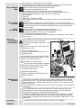
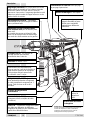
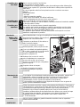
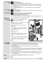
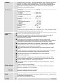
The ventilation slots of the machine must be kept clear at all times.
Always disconnect the plug from the
socket before carrying out any work on the
machine.
1. Loosen the screws (A) on both sides and
remove the covers.
2. Set the turnover switch
right–handed/left–handed rotation to the
middle position.
3. Carefully bend the plastic bracket (B) and
pull out the carbon brush holder (C) with
aid of a small screwdriver (D).
4. Exchange the carbon brushes.
5. Insert the carbon brush holders completely
with new carbon brushes into the holder
until the plastic brackets engage.
6. Re-fasten both covers.
7. Set the turnover switch
right–handed/left–handed rotation to the
required position.
If the machine is mainly used for percussion drilling, regularly remove collected
dust from the chuck. To remove the dust hold the machine with the chuck facing
down vertically, and completely open and close the chuck. The collected dust will
fall from the chuck.
It is recommended to regularly use cleaner for the clamping jaws and the clamping
jaw borings.
Use only Milwaukee accessories and spare parts. Should components need to be
exchanged which have not been described, please contact one of our Milwaukee
service agents (see our list of guarantee/service addresses).
If needed, an exploded view of the tool can be ordered. Please state the ten–digit No.
as well as the machine type printed on the label and order the drawing at your local
service agents or directly at: Atlas Copco Electric Tools GmbH, Postfach 320, D–71361
Winnenden.
The range of accessories with part numbers is shown in our catalogue.
Tips on drilling in
metal
Tips on drilling
into wood
Tips for
screw-driving
Maintenance
Exchanging the
carbon brushes
Maintenance of
the chuck
Accessories
B
C
D
A
A

8
DEUTSCH
T-TEC 201
Sie sind anspruchsvoll und erwarten Qualität, die Ihnen Milwaukee bietet.
Für Sie haben wir ein haltbares und möglichst sicheres Elektrowerkzeug gebaut.
Bitte lesen Sie vor Inbetriebnahme Ihres Gerätes die Gebrauchsanleitung, um Ihr
Elektrowerkzeug effektiv und gefahrlos nutzen zu können.
Wir sind sicher, daß Sie mit Elektrowerkzeugen von Milwaukee Ihre richtige Wahl
getroffen haben.
Nennaufnahme 750 W. . . . . . . . . . . . . . . . . . . .
Leerlaufdrehzahl
1. Gang 0–1200 min
-1
. . . . . . . . . . . . . . . . . . . . . . .
2. Gang 0–3400 min
-1
. . . . . . . . . . . . . . . . . . . . . . .
Lastdrehzahl max.
1. Gang 750 min
-1
. . . . . . . . . . . . . . . . . . . . . . . . . .
2. Gang 2200 min
-1
. . . . . . . . . . . . . . . . . . . . . . . . .
Lastschlagzahl max. 36000 min
-1
. . . . . . . . . . . . . .
Bohr-ø in
Beton 20 mm. . . . . . . . . . . . . . . . . . . . . . . . . . . .
Ziegel und Kalksandstein 22 mm. . . . . . . . . . .
Stahl 13 mm. . . . . . . . . . . . . . . . . . . . . . . . . . . . .
Holz 40 mm. . . . . . . . . . . . . . . . . . . . . . . . . . . . . .
Bohrfutterspannbereich 1,5-13 mm. . . . . . . . . . .
Bohrspindel 1/2”x20. . . . . . . . . . . . . . . . . . . . .
Spannhals-ø 43 mm. . . . . . . . . . . . . . . . . . . . . . . .
Gewicht 2,1 kg. . . . . . . . . . . . . . . . . . . . . . . . . . .
Die angegebenen Daten gelten für eine Ausführung mit 230–240 V.
Bei Abweichung der Netzspannung sind die auf dem Leistungsschild aufgeführten
Daten gültig.
Sicherheitshinweise der beiliegenden Broschüre beachten!
Staub der bei der Bearbeitung von asbesthaltigen Materialien und Gestein mit
kristalliner Kieselsäure entsteht, ist gesundheitsschädlich. Beachten Sie die
Unfallverhütungsvorschriften VBG 119 der Berufsgenossenschaft.
Steckdosen in Außenbereichen müssen mit Fehlerstrom-Schutzschaltern
ausgerüstet sein. Das verlangt die Installationsvorschrift für Ihre Elektroanlage. Bitte
beachten Sie das bei der Verwendung unseres Gerätes – sprechen Sie mit Ihrem
Elektroinstallateur.
Beim Arbeiten mit der Maschine stets Schutzbrille tragen. Schutzhandschuhe, festes
und rutschsicheres Schuhwerk und Schürze werden empfohlen.
Späne oder Splitter dürfen bei laufender Maschine nicht entfernt werden.
Gehäuse der Maschine nicht anbohren, da sonst die Schutzisolierung unterbrochen
wird (Klebeschilder verwenden).
Vor allen Arbeiten an der Maschine Stecker aus der Steckdose ziehen.
Maschine nur ausgeschaltet an die Steckdose anschließen.
Anschlußkabel stets vom Wirkungsbereich der Maschine fernhalten. Kabel immer
nach hinten von der Maschine wegführen.
Stets den Zusatzhandgriff verwenden.
Beim Arbeiten im 1. Getriebegang immer den Bügelhandgriff und / oder den
Zusatzhandgriff verwenden.
Beim Einsatz der Maschine mit Bügelhandgriff kann auch der untere Bereich des
Motorgehäuses als Zusatzhandgriff benutzt werden.
Bei Arbeiten mit Diamantbohrkronen Schlagwerk ausschalten.
Beim Bohren in Wand, Decke oder Fußboden auf elektrische Kabel, Gas- und
Wasserleitungen achten.
Der A-bewertete Geräuschpegel des Gerätes beträgt typischerweise:
Schalldruckpegel = 97 dB (A). Schalleistungspegel = 110 dB (A). Gehörschutz
tragen! Meßwerte ermittelt entsprechend EN 50 144.
Die bewertete Beschleunigung beträgt typischerweise 9 m/s
2
.
Meßwerte ermittelt entsprechend EN 50 144.
Der Elektronik-Schlagbohrer/Schrauber ist universell einsetzbar zum Bohren,
Schlagbohren, Schrauben und Gewindeschneiden.
Dieses Gerät darf nur wie angegeben bestimmungsgemäß verwendet werden.
Vorwort
Technische
Daten
Hinweise für
Ihre Sicherheit
Geräusch-
meßwerte
Vibrations-
meßwerte
Verwendung

9
DEUTSCH
T-TEC 201
Kurzbeschreibung
1
2
1
2
G
R
I
P
ZU
A
F
U
Arretierknopf zum Feststellen des
Schalterdrückers.
Änderungen: Text, Bild und Daten entsprechen dem
technischen Stand zur Zeit des Drucktermins.
Änderungen im Sinne der Weiterentwicklung unserer
Produkte sind vorbehalten.
Ergonomisch geformtes
Gehäuse mit abnehmbarem
Bügelgriff für optimale
Handhabung in
verschiedenen
Einsatzbereichen.
Umschalter Rechts-Linkslauf
FIXTEC – Automatische Spindelarretierung
bei stillstehendem Motor.
Planetengetriebe für hohes Drehmoment bei geringer
Drehzahl im 1. Gang und hoher Drehzahl im 2. Gang.
Bei Schlagbohrmaschinen sorgt das Planetengetriebe
bereits bei geringer Drehzahl für eine hohe Schlagzahl.
Schalthebel zum Umschalten
zwischen 1. Gang und 2. Gang.
Schalthebel zum Umschalten zwischen
Bohren und Schlagbohren.
Schnellspannbohrfutter mit
Stahlhülse für werkzeugloses
Spannen.
Das Bohrfutter ist mit einer
Sicherungsschraube gegen Lösen bei
Linkslauf gesichert.
Zwei Schalterdrücker zum Ein- und
Ausschalten der Maschine von beiden
Griffpositionen aus.Die eingebaute
Elektronik ermöglicht ein stufenloses
”Gasgeben”.
Quik-Lok – Kabelschnellwechselsystem
zum Einsatz unterschiedlicher Kabellängen
bzw. zum schnellen Ersatz defekter Kabel.
Servicedeckel für einfachen und
schnellen Kohlebürstenwechsel.
Anhängeöse für
Handschlaufe
Drücker zum
Entfernen des
Bügelgriffs
Bitdirektaufnahme – Schrauberbits
können direkt in die Bohrspindel
eingesetzt werden.
Verstellbarer MF-Handgriff mit
Tiefenanschlag und integrierter
Werkzeuggarage. In der
Werkzeuggarage können 3 Bohrer, 3
Schrauberbits und der
Bohrfutterschlüssel untergebracht
werden.

10
DEUTSCH
T-TEC 201
Vor allen Arbeiten an der Maschine Stecker aus der Steckdose ziehen.
1. Bohrfutter öffnen und Sicherungsschraube
mit einem Schraubendreher
rechtsdrehend lösen.
2. Im Normalfall kann das Bohrfutter von
Hand abgeschraubt werden.
3. Sollte das Bohrfutter sehr fest auf der
Bohrspindel sitzen, zwei Gabelschlüssel
an den Schlüsselflächen des
Bohrfutterkopfs und der Spindel ansetzen
oder einen Inbusschlüssel in das
Bohrfutter einspannen.
Gegebenenfalls sind leichte Schläge mit
einem Gummihammer auf den
Schlüsselschaft erforderlich.
4. Die Montage des Bohrfutters erfolgt in
umgekehrter Reihenfolge.
Nach der Montage des Bohrfutters die Sicherungsschraube unbedingt wieder
befestigen, da sich das Bohrfutter sonst im Linkslauf lösen kann.
In das Bohrfutter sind Bohrer oder
Schrauberbits einsetzbar.
Dazu Bohrfutter öffnen, Werkzeug
einsetzen und Schnellspannbohrfutter von
Hand spannen.
Durch die automatische
Spindelarretierung kann sich das
Bohrfutter im Stillstand nicht verdrehen.
Somit kann das Bohrfutter mit nur einer
Hand ohne Gegenhalten geöffnet und gespannt werden.
Das Bohrfutter besitzt eine Spannkraftsicherung, damit
sich das eingespannte Werkzeug während der Arbeit
nicht lösen kann.
Beim Spannen des Bohrfutters signalisiert ein “Clack”
das Einrasten der Spannkraftsicherung, die darauf
folgenden “Clicks” bestätigen die eigentliche
Werkzeugspannung.
Wenn das Bohrfutter mit einem starken Ruck bis
Anschlag geöffnet wird, läßt es sich unter Umständen
nicht mehr schließen und es ist statt dessen ein
“Ratschen”spürbar (als wenn es überdreht wäre). In diesem Falle die Hülse
nochmals gegen Anschlag in Richtung “AUF” drehen; das Bohrfutter läßt sich nun
wieder schließen. Ein Defekt am Bohrfutter entsteht durch dieses “Ratschen” nicht.
Bei Schlagbohren in Gestein sollte nach der ersten Bohrung der Bohrer auf festen
Sitz im Bohrfutter überprüft werden. Gegebenenfalls das Bohrfutter von Hand
nachspannen.
Schnellspann-
bohrfutter
Schnellspann-
bohrfutter
wechseln
Werkzeug
einsetzen
G
R
I
P
ZU
A
F
U
G
R
I
P
ZU
A
F
U
G
R
I
P
ZU
A
F
U
G
R
I
P
ZU
A
F
U
c
l
a
c
k
c
l
i
c
k
c
l
i
c
k
c
l
i
c
k

11
DEUTSCH
T-TEC 201
Bohrfutter durch Drehen der Hülse in
Richtung “AUF” öffnen.
Durch die automatische
Spindelarretierung kann sich das
Bohrfutter im Stillstand nicht verdrehen.
Somit kann das Bohrfutter mit nur einer
Hand ohne Gegenhalten geöffnet und
gespannt werden.
Zuerst wird durch das Verdrehen der
Hülse die Spannkraftsicherung gelöst, erst
nach ca 1/4 Drehung öffnen sich die
Spannbacken und geben das
eingespannte Werkzeug frei.
Bei starker Spannung am Bohrfutterkopf
mit einem Gabelschlüssel gegenhalten
und dann Hülse mit einem kräftigen Ruck
von Hand lösen.
Schrauberbits können direkt in die
Arbeitsspindel eingesetzt werden.
Daraus ergeben sich folgende Vorteile:
Schrauberbits können einfacher und
schneller gewechselt werden.
Bessere Sicht auf die Verschraubung.
Das Arbeitsgewicht der Maschine veringert
sich durch Wegfall des Bohrfutters.
Der Zusatzhandgriff kann beliebig verdreht
werden; hierzu Flügelschraube lösen,
Zusatzhandgriff in gewünschte Position
verdrehen und Flügelschraube wieder
festziehen.
Zum Bohren auf eine bestimmte Tiefe
Tiefenanschlag in die Bohrung am
Handgriff schieben und um die
gewünschte Bohrtiefe (versetzt zum
Bohrer) festklemmen.
1. Verriegelung drücken und Werkzeuggarage bis
Anschlag herausziehen . Schrauberbits* und
Bohrfutterschlüssel* können entnommen werden.
2. Verriegelung drücken und
Werkzeuggarage ganz herausziehen .
Bohrer* können entnommen werden.
* Im Lieferumfang nicht enthalten,
empfohlene Ergänzung aus dem
Zubehörprogramm.
Werkzeug
herausnehmen
Bitdirekt-
aufnahme
Zusatzhandgriff
verdrehen
Einstellen des
Tiefenanschlags
Werkzeuggarage
G
R
I
P
ZU
A
F
U
G
R
I
P
ZU
A
F
U
G
R
I
P
ZU
A
F
U
1
2
1
2
G
R
I
P
ZU
A
F
U
1
2
1
2
G
R
I
P
ZU
A
F
U
2
1
4
3

12
DEUTSCH
T-TEC 201
Schaltschieber dem entsprechenden
Symbol gegenüberstellen:
Bohren:
. . . . . .
Schlagbohren:
Umschalter dem entsprechenden Symbol
gegenüberstellen:
Rechtslauf
. . . . . . .
(Bohren / Schraube eindrehen)
Linkslauf:
. . . . . . . .
(Schraube herausdrehen)
Umschalter erst nach Auslauf der Maschine (bei stillstehendem Motor) betätigen.
Sperrknopf drücken und Gangschalter
verdrehen.
Gangschalter in Stellung 1: 1. Gang
Gangschalter in Stellung 2: 2. Gang
Die Gangschaltung ist im Stillstand oder
im Leerlauf schaltbar.
Die Maschine kann je nach Anwendung mit oder ohne Bügelgriff eingesetzt
werden.
Einsatz mit Bügelgriff:
Bessere Handhabung beim Schlagbohren oder bei großen
Bohrdurchmessern.
Einsatz ohne Bügelgriff:
Wegen der kurzen Baulänge besonders geeignet zum
Arbeiten in engen Lagen. Ideal zum Schrauben.
Drücker beidseitig eindrücken und
Bügelgriff nach unten abziehen.
Bügelgriff von unten in die obere und
untere Führung einschieben. Der Drücker
rastet automatisch ein.
Die Maschine kann mit dem
Schalterdrücker im Bügelgriff ein- und
ausgeschaltet werden.
Umschalten:
Bohren
Schlagbohren
Umschalten:
Rechtslauf
Linkslauf
Gangschaltung
Bügelgriff
Bügelgriff
entfernen
Bügelgriff
befestigen
1
2
1
2
1
2
1
2
G
R
I
P
Z
U
A
F
U
1
2
1
2

13
DEUTSCH
T-TEC 201
Nur an Einphasen-Wechselstrom und nur an die auf dem Leistungsschild
angegebene Netzspannung anschließen.
Anschluß ist auch an Steckdosen ohne
Schutzkontakt möglich, da eine
Schutzisolierung nach DIN 57 740/ VDE
0740 bzw. CEE 20 vorliegt. Die
Funkentstörung entspricht der
Europanorm EN 55014.
Die Quik-Lok-Anschlußleitung so
einsetzen, daß die Nasen des Steckers in
die Aussparungen der Buchse eingreifen.
Nach dem Einstecken Verriegelung
rechtsdrehend schließen.
Momentschaltung
Einschalten: Ein-/Ausschalter drücken.
Ausschalten: Ein-/Ausschalter loslassen.
Dauerschaltung
Einschalten: Ein-/Ausschalter drücken und
dann Arretierknopf drücken,
Ein-/Ausschalter loslassen.
Ausschalten: Ein-/Ausschalter drücken
und loslassen.
Die Drehzahl kann je nach Druck auf den
Schalterdrücker stufenlos verstellt werden.
Bei montiertem Bügelgriff kann die
Maschine wahlweise am Gehäuse oder
am Bügelgriff geschaltet werden.
An der Öse unterhalb des Handgriffs kann
eine handelsübliche Handschlaufe befestigt
werden.
Von Zeit zu Zeit den Bohrer aus der Bohrung ziehen um den Staub zu beseitigen.
Bei Beton, hartem Ziegelstein, Stein, hartem Zement und Marmor auf Schlagbohren
schalten (Anbohren von Marmor jedoch ohne Schlagbohren)
Bei Fliesen, Fußbodenplatten, weichen Ziegelsteinen, Zementkalk, Schlackensteinen
und Putz auf Bohren schalten.
Beim Anbohren glatter Oberflächen (z.B. Fliesen) Bohrstelle mit Klebestreifen
bekleben um ein Abrutschen zu vermeiden.
Hartmetallbestückte Bohrer verwenden. Nur Bohrer mit zylindrischen Schaft
einspannen, keine SDS-Plus Bohrer einspannen!
Netzanschluß
Quik-Lok
Anschlußleitung
Ein-/Ausschalten
Handschlaufe
Arbeitshinweise
Tips zum Bohren
in Gestein
1
2
1
2
G
R
I
P
ZU
A
F
U
1
2
1
2
G
R
I
P
ZU
A
F
U

14
DEUTSCH
T-TEC 201
Markierte Bohrstelle mit einem Körner ankörnen.
Blech stets einspannen.
Dünnes Metall mit Holzplatte unterlegen um Verformungen zu vermeiden.
HSS-Spiralbohrer verwenden (Für weißes Gußeisen besondere hartmetallbestückte
Spitzen verwenden)
Bei großen Bohrer-ø mit einem kleineren Bohrer vorbohren.
Schmiermittel verwenden:
- Stahl: Öl
- Aluminium: Terpentin, Paraffin
- Messing, Kupfer, Gußeisen: kein Schmiermittel
(Bohrer zum Abkühlen öfter aus der Bohrung ziehen).
Markierte Bohrstelle mit Körner oder Nagel ankörnen.
Um ein Zersplittern beim Durchbrechen zu vermeiden, Abfallholz unterlegen oder
von beiden Seiten bohren.
Der maximale Bohrer-ø ist nur mit einem Forstner-Bohrer erreichbar.
In Form und Größe geeignete Schrauberbits einsetzen.
In Weichholz können geeignete Schrauben ohne Vorbohren eingeschraubt werden.
In Hartholz oder bei großen Schrauben-ø vorbohren.
Bei Senkschrauben Bohrung ansenken.
Bei Holzschrauben mit nicht durchgängigem Gewinde ca. halbe Schraubenlänge
vorbohren.
Stets die Lüftungsschlitze der Maschine sauber halten.
Vor allen Arbeiten an der Maschine
Stecker aus der Steckdose ziehen.
1. Schrauben (A) auf beiden Seiten
abschrauben und Abdeckkappen
abnehmen.
2. Umschalter Rechts-/Linkslauf in
Mittelposition stellen.
3. Kunststofflasche (B) vorsichtig wegbiegen
und Kohlebürstenhalter (C) mit einem
kleinen Schraubendreher (D)
herausziehen.
4. Kohlebürsten erneuern.
5. Kohlebürstenhalter komplett mit neuer
Kohlebürste in Halterung einsetzen und
einschieben, bis die Kunststofflaschen
einrasten.
6. Beide Abdeckkappen wieder
festschrauben.
7. Umschalter Rechts-/Linkslauf in
gewünschte Drehzahlrichtung stellen.
Bei häufigem Schlagbohrbetrieb sollte das Bohrfutter regelmäßig von Staub befreit
werden. Hierzu die Maschine mit dem Bohrfutter senkrecht nach unten halten und
das Bohrfutter über den gesamten Spannbereich öffnen und schließen. Der
angesammelte Staub fällt so aus dem Bohrfutter.
Die regelmäßige Verwendung von Reinigungsspray an den Spannbacken und
Spannbackenbohrungen wird empfohlen.
Nur Milwaukee Zubehör und Ersatzteile verwenden. Bauteile, deren Austausch nicht
beschrieben wurde, bei einer Milwaukee Kundendienststelle auswechseln lassen
(Broschüre Garantie/Kundendienstadressen beachten).
Bei Bedarf kann eine Explosionszeichnung des Gerätes unter Angabe der
Maschinen Type und der zehnstelligen Nummer auf dem Leistungsschild bei Ihrer
Kundendienststelle oder direkt bei Atlas Copco Electric Tools GmbH, Postfach 320,
D–71361 Winnenden angefordert werden.
Das Zubehör mit Bestellnummern ersehen Sie bitte aus unseren Katalogen.
Tips zum Bohren
in Metall
Tips zum Bohren
in Holz
Tips zum
Schrauben
Wartung
Kohlebürsten
wechseln
Wartung
Bohrfutter
Zubehör
B
C
D
A
A

15
FRANÇAIS
T-TEC 201
Vous avez des exigences et vous voulez de la qualité – une qualité que vous offre
Milwaukee. Nous avons mis au point pour vous un outil électrique de longue durée
vous offrant un maximum de sécurité. Avant la mise en service de votre appareil,
veuillez lire attentivement le mode d’emploi afin d’en tirer le plus d’efficacité et
d’éviter tout risque de danger. Nous sommes convaincus qu’avec les outils
électriques Milwaukee vous avec fait le choix qu’il fallait.
Puissance absorbée 750 W. . . . . . . . . . . . . . . .
Régime à vide
1ère vitesse 0–1200 min
-1
. . . . . . . . . . . . . . . . . . .
2ème vitesse 0–3400 min
-1
. . . . . . . . . . . . . . . . . .
Vitesse en charge
1ère vitesse 750 min
-1
. . . . . . . . . . . . . . . . . . . . . .
2ème vitesse 2200 min
-1
. . . . . . . . . . . . . . . . . . . .
Perçage à percussion max. 36000 min
-1
. . . . . . . .
Ø de perçage dans
le béton 20 mm. . . . . . . . . . . . . . . . . . . . . . . . . . .
brique et grès argilo-calcaire 22 mm. . . . . . . . .
Acier 13 mm. . . . . . . . . . . . . . . . . . . . . . . . . . . . .
Bois 40 mm. . . . . . . . . . . . . . . . . . . . . . . . . . . . . .
Plage de serrage du mandrin 1,5-13 mm. . . . . .
Arbre de forage 1/2”x20. . . . . . . . . . . . . . . . .
Ø du collier de serrage 43 mm. . . . . . . . . . . . . . .
Poids 2,1 kg. . . . . . . . . . . . . . . . . . . . . . . . . . . . .
Les données indiquées sont valables pour des modèles à 230–240 V.
En cas d’autre tension du secteur, sont valables les valeurs figurant sur la plaque
signalétique.
Respecter les instructions de sécurité se trouvant dans le prospectus ci-joint.
La poussière qui se dégage lors de l’usinage des matériaux contenant de l’amiante
et des pierres contenant de l’acide silicique cristallin porte atteinte à la santé.
Les prises de courant se trouvant à l’extérieur doivent être équipées de disjoncteurs
de protection, répondant ainsi à la prescription de mise en place de votre installation
électrique. Veuillez, d’une part, en tenir compte lors de l’utilisation de notre appareil
et d’autre part, en parler à votre électricien.
Toujours porter des lunettes protectrices lorsqu’on travaille avec la machine. Des
gants de sécurité et un masque de protection sont recommandés.
Ne jamais enlever les copeaux ni les éclats lorsque la machine est en marche.
Ne pas percer le carter de la machine; ceci pourrait entraîner une détérioration de
l’isolation de protection (utiliser des autocollants).
Avant tous travaux sur la machine extraire la fiche de la prise de courant.
Ne raccorder la machine au réseau que si l’interrupteur est en position arrêt.
Le câble d’alimentation doit toujours se trouver en dehors du champ d’action de la
machine. Toujours maintenir le câble d’alimentation à l’arrière de la machine.
Utiliser toujours la poignée complémentaire.
Lors de travaux en 1ère vitesse, toujours utiliser la poignée en forme d’étrier et/ou la
poignée complémentaire.
Lorsque la machine est munie de la poignée en forme d’étrier, il est également
possible d’utiliser la partie inférieure du carter moteur comme poignée
complémentaire.
Toujours déconnecter le mécanisme de percussion lorsqu’on travaille avec la
couronne de perçage diamantée.
Lors du perçage dans les murs, les plafonds ou les planchers, toujours faire attention
aux câbles électriques et aux conduites de gaz et d’eau.
Les mesures réelles (A) des niveaux de bruit de la machine sont:
Intensité de bruit = 97 dB (A). Niveau de bruit = 110 dB (A). Toujours porter des
casques protecteurs! Valeurs de mesures obtenues conformément à la norme
européenne 50 144.
L’accélération réelle mesurée est 9 m/s
2
.
Valeurs de mesures obtenues conformément à la norme européenne 50 144.
La perceuse à percussion électronique/visseuse est d’utilisation universelle pour le
perçage normal, perçage à percussion, vissage et filetage.
Comme déjà indiqué, cette machine n’est conçue que pour une utilisation normale.
Introduction
Caractéristiques
techniques
Conseils de
sécurité
Mesure de bruit
Valeur de
vibration
mesurée
Utilisation

16
FRANÇAIS
T-TEC 201
Description
1
2
1
2
G
R
I
P
ZU
A
F
U
Bouton de blocage de l’interrupteur
Modifications: Les textes, les illustrations et les
données techniques correspondent à la situation au
moment de l’impression. Toutes modifications
techniques sont réservées dans le cadre du
développement technique permanent.
Carter ergonomique avec
poignée amovible en forme
d’étrier pour maniabilité
optimale dans différentes
utilisations.
Rotation droite/gauche au
commutateur
Verrouillage de la broche – Verrouillage
automatique de la broche lorsque le moteur
est en position d’arrêt.
Engrenage planétaire pour couple élevé en cas de
petite vitesse de rotation en 1ère vitesse et grande
vitesse de rotation en 2ème vitesse. Dans les
perceuses à percussion, l’engrenage planétaire sert à
obtenir un grand nombre de frappe même en cas de
petite vitesse de rotation.
Sélecteur de vitesse 1 et 2 .
Commutateur de sélection entre perçage
et perçage à percussion.
Mandrin de perçage à serrage rapide
avec doille en acier pour la mise en place
sans outil.
Le mandrin de serrage est bloqué à l’aide
d’une vis de blocage contre un desserrage
non voulu lors d’une rotation vers la gauche.
Deux boutons de commande pour
mise en marche / arrêt de la machine à
partir de deux positions de la poignée.
L’électronique intégrée permet une
accélération sans à–coups.
Quik–Lok – Système de changement rapide
du câble pour utilisation de différentes
longueurs de câbles ou pour remplacement
rapide d’un câble défectueux.
Couvercle de service pour
changement facile et rapide de balais
(charbons).
Boucle pour accrocher
la dragonne
Touche pour
enlever la
poignée en
étrier
Récepteur du bit – les embouts de
vissage peuvent être introduits
directement dans la broche.
Poignée complémentaire ajustable
avec butée de profondeur et logement
à outils permettant le rangement de 3
forets, 3 bits à visser et de la clé à
mandrin.

17
FRANÇAIS
T-TEC 201
Avant tous travaux sur la machine extraire la fiche de la prise de courant.
1. Desserrer le mandrin de serrage et
dévisser la vis de blocage par un
mouvement de rotation vers la droite à
l’aide d’un tournevis.
2. En règle générale, le mandrin de serrage
peut être dévissé à la mais.
3. Au cas où le mandrin de serrage serait fixé
rigidement sur la broche de perçage,
placer deux clés à fourche à l’endroit de la
tête du mandrin de serrage ou bien serrer
une clé mâle coudée pour vis à six pans
creux dans le mandrin de serrage.
Le cas échéant, donner de légers coups
sur la tige de la clé à l’aide d’une massette
à embouts plastiques.
4. Le montage du mandrin de serrage
s’effectue dans l’ordre inverse.
Après montage du mandrin de perçage, fixer absolument la vis de sécurité, sinon
le mandrin de perçage risque de se détacher en rotation à gauche.
Il est possible d’introduire des forets ou des
embouts de vissage dans le mandrin.
Pour cela, desserrer le mandrin, introduire
l’outil et resserrer le mandrin.
Grâce au verrouillage automatique de la
broche, le mandrin de serrage ne peut pas
tourner en position d’arrêt. Il est donc
possible d’ouvrir le mandrin de serrage
d’une seule main sans avoir besoin de
l’autre pour maintenir.
Le mandrin de perçage dispose d’une protection de la
force de serrage afin que loutil serré ne puisse pas se
détacher lors du travail. Lors du serrage du mandrin de
perçage, un « clac » signale l’enclenchement de la
protection de la force de serrage, les cliquetis qu’on
entend par la suite confirment le serrage proprement dit
de l’outil.
Si on ouvre à fond le mandrin de serrage d’un coup
assez fort, il se peut qu’il ne soit plus possible de le
resserrer et un “cliquetis” est perceptible (comme si on
l’avait tourné trop fort). Dans ce cas–là, tourner à nouveau la douille à fond en
direction “RELEASE”; puis il est possible de resserrer le mandrin de serrage.
Celui–ci n’est pas endommagé par ce “cliquetis”.
Pour des travaux de perçage à percussion contrôler, après avoir effectué le premier
perçage, si le foret est toujours bien serré dans le mandrin. Le cas échéant,
resserrer manuellement le mandrin de serrage.
Mandrin de
serrage rapide
Changement du
mandrin de
serrage rapide
Montage de
l’outil
G
R
I
P
ZU
A
F
U
G
R
I
P
ZU
A
F
U
G
R
I
P
ZU
A
F
U
G
R
I
P
ZU
A
F
U
c
l
a
c
k
c
l
i
c
k
c
l
i
c
k
c
l
i
c
k

18
FRANÇAIS
T-TEC 201
Desserrer le mandrin de serrage en
tournant la douille dans la direction
«RELEASE»
Grâce au verrouillage automatique de la
broche, le mandrin de serrage ne peut pas
tourner en position d’arrêt. Il est donc
possible d’ouvrir le mandrin de serrage
d’une seule main sans avoir besoin de
l’autre pour maintenir.
En tournant la douille, c’est la force de
serrage qui est d’abord débloquée, puis
seulement, après un 1/4 de tour, les
mâchoires de serrage seront desserrées et
libèrent ainsi l’outil monté.
Lorsque la tête du mandrin de serrage est
rigidement fixée, la maintenir à l’aide d’une
clé à fourche et dévisser la douille
manuellement par un coup assez fort.
Les embouts de vissage peuvent être
introduits directement dans la broche. Il en
résulte les avantages suivants:
Les embouts de vissage peuvent être
changés plus vite et plus facilement.
Meilleure vue sur l’endroit de vissage.
La suppression du mandrin de serrage
réduit le poids de la machine.
La poignée complémentaire peut être
tournée à volonté; pour cela lâcher la vis
papillon, tourner la poignée complémentaire
dans la position souhaitée et resserrer la
vis.
Afin d’effectuer des perçages d’une
profondeur déterminée, introduire la butée
de profondeur dans l’alésage se trouvant
sur la poignée et la serrer dans la position
désirée (par rapport au foret).
1. Appuyer le verrouillage inférieur et sortir le logement à
outils jusqu’à concurrence de sa butée. A présent, les
bits* à visser et la clé de mandrin* peuvent être
prélevés.
2. Appuyer le verrouillage supérieur et sortir
entièrement le logement à outils. A
présent, on peut extraire les forets *.
*Ces pièces ne font pas partie de la
livraison. Il s’agit là de compléments
proposés pour votre machine et énumérés
dans le catalogue d’accessoires.
Démontage de
l’outil
Récepteur de bit
Déplacement de
la poignée
supplémentaire
Réglage de la
butée de
profondeur
Logement à
outils
G
R
I
P
ZU
A
F
U
G
R
I
P
ZU
A
F
U
G
R
I
P
ZU
A
F
U
1
2
1
2
G
R
I
P
ZU
A
F
U
1
2
1
2
G
R
I
P
ZU
A
F
U
2
1
4
3

19
FRANÇAIS
T-TEC 201
Mettre l’interrupteur à coulisse en face du
symbole correspondant:
Perçage:
. . . . . . . . . . . .
Perçage à percussion:
.
Mettre le commutateur en face du symbole
correspondant:
à droite
. . . . . . .
(Percer / Visser )
à gauche
. . . . .
(Dévisser)
Le commutateur ne doit être actionné qu’après arrêt de la machine et
immobilisation du moteur.
Appuyer sur le bouton de blocage et
tourner le commutateur de vitesses.
Commutateur de vitesses en position 1 :
1ère vitesse
Commutateur de vitesses en position 2 :
2ème vitesse
Le changement de vitesse peut se faire à
l’arrêt ou au ralenti
En fonction du travail à effectuer, la machine peut être utilisée avec
ou sans poignée en étrier.
Utilisation avec poignée en étrier:
meilleure maniabilité dans le
perçage à percussion ou pour les grands diamètres de perçage.
Utilisation sans poignée en étrier:
en raison de sa petite longueur, la
machine est particulièrement adaptée pour travailler dans des
endroits étroits. Parfait pour les travaux de vissage.
Appuyer sur la touche des deux côtés de
la machine et retirer la poignée en étrier
vers le bas.
Introduire la poignée en étrier par le bas
dans le guidage supérieur et inférieur. La
touche s’encliquette automatiquement.
Il est possible de mettre en marche ou
d’arrêter la machine à l’aide du bouton de
commande se trouvant dans la poignée en
étrier.
Commutation
perçage
perçage à
percussion
Sélection de la
rotation: à droite
ou à gauche
Changement de
vitesse
Poignée en étrier
Enlever la
poignée en étrier
Monter la
poignée en étrier
1
2
1
2
1
2
1
2
G
R
I
P
Z
U
A
F
U
1
2
1
2
La page charge ...
La page charge ...
La page charge ...
La page charge ...
La page charge ...
La page charge ...
La page charge ...
La page charge ...
La page charge ...
La page charge ...
La page charge ...
La page charge ...
La page charge ...
La page charge ...
La page charge ...
La page charge ...
La page charge ...
La page charge ...
La page charge ...
La page charge ...
La page charge ...
La page charge ...
La page charge ...
La page charge ...
La page charge ...
La page charge ...
La page charge ...
La page charge ...
La page charge ...
La page charge ...
La page charge ...
La page charge ...
La page charge ...
La page charge ...
La page charge ...
La page charge ...
La page charge ...
La page charge ...
La page charge ...
La page charge ...
La page charge ...
La page charge ...
La page charge ...
La page charge ...
La page charge ...
La page charge ...
La page charge ...
La page charge ...
La page charge ...
La page charge ...
La page charge ...
La page charge ...
La page charge ...
La page charge ...
La page charge ...
La page charge ...
La page charge ...
La page charge ...
La page charge ...
-
 1
1
-
 2
2
-
 3
3
-
 4
4
-
 5
5
-
 6
6
-
 7
7
-
 8
8
-
 9
9
-
 10
10
-
 11
11
-
 12
12
-
 13
13
-
 14
14
-
 15
15
-
 16
16
-
 17
17
-
 18
18
-
 19
19
-
 20
20
-
 21
21
-
 22
22
-
 23
23
-
 24
24
-
 25
25
-
 26
26
-
 27
27
-
 28
28
-
 29
29
-
 30
30
-
 31
31
-
 32
32
-
 33
33
-
 34
34
-
 35
35
-
 36
36
-
 37
37
-
 38
38
-
 39
39
-
 40
40
-
 41
41
-
 42
42
-
 43
43
-
 44
44
-
 45
45
-
 46
46
-
 47
47
-
 48
48
-
 49
49
-
 50
50
-
 51
51
-
 52
52
-
 53
53
-
 54
54
-
 55
55
-
 56
56
-
 57
57
-
 58
58
-
 59
59
-
 60
60
-
 61
61
-
 62
62
-
 63
63
-
 64
64
-
 65
65
-
 66
66
-
 67
67
-
 68
68
-
 69
69
-
 70
70
-
 71
71
-
 72
72
-
 73
73
-
 74
74
-
 75
75
-
 76
76
-
 77
77
-
 78
78
-
 79
79


Milwaukee T-TEC 201 Instructions For Use Manual
- Catégorie
- Marteaux rotatifs
- Taper
- Instructions For Use Manual
dans d''autres langues
- italiano: Milwaukee T-TEC 201
- English: Milwaukee T-TEC 201
- español: Milwaukee T-TEC 201
- Deutsch: Milwaukee T-TEC 201
- Nederlands: Milwaukee T-TEC 201
- português: Milwaukee T-TEC 201
- dansk: Milwaukee T-TEC 201
- svenska: Milwaukee T-TEC 201
- Türkçe: Milwaukee T-TEC 201
- suomi: Milwaukee T-TEC 201
Documents connexes
Autres documents
-
Ferm PDM1027 Manuel utilisateur
-
Kress SBLR 2250 Le manuel du propriétaire
-
-
AEG SB2E 750 R Le manuel du propriétaire
-
-
-
-
Metabo SB 760 Mode d'emploi
-
-
Metabo SBE 850 Contact Le manuel du propriétaire