Yamaha GX-700 Manuel utilisateur
- Catégorie
- Lecteur CD
- Taper
- Manuel utilisateur
Ce manuel convient également à

3
–
DISC CD CHANGER
STANDBY TIMER
DOWN UP
VOLUME
STANDBY/ON
AUTO REVERSE CASSETTE DECK
DOLBY B NR
PRESET
/
TUNING
/
BAND A
/
B
/
C
/
D
/
E
DISC
1
DISC
2
DISC
3
DISC CHANGE OPEN
/
CLOSE
PROGRAM
B.BOOST
MUSIC
INPUTINPUT
DIRECTION
PUSH OPEN
MINI COMPONENT SYSTEM GX–700
OWNER’S MANUAL
MODE D’EMPLOI
U C A

CAUTION
RISK OF ELECTRIC SHOCK
DO NOT OPEN
CAUTION: TO REDUCE THE RISK OF
ELECTRIC SHOCK, DO NOT REMOVE
COVER (OR BACK). NO USER-SERVICEABLE
PARTS INSIDE. REFER SERVICING TO
QUALIFIED SERVICE PERSONNEL.
• Explanation of Graphical Symbols
The lightning flash with arrowhead
symbol, within an equilateral triangle,
is intended to alert you to the
presence of uninsulated “dangerous
voltage” within the product’s
enclosure that may be of sufficient
magnitude to constitute a risk of
electric shock to persons.
The exclamation point within an
equilateral triangle is intended to alert
you to the presence of important
operating and maintenance
(servicing) instructions in the
literature accompanying the
appliance.
SAFETY INSTRUCTIONS
1 Read Instructions – All the safety and operating
instructions should be read before the unit is operated.
2 Retain Instructions – The safety and operating instructions
should be retained for future reference.
3 Heed Warnings – All warnings on the unit and in the
operating instructions should be adhered to.
4 Follow Instructions – All operating and other instructions
should be followed.
5 Water and Moisture – The unit should not be used near
water – for example, near a bathtub, washbowl, kitchen
sink, laundry tub, in a wet basement, or near a swimming
pool, etc.
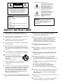
6 Carts and Stands – The unit should be used only with a
cart or stand that is recommended by the manufacturer.
6A A unit and cart combination should be
moved with care. Quick stops, excessive
force, and uneven surfaces may cause
the unit and
cart combination to overturn.
7 Wall or Ceiling Mounting – The unit should be mounted to
a wall or ceiling only as recommended by the
manufacturer.
8 Ventilation – The unit should be situated so that its location
or position does not interfere with its proper ventilation. For
example, the unit should not be situated on a bed, sofa,
rug, or similar surface, that may block the ventilation
openings; or placed in a built-in installation, such as a
bookcase or cabinet that may impede the flow of air
through the ventilation openings.
9 Heat – The unit should be situated away from heat sources
such as radiators, stoves, or other appliances that produce
heat.
10 Power Sources – The unit should be connected to a power
supply only of the type described in the operating
instructions or as marked on the unit.
11 Power-Cord Protection – Power-supply cords should be
routed so that they are not likely to be walked on or
pinched by items placed upon or against them, paying
particular attention to cords at plugs, convenience
receptacles, and the point where they exit from the unit.
12 Cleaning – The unit should be cleaned only as
recommended by the manufacturer.
13 Nonuse Periods – The power cord of the unit should be
unplugged from the outlet when left unused for a long
period of time.
14 Object and Liquid Entry – Care should be taken so that
objects do not fall into and liquids are not spilled into the
inside of the unit.
15 Damage Requiring Service – The unit should be
serviced by qualified service personnel when:
A. The power-supply cord or the plug has been damaged;
or
B. Objects have fallen, or liquid has been spilled into the
unit; or
C. The unit has been exposed to rain; or
D. The unit does not appear to operate normally or
exhibits a marked change in performance; or
E. The unit has been dropped, or the cabinet damaged.
16 Servicing – The user should not attempt to service the unit
beyond those means described in the operating instruc-
tions. All other servicing should be referred to qualified
service personnel.
17 Power Lines – An outdoor antenna should be located away
from power lines.
18 Grounding or Polarization – Precautions should be taken
so that the grounding or polarization is not defeated.
WARNING
TO REDUCE THE RISK OF FIRE OR
ELECTRIC SHOCK, DO NOT EXPOSE
THIS APPLIANCE TO RAIN OR
MOISTURE.
IMPORTANT
Please record the serial number of this system
in the space below.
Model:
Serial No.:
The serial number is located on the rear of the
main unit.
Retain this Owner’s Manual in a safe place for
future reference.

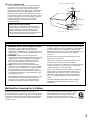
19 For US customers only:
Outdoor Antenna Grounding – If an outside antenna is
connected to this unit, be sure the antenna system is
grounded so as to provide some protection against
voltage surges and built-up static charges. Article 810 of
the National Electrical Code, ANSI/NFPA 70, provides
information with regard to proper grounding of the mast
and supporting structure, grounding of the lead-in wire to
an antenna discharge unit, size of grounding conductors,
location of antenna discharge unit, connection to
grounding electrodes, and requirements for the
grounding electrode.
Note to CATV system installer:
This reminder is provided to call the CATV system
installer’s attention to Article 820-40 of the NEC that
provides guidelines for proper grounding and, in
particular, specifies that the cable ground shall be
connected to the grounding system of the building, as
close to the point of cable entry as practical.
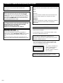
EXAMPLE OF ANTENNA GROUNDING
MAST
GROUND
CLAMP
ANTENNA
LEAD IN
WIRE
ANTENNA
DISCHARGE UNIT
(NEC SECTION 810–20)
GROUNDING CONDUCTORS
(NEC SECTION 810–21)
GROUND CLAMPS
POWER SERVICE GROUNDING
ELECTRODE SYSTEM
(NEC ART 250. PART H)
ELECTRIC
SERVICE
EQUIPMENT
NEC
– NATIONAL ELECTRICAL CODE
We Want You Listening For A Lifetime
YAMAHA and the Electronic Industries Association’s
Consumer Electronics Group want you to get the most out of
your equipment by playing it at a safe level. One that lets the
sound come through loud and clear without annoying blaring
or distortion – and, most importantly, without affecting your
sensitive hearing.
Since hearing damage from loud sounds is often
undetectable until it is too late, YAMAHA and the
Electronic Industries Association’s Consumer
Electronics Group recommend you to avoid
prolonged exposure from excessive volume levels.
FCC INFORMATION (for US customers only)
1. IMPORTANT NOTICE : DO NOT MODIFY THIS UNIT!
This product, when installed as indicated in the
instructions contained in this manual, meets FCC
requirements. Modifications not expressly approved by
Yamaha may void your authority, granted by the FCC, to
use the product.
2. IMPORTANT :
When connecting this product to
accessories and/or another product use only high quality
shielded cables. Cable/s supplied with this product
MUST be used. Follow all installation instructions.
Failure to follow instructions could void your FCC
authorization to use this product in the USA.
3. NOTE : This product has been tested and found to
comply with the requirements listed in FCC Regulations,
Part 15 for Class “B” digital devices. Compliance with
these requirements provides a reasonable level of
assurance that your use of this product in a residential
environment will not result in harmful interference with
other electronic devices.
This equipment generates/uses radio frequencies and, if
not installed and used according to the instructions
found in the users manual, may cause interference
harmful to the operation of other electronic devices.
Compliance with FCC regulations does not guarantee that
interference will not occur in all installations. If this product
is found to be the source of interference, which can be
determined by turning the unit “OFF” and “ON”, please try to
eliminate the problem by using one of the following
measures:
Relocate either this product or the device that is being
affected by the interference.
Utilize power outlets that are on different branch (circuit
breaker or fuse) circuits or install AC line filter/s.
In the case of radio or TV interference, relocate/reorient the
antenna. If the antenna lead-in is 300 ohm ribbon lead,
change the lead-in to coaxial type cable.
If these corrective measures do not produce satisfactory
results, please contact the local retailer authorized to
distribute this type of product. If you can not locate the
appropriate retailer, please contact Yamaha Electronics
Corp., U.S.A. 6660 Orangethorpe Ave, Buena Park, CA
90620.
The above statements apply ONLY to those products
distributed by Yamaha Corporation of America or its
subsidiaries.
1
11

2
22
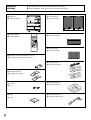
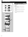
Unpacking ● After unpacking, check that the following parts are contained.
Déballage ● Après le déballage, vérifier que les pièces suivantes sont incluses.
● Main unit
● Appareil principal
● Remote control
● Télécommande
● Batteries (size AA, UM/SUM-3, R6, HP-7)
● Piles (format AA, UM/SUM-3, R6, HP-7)
● Mounting brackets
● Supports de montage
● Screws
● Vis
● Pads
● Patins
● Front speakers
● Enceintes avant
● Center speaker
● Enceinte centrale
● Rear speakers
● Enceintes arrière
● Speaker cords
● Câbles d’enceintes
● AM loop antenna
● Antenne-cadre AM
● Indoor FM antenna
● Antenne intérieure FM
PROGRAM
BASS
BOOST
MUSIC
CENTER/
REAR/DELAY
TEST
LEVEL
VOLUME
POWER
SLEEP
/I
REC/PAUSE
DIRECTION
TAPE
1
1
2
2
3
3
4
4
5
5
6
6
7
7
8
8
9 0
TIME PROG R. TIME
C
EDIT
D
PRESET
+I0
E
MODE REPEAT
RANDOM
TUNER
DISC SKIP
AB
TUNER
CD
INPUT
DISC
1
DISC
2
DISC
3
3
–
DISC CD CHANGER
STANDBY TIMER
DOWN UP
VOLUME
PUSH OPEN
MINI COMPONENT SYSTEM GX–700
STANDBY/ON
AUTO REVERSE CASSETTE DECK
DOLBY B NR
DIRECTION
PROGRAM B.BOOST
MUSIC
INPUTINPUT
PRESET
/
TUNING
/
BAND A
/
B
/
C
/
D
/
E
DISC CHANGE OPEN
/
CLOSE

3
33
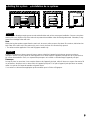
1 cm 1 cm
20 cm20 cm
20 cm
20 cm
20 cm
20 cm 20 cm
20 cm
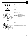
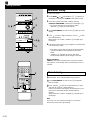
● Setting this system ● Installation de ce système
English
Set this system allowing enough spaces around and behind the main unit to assure good ventilation. Be sure not to place
another unit or any object on top of the main unit to prevent the ventilation holes from being obstructed. Otherwise, it may
cause fire or damage to the main unit.
Note
When placing the speakers apart from the main unit, be sure to allow a space of at least 20 cm above, behind and on
both sides of the main unit. If the main unit is put in a rack, the front of it must be fully opened.
* The values must be applied to China and Singapore models only.
Français
Installer ce système en laissant assez d’espace autour et derrière l’appareil principal pour assurer une bonne
ventilation. Veiller à ne pas empiler un autre appareil ou un autre objet sur l’appareil principal afin de ne pas boucher
les orifices de ventilation. Sinon, on risquerait de provoquer un incendie ou d’endommager l’appareil principal.
Remarque
Lorsqu’on place les enceintes à une certaine distance de l’appareil principal, veiller à laisser un espace d’au moins 20
cm au-dessus, derrière et sur les deux côtés de l’appareil principal. Si l’on place l’appareil principal dans un meuble,
veiller à ce que le côté avant du meuble soit grand ouvert.
*
Les valeurs ne doivent être appliquées qu’aux modèles pour la Chine et Singapour.

4
44
DISC
1
DISC
2
DISC
3
3
–
DISC CD CHANGER
STANDBY TIMER
DOWN UP
VOLUME
STANDBY/ON
AUTO REVERSE CASSETTE DECK
DOLBY B NR
DIRECTION
PROGRAM
B.BOOST
MUSIC
INPUTINPUT
PHONES
MIN
PRESET
/
TUNING
/
BAND A
/
B
/
C
/
D
/
E
DISC CHANGE OPEN
/
CLOSE
TREBLEBASS
AUTO/MANUAL
TIMER
MEMORY
TIME ADJ
REC/PAUSEDOLBY NR
HOUR
RANDOM
REPEAT TIME
DISPLAYMODE
]
\ZX[YW
`
K
J
I
H
G,
U
T
F, S
E
D
C
B, R
A, Q
0, P
LONM
2
3
4
5
6
7
8
9
V
1
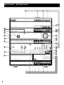
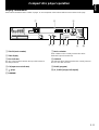
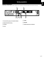
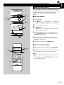
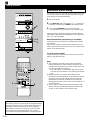
● Front panel ● Panneau avant

5
55
1 Display panel
Panneau d’affichage
2 Remote control sensor
Capteur de télécommande
3 TIMER
4 STANDBY [p. 12]
5 B. BOOST [p. 30]
6 PROGRAM [p. 10, 33]
7 PHONES [p. 31]
8 BASS/TREBLE [p. 30]
9 Front cover
Couvercle avant
0 / [p. 18, 19]
A A/B/C/D/E [p. 19]
B PRESET/TUNING/BAND
[p. 18]
C VOLUME [p. 30]
D MUSIC [p. 31]
E INPUT ( / ) [p. 12, 18, 22, 29]
F HOUR [p. 9, 35]
G MIN [p. 9, 35]
H DISPLAY [p. 9, 35]
I MEMORY [p. 19, 20]
TIME ADJ [p. 9]
J STANDBY/ON [p. 10]
K AUTO/MANUAL [p. 18]
TIMER [p. 35]
L Disc tray
Plateau de disque
[p. 12]
M DISC (1, 2, 3) [p. 13]
N DISC CHANGE [p. 13]
O OPEN/CLOSE [p. 12]
P ( )/ ( ) [p. 13]
Q / [p. 12]
R [p. 12]
S RANDOM [p. 15]
T TIME [p. 16]
U REPEAT [p. 15]
V Tray
Plateau
[p. 22]
W MODE [p. 22]
X [p. 22]
Y DIRECTION [p. 22]
Z ( )/ ( ) [p. 23]
[ [p. 22]
\ [p. 22]
] REC/PAUSE [p. 24]
` DOLBY NR [p. 21, 24]
Amplifier/tuner Amplificateur/tuner
CD player Lecteur de disque compact
Tape deck Platine cassette
TUNER → TAPE → CD
AUX/MD
← VCR ← VIDEO
↑
↓

6
66
1
1
2
2
3
3
4
4
5
5
6
6
7
7
8
8
9 0
TIME PROG R. TIME
C
EDIT
D
PRESET
+I0
E
MODE REPEAT
RANDOM
TUNER
DISC SKIP
REC/PAUSE
DIRECTION
CENTER
/
REAR
/
DELAY
TEST
PROGRAM
BASS
BOOST
MUSIC
POWER
SLEEP
INPUT
VOLUME
AB
TAPE
TUNER
CD
LEVEL
/I
1
1
2
2
3
3
4
4
5
5
6
6
7
7
8
8
9 0
TIME PROG R. TIME
C
EDIT
D
PRESET
+I0
E
MODE REPEAT
RANDOM
TUNER
DISC SKIP
AB
TUNER
CD
REC
/
PAUSE
DIRECTION
CENTER
/
REAR
/
DELAY
TEST
PROGRAM
BASS
BOOST
MUSIC
POWER
SLEEP
INPUT
VOLUME
TAPE
LEVEL
/I
2
3
4
5
6
7
8
E
D
C
A
0
9
B
F
G
I
H
J
KLMNO
P
Q
V
UTS
R
1
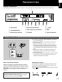
● Remote control ● Telecommande

7
77
1 Transmission window
Fenêtre de transmission
[p. 4]
2 Numeric buttons
Touches numériques
[p. 19]
3 A, B, C, D, E [p. 19]
4 TEST [p. 10]
5 CENTER/REAR/DELAY
[p. 33]
F Numeric buttons
Touches numériques
[p. 13]
G TIME [p. 16]
H PROG [p. 14]
6 LEVEL (+/–)
[p. 10, 33]
7 POWER
[p. 10]
8 SLEEP [p. 36]
9 PRESET ( / )
[p. 19]
0 TUNER [p. 18]
A PROGRAM
[p. 10, 33]
I MODE [p. 12]
J DISC SKIP [p. 13]
K REPEAT [p. 15]
L ( )/ ( ) [p. 13]
M RANDOM [p. 15]
N [p. 12]
O [p. 12]
P EDIT [p. 26]
Q R. TIME [p. 26]
R REC/PAUSE [p. 24]
S / [p. 23]
T [p. 22]
U [p. 22]
B MUSIC [p. 31]
C BASS BOOST
[p. 30]
D VOLUME (+/–)
[p. 30]
E INPUT ( / )
[p. 12, 18, 22, 29]
TUNER → TAPE
↑↓
AUX/MD CD
↑↓
VCR ← VIDEO
Amplifier/tuner Amplificateur/tuner
CD player Lecteur de disque compact
Tape deck Platine cassette
V DIRECTION [p. 22]

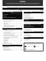
Contents
English
Thank you for purchasing this YAMAHA product. We hope it will give you many years of trouble-free enjoyment.
For the best performance, read this manual carefully. It will guide you in operating your YAMAHA product.
Page
SAFETY INSTRUCTIONS
.............................Inside of the Front Cover
Precautions.................................................
1
Features ......................................................
3
Preparations and connections..................
4
Installing batteries in the remote control .................. 4
Remote control operation range ..............................4
Setting up the speakers ...........................................5
Connections .............................................................7
Setting the clock.......................................................9
Adjusting brightness of the display ..........................9
Speaker balance adjustment .................................10
Compact disc player operation................
11
Basic play...............................................................12
To change the disc play mode ...............................12
To select another disc ............................................ 13
To select the desired track directly ......................... 13
To play the desired track (Skip)..............................13
To advance or reverse play rapidly (Search) .........13
To exchange a disc (or discs) while playing
(PLAYXCHANGE) ..................................................13
Program play..........................................................14
Random play ..........................................................15
Repeat play ............................................................15
Switching the time display......................................16
Tuning operation ......................................
17
Automatic tuning ....................................................18
Manual tuning ........................................................18
Manual preset tuning .............................................19
Automatic preset tuning .........................................20
Page
Playing back a tape..................................
21
General information ............................................... 21
Basic operation ...................................................... 22
Winding the tape ....................................................23
Searching for the beginning
of the desired selection ..........................................23
Recording .................................................
24
Basic recording ...................................................... 24
Recording from CDs utilizing the EDIT function..... 26
Operating the external units connected
with this system .......................................
29
Various sound control .............................
30
General sound control............................................ 30
Graphic equalizer...................................................31
Sound field processor ............................................32
Using the built-in timer ............................
35
Timer play ..............................................................35
Timer recording......................................................36
Sleep timer operation.............................................36
Appendix...................................................
37
Troubleshooting ..................................................... 37
Specifications.........................................................39
For basic source play, the following illustrations on top of
pages will help you to look for the section you need.
..... CD play ..... Tuning
..... Tape playback/recording

E-1
English
■ To assure the finest performance, please read this manual
carefully. Keep it in a safe place for future reference.
■ Choose the installation location of this system carefully.
Avoid placing it in direct sunlight or close to a source of
heat. Also avoid locations subject to vibration and
excessive dust, heat, cold or moisture. Keep it away from
sources of hum such as transformers and electric motors.
■ Do not operate this system upside-down. It may overheat,
possibly causing damage.
■ Never open the cabinet. If something drops into the set,
contact your dealer.
■ The openings on the main unit cover assure proper
ventilation of the main unit. If these openings are
obstructed, the temperature inside the unit will rise rapidly.
Therefore, avoid placing objects against these openings,
and install the main unit in a well-ventilated area to
prevent fire and damage.
■ Always set the VOLUME control to minimum before
starting an audio source play: increase the volume
gradually to an appropriate level after play has started.
■ When not planning to use this system for long periods of
time (ie., vacation, etc.), disconnect the AC power plug
from the wall outlet.
■ Grounding or polarization – Precautions should be taken
so that the grounding or polarization of this system is not
defeated.
■ Do not use force on switches, controls or connection
wires. When moving the main unit, first disconnect the
power plug and the wires connected to other equipment.
Never pull the wire itself.
■ If an external appliance (TV, radio, etc.) interferes with this
system operation, move the main unit away from such an
appliance.
■ Do not attempt to clean this system with chemical
solvents; this might damage the finish. Use a clean, dry
cloth.
■ Be sure to read the “Troubleshooting” section regarding
common operating errors before concluding that this
system is faulty.
■ To prevent lightning damage, disconnect the AC power
plug and the antenna cable when there is an electrical
storm.
■ Do not plug the AC power plug to the wall socket before
you finish all connections.
■ Never allow metallic items (e.g. screwdrivers, tools, etc.) to
come near the tape deck’s record/playback head
assembly. Doing so may not only scratch or damage the
head’s mirror-smooth finish, it may change the magnetic
characteristics of the heads, causing a deterioration in
reproduction performance quality.
■ Although the tape deck’s record/playback heads are high
quality heads with outstanding reproduction
characteristics, they can become dirty through the use of
old tapes or from dust accumulation over time. This can
have a serious effect on reproduction quality. Clean the
heads regularly with one of the commonly available head
cleaners or with cleaning solutions.
■ The voltage to be used must be the same as that specified
on this system. Using this system with a higher voltage
than specified is dangerous and may result in a fire or
other types of accidents causing damage. YAMAHA will
not be held responsible for any damage resulting from use
of this system with a voltage other than specified.
■ The sound level at a given volume setting depends on
speaker location and other factors. Care should be taken
to avoid exposure to sudden high levels of sound, which
may occur when turning on this system with the volume
control setting at high, and to continuous high levels of
sound.
■ Sudden temperature changes and storage or operation in
an extremely humid environment may cause condensation
inside the cabinet. Condensation can cause this system to
malfunction.
To eliminate condensation:
•
CD pickup
Leave the power on with no disc loaded until normal
play becomes possible (about 1 hour).
•
Tape head
Leave the power on with no tape loaded until normal
playback becomes possible (about 1 hour).
Note
If condensation forms on the tape head, dirt or dust
may accumulate during use.
•
Remote control
Wipe off condensation on the transmission window
with a soft cloth before operating this system.
■ To prevent a malfunction of this system:
•
Do not use any non standard shaped disc (heart etc.)
available on the market, because it may damage this
system.
•
Do not use a disc with tape, seals, or paste on it,
because damage to this system may result.
Precautions: Read this before operating your system
This system is not disconnected from the AC power
source as long as it is connected to the wall outlet, even if
this system itself is turned off. This state is called the
standby mode.
In this state, this system is designed to consume a certain
level of power.
Note
Please check the copyright laws in your country to record
from records, compact discs, radio, etc. Recording of
copyright material may infringe copyright laws.

E-2
Precautions: Read this before operating your system
IMPORTANT
Please record the serial number of this system in the space
below.
Model:
Serial No.:
The serial number is located on the rear of the main unit.
Retain this Owner’s Manual in a safe place for future
reference.
WARNING
TO REDUCE THE RISK OF FIRE OR ELECTRIC SHOCK,
DO NOT EXPOSE THIS APPLIANCE TO RAIN OR
MOISTURE.
WARNING
To reduce the risk of fire or electric shock, do not expose this
system to rain or moisture.
To avoid electrical shock, do not open the cabinet. Refer
servicing to qualified personnel only.
CAUTION
Use of controls or adjustments or performance of
procedures other than those specified herein may result in
hazardous radiation exposure.
As the laser beam used in this system is harmful to the
eyes, do not attempt to disassemble the cabinet. Refer
servicing to qualified personnel only.
This system is classified as a
CLASS 1 LASER product.
The CLASS 1 LASER
PRODUCT label is located on
the rear exterior.
CLASS 1 LASER PRODUCT
Laser component in this product is capable of emitting
radiation exceeding the limit for Class 1.
CAUTION FOR CARRYING THE MAIN UNIT
Be sure not to carry or tip the main unit with discs
remaining in it.
CAUTION FOR MOVING THE MAIN UNIT
Before moving the main unit, first remove all discs from
the disc tray and close the tray by pressing the OPEN/
CLOSE button. After you confirm that “NO DISC” lights up
on the display, turn this system into the standby mode by
pressing the STANDBY/ON switch, and then disconnect
the power plug from the AC outlet.
Voltage Selector (China and General models only)
The voltage selector on the rear panel of the main unit
must be set for your local main voltage BEFORE
plugging into the AC main supply.
Voltages are 110/120/220/240 V AC, 50/60 Hz.
FREQUENCY STEP switch
(China and General models only)
Because the interstation frequency spacing differs in
different areas, set the FREQUENCY STEP switch (located
at the rear) according to the frequency spacing in your
area.
Be sure to change the setting of this switch with the AC
supply lead of this system disconnected from the AC outlet.

E-3
English
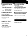
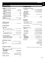
Features
General
●
5-Speaker Multichannel Audio System
(Two front, One Center and Two Rear
Speakers)
●
High Power Output
Front L, R: 80W + 80W (6Ω) RMS, 0.9%
THD, 1 kHz
Center: 80W (6Ω) RMS Output
Power,
0.9% THD, 1 kHz
Rear: 25W (6Ω) RMS Output
Power,
0.9% THD, 1 kHz
● 4 External Audio/Video Component
Connecting Capability
● Multiuse Timer/Sleep Timer
● SUBWOOFER Output for Low Frequency
Expansion
● Remote Control Capability
● BASS BOOST
● 5-Band Spectrum Analyzer
● DOLBY PRO LOGIC and DOLBY 3
STEREO Decoding
● Sound Field Processing
(HALL and YMERSION)
● Test Tone Generator for Easier Speaker
Balance Adjustment
● 3 Preset Graphic Equalizer Modes
(ROCK, POPS and JAZZ)
Compact Disc Player
●
3-Disc Carousel Type CD Changer
● PLAYXCHANGE
Disc changing while playing
● 20-Track Random Access Programming
● Repeat Play for Single Track/Entire Disc/
All Discs
● Random Sequence Play
Tape Deck
● Automatic Synchronized Recording with
CD
● EDIT Function Useful for Recording
CD(s)
●
Automatic Reverse
●
Dolby B Type Noise Reduction System
Tuner
●
40 Station Preset Tuning
●
Automatic Preset Tuning

E-4
SET MD
REC/PAUSE
TAPE
DISC
1
DISC
2
DISC
3
3
–
DISC VCD CHANGER
DOWN UP
VOLUME
PUSH OPEN
MINI COMPONENT SYSTEM GX–700
MINIDISC RECORDER
MD
PRESET
/
TUNING
/
BAND A
/
B
/
C
/
D
/
E
DISC CHANGE OPEN
/
CLOSE
MODE
–
PTY SEEK
–
START
30°
30°
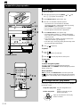
Preparations and connections
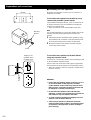
1. Turn the remote control over and remove the battery
compartment cover by pulling it up while pressing the edge
of the cover in the direction of the mark.
2. Insert the batteries (AA, R6, UM-3 type) according to the
polarity markings on the inside of the battery compartment.
3. Attach the battery compartment cover.
Notes
● Remove the batteries if the remote control is not used for an
extended period of time.
● If batteries leak, dispose of them immediately. Avoid
touching the leaked material and contact with clothing, etc.
Clean the battery compartment thoroughly before installing
new batteries.
● Be sure to use the same type of batteries together.
● Do not use a new battery and an old battery together.
Installing batteries in the remote control
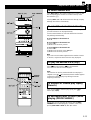
Notes
● The area between the remote control and the main unit must
be clear of large obstacles.
● Do not expose the remote control sensor to strong lighting,
in particular, an inverter type fluorescent lamp. Otherwise,
the remote control may not work properly. If necessary,
position the main unit away from direct lighting.
Battery replacement
If you find that the remote control must be used closer to the
main unit, the batteries are weak. Replace both batteries with
new ones.
Remote control operation range
2
1
3
0,2 m – 6 m
(8” – 20’)

E-5
English
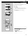
Setting up the speakers
m 4 channel 5 speaker configuration
This system employs a 5 speaker configuration: 2 front
speakers, 2 rear paralleled speakers and a center speaker.
The front speakers are used for outputting main source sound.
The rear speakers are for effect and surround sounds when
the sound field program
PRO LOGIC or HALL is selected.
The center speaker is for center sounds (dialog etc.) when the
sound field program PRO LOGIC or 3 STEREO is
selected.
m Placing the speakers
Front speakers: On both sides of the TV and almost the
same height as the TV.
Center speaker: Precisely between the front speakers.
Rear speakers: Behind your listening position, facing
slightly inward. Nearly 1.8 m (approx. six
feet) up from the floor.
Subwoofer: The position of the subwoofer is not so
(separate purchase)
critical because low bass tones are not
highly directional.
m Mounting the center speaker
Place the center speaker on the TV, on the floor under the TV
or in the TV rack so that it is stabilized.
When placing the speaker on top of the TV, to prevent the
speaker from falling down, put the provided pads at four points
on bottom of the speaker.
Preparations and connections
Front L Center Front R
DialogueDialogo
Rear L Rear R
Front L
TV set
Front R
Center
Rear L
Rear R
Subwoofer

E-6
Preparations and connections
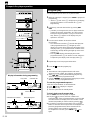
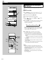
m Mounting the rear speakers
Mount the rear speakers on a shelf, rack or on the floor, or
hang them on the wall.
To mount the rear speakers on the wall by using
commercially available speaker stands
The provided mounting bracket has 1 pair of screw holes (at
an interval of 60 mm). They are available for mounting the
speaker on a speaker stand.
* Those screw holes can be used with M4 screws only.
Note
It is recommended that you connect the speaker cords to the
speaker’s terminals before attaching the bracket to the
speaker.
1 Attach the bracket to the bottom of the speaker by using
the provided screw so that the convex part of the bracket
fits in the grooved part of the speaker as figured left.
2 Mount the speaker on the speaker stand by using the
screw holes on the bracket.
To mount the rear speakers on the wall without
using any bracket or stand
If desired, you can hang the speaker on the protruding screws
on the wall without using the bracket.
Fasten screws into a firm wall or wall support as figured left,
and hang the holes of the speaker on the protruding screws.
* Make sure that the screws are caught by a narrow part of
the holes securely.
WARNING:
● Each of the rear speakers weighs 0.8 kg (1 lbs. 12 oz.).
Do not mount them on thin plywood or soft wall
surface material, as the screws may come out of the
flimsy surface, causing the speakers to fall down and
be damaged, or result in personal injury.
● Do not fasten the speakers to the wall with nails,
adhesives, or other unsound hardware. Long-term use
and vibrations may cause them to fall down.
● To avoid accidents resulting from tripping over loose
speaker cords, fix them to the wall.
● Select a proper position on the wall to mount the
speaker and the stand so that no one will hit his head
or forehead on the projections of them, resulting in
personal injury.
60 mm
Mounting
bracket
Screw
Tapping screw
(Available at the
hardware store)
Min.
12 mm
65 mm
Wall or wall
support

E-7
English
Preparations and connections
Never plug the AC supply lead of this system into the AC outlet until all connections are completed.
Connections
Caution
Do not let the bare speaker wires touch each other as this could damage the amplifier and/or speakers.
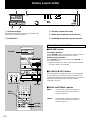
When connecting a subwoofer (separate purchase)
You may wish to add a subwoofer to reinforce the bass frequencies.
When connecting a subwoofer to this system, connect the SUBWOOFER OUT terminal of this system to the INPUT terminal of the
subwoofer.
* Ordinary subwoofers, including the Yamaha Active Servo Processing Subwoofer System, are designed so that the amplifier and
subwoofer are in the same unit.
* The SUBWOOFER OUT terminal outputs low frequencies from the left front, center and right front channels.
(The cut-off frequency of this terminal is 200 Hz.)
m Connecting speakers
Connect the speakers to the corresponding speaker terminals on the rear of the main unit respectively by using the speaker cords.
Make sure that the polarity of the speaker cords is correct, that is the + and – markings are observed. If these cords are reversed,
the sound will be unnatural and lack bass.
On the main unit
Red: positive (+)
Black: negative (–)
1 Press up the tab.
2 Insert the bare wire.
[Remove approx. 5mm (1/4”)
insulation from the speaker
wires.]
3 Press down the tab and
secure the wire.
1
2
3
On the speakers
Red: positive (+)
Black: negative (–) 1 Press the tab
2 Insert the bare wire.
[Remove approx. 5mm
(1/4”) insulation from
the speaker wires.]
3 Release the tab and
secure the wire.
MAINS
RL
OUT
IN
AUX/MD
VIDEO SIGNAL
MONITOR
OUT
OUT
VCR
IN
VIDEO
OUT
SUBWOOFER
SPEAKERS
SEE OWNER’S MANUAL
FOR CONNECTION.
SPEAKERS
CENTER: 6
Ω
MIN./SPEAKER
REAR: I 2
Ω
MIN./SPEAKER
CENTERREAR REAR
R L
6
Ω
MIN./SPEAKER
FRONT
R L
R
L
L R
INPUT
Subwoofer system
(Separate purchase)
Rear speaker
1
2
3
Front speakers
Rear speaker
Center speaker
To AC outlet
(U.S.A model)

E-8
Preparations and connections
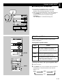
m Connecting external components
This system can be connected with external audio and video
components. Make connections between this system and the
components using RCA pin plug connector cables correctly,
that is to say L (left) to L and R (right) to R. Also, refer to the
owner’s manual for the component to be connected to this
system.
* A digital-to-digital recording is possible from a CD played on
the built-in CD player to an MD (or tape) on an external MD
recorder (or DAT) by connecting the DIGITAL OUT
(OPTICAL) terminal on the rear of the main unit to the MD
recorder (or DAT).
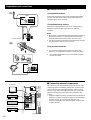
m Antenna connection
(1) Supplied FM antenna
Connect the FM antenna wire to the corresponding terminal
and direct the FM antenna wire to the direction where the
strongest signal can be received.
(2) Supplied AM loop antenna
Connect the AM loop antenna wires to the corresponding
terminals. Position the AM loop antenna for optimum
reception.
Notes
● When static is still heard even after adjusting the position of
the AM loop antenna, try reversing the wire connections
(from the right terminal to the left one, and vice versa).
● The AM loop antenna should be placed apart from the main
unit. The antenna may be hung on a wall.
Using an external antenna
● Use an external FM antenna instead of an indoor FM
antenna if you need better reception. Consult your dealer.
● Use an external AM antenna if you need better reception.
Consult your dealer.
(1)
(2)
ANTENNA
75Ω UNBAL.
FM GND AM
ANTENNA
75Ω UNBAL.
FM GND AM
DIGITAL OUT
OPTICAL
ANTENNA
75Ω UNBAL.
FM GND AM
DIGITAL OUT
OPTICAL
RL
OUT
IN
AUX/MD
VIDEO SIGNAL
MONITOR
OUT
OUT
VCR
IN
VIDEO
OUT
SUBWOOFER
SPEAKERS
SEE OWNER’S
M
FOR CONNECTI
O
CENTER: 6
Ω
MIN./
S
REAR: I 2
Ω
MIN./
S
CENTERREAR
R
FRONT
R
L
TV monitor
VCR
LD/DVD player, etc.
MD recorder, etc.
(U.S.A. model)
(U.S.A. model)

English
E-9
DISC
1
DISC
2
DISC
3
3
–
DISC CD CHANGER
STANDBY TIMER
DOWN UP
VOLUME
STANDBY/ON
AUTO REVERSE CASSETTE DECK
DOLBY B NR
DIRECTION
PROGRAM
B.BOOST
MUSIC
INPUTINPUT
PHONES
MIN
PRESET
/
TUNING
/
BAND A
/
B
/
C
/
D
/
E
DISC CHANGE OPEN
/
CLOSE
TREBLEBASS
AUTO/MANUAL
TIMER
MEMORY
TIME ADJ
REC/PAUSEDOLBY NR
HOUR
RANDOM
REPEAT TIME
DISPLAYMODE
1
2
3
RANDOM
REPEAT
HOUR
MIN
RANDOM
REPEAT
HOUR
MIN
DISPLAY
MEMORY
TIME ADJ
MEMORY
TIME ADJ
DISC
1
DISC
2
DISC
3
DOWN UP
VOLUME
STANDBY/ON
PROGRAM
B.BOOST
MUSIC
INPUTINPUT
MIN
PRESET
/
TUNING
/
BAND A
/
B
/
C
/
D
/
E
DISC CHANGE OPEN
/
CLOSE
AUTO/MANUAL
TIMER
MEMORY
TIME ADJ
REC/PAUSEDOLBY NR
HOUR
RANDOM
REPEAT TIME
DISPLAYMODE
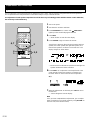
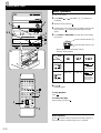
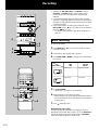
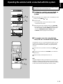
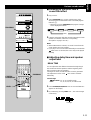
1 While the power is on, press DISPLAY to display the time.
2 While holding TIME ADJ pressed, press HOUR and set the
hour.
* Press HOUR once to advance the time by 1hour. Press
and hold to advance continuously.
3 While holding TIME ADJ pressed, press MIN and set the
minute.
* Press MIN once to advance the time by 1
minute. Press and hold to advance continuously.
* The hour setting will not advance even if minute is
advanced from “59” to “00”.
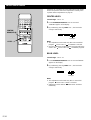
Australia model use a 24-hour display. U.S.A. and Canada
models use a 12-hour display. For China and General
models, either the 24-hour display or the 12-hour display
[shown by “AM (PM) 12:00”] is selected depending on the
setting of the FREQUENCY STEP switch on the rear
panel, so you cannot select the desired type freely.
Note
In the event of a power failure or when the AC supply lead is
disconnected, the time display will go out, however, the clock
will function for about 5 minutes without any power supply.
Otherwise, the time display will flash on and off to indicate that
the time must be reset.
If desired, you can adjust the brightness of the display.
Press and hold DISPLAY for more than 2 seconds so that
“DIMMER ±0” appears on the display.
While holding DISPLAY pressed, turn VOLUME clockwise to
increase or counterclockwise to decrease brightness.
Control range: ±0 to –6 (Preset value: ±0)
Setting the clock
Adjusting brightness of the display
Changes.
Changes.
Preparations and connections
VOLUME
DISPLAY

E-10
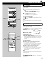
Preparations and connections
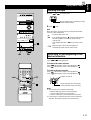
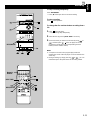
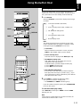
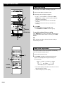
1 Turn on the power.
2 Turn down the volume to minimum.
3 Press PROGRAM once or more until “ PRO LOGIC”
lights up on the sound field program indicator.
4 Press TEST.
* “TEST” flashes on and off on the display.
5 Press VOLUME + (up) to increase the volume.
You will hear a test tone (like pink noise) from the left front
speaker, the center speaker, the right front speaker, and
then the rear speakers, for about 2.5 seconds each. The
display changes as shown below.
* The test tone from the left rear speaker and the right rear
speaker will be heard at the same time.
6 Press LEVEL +/– to adjust the sound output levels of the
center speaker and the rear speakers so that the level
becomes almost as same as that of the front speakers.
ex.)
7 When the adjustments are finished, press TEST to cancel
the test tone.
* “TEST” disappears from the display.
Note
Once you have completed these adjustments, you can adjust
whole sound level on your audio system by using VOLUME on
the main unit (or the remote control).
Speaker balance adjustment
You can adjust the sound output level balance between the front, center, and rear speakers using the built-in test tone generator.
This is important for the best performance of the built-in Dolby Pro Logic surround decoder.
The adjustment of each speaker output level should be done at your listening position with the remote control. Otherwise,
the result may not be satisfactory.
PROGRAMMUSIC
TEST
CD
PRO LOGIC
PROGRAM
BASS
BOOST
MUSIC
CENTER/
REAR/DELAY
TEST
LEVEL
VOLUME
POWER
SLEEP
/I
REC/PAUSE
DIRECTION
TAPE
1
1
2
2
3
3
4
4
5
5
6
6
7
7
8
8
9 0
TIME PROG R. TIME
C
EDIT
D
PRESET
+
I0
E
MODE REPEAT
RANDOM
TUNER
DISC SKIP
AB
TUNER
CD
INPUT
3
2, 5
4, 7
6
1
Changes.
La page charge ...
La page charge ...
La page charge ...
La page charge ...
La page charge ...
La page charge ...
La page charge ...
La page charge ...
La page charge ...
La page charge ...
La page charge ...
La page charge ...
La page charge ...
La page charge ...
La page charge ...
La page charge ...
La page charge ...
La page charge ...
La page charge ...
La page charge ...
La page charge ...
La page charge ...
La page charge ...
La page charge ...
La page charge ...
La page charge ...
La page charge ...
La page charge ...
La page charge ...
La page charge ...
-
 1
1
-
 2
2
-
 3
3
-
 4
4
-
 5
5
-
 6
6
-
 7
7
-
 8
8
-
 9
9
-
 10
10
-
 11
11
-
 12
12
-
 13
13
-
 14
14
-
 15
15
-
 16
16
-
 17
17
-
 18
18
-
 19
19
-
 20
20
-
 21
21
-
 22
22
-
 23
23
-
 24
24
-
 25
25
-
 26
26
-
 27
27
-
 28
28
-
 29
29
-
 30
30
-
 31
31
-
 32
32
-
 33
33
-
 34
34
-
 35
35
-
 36
36
-
 37
37
-
 38
38
-
 39
39
-
 40
40
-
 41
41
-
 42
42
-
 43
43
-
 44
44
-
 45
45
-
 46
46
-
 47
47
-
 48
48
-
 49
49
-
 50
50


Yamaha GX-700 Manuel utilisateur
- Catégorie
- Lecteur CD
- Taper
- Manuel utilisateur
- Ce manuel convient également à
dans d''autres langues
- italiano: Yamaha GX-700 Manuale utente
- English: Yamaha GX-700 User manual
- español: Yamaha GX-700 Manual de usuario
- Deutsch: Yamaha GX-700 Benutzerhandbuch
- русский: Yamaha GX-700 Руководство пользователя
- Nederlands: Yamaha GX-700 Handleiding
- português: Yamaha GX-700 Manual do usuário
- dansk: Yamaha GX-700 Brugermanual
- polski: Yamaha GX-700 Instrukcja obsługi
- čeština: Yamaha GX-700 Uživatelský manuál
- svenska: Yamaha GX-700 Användarmanual
- Türkçe: Yamaha GX-700 Kullanım kılavuzu
- suomi: Yamaha GX-700 Ohjekirja
- română: Yamaha GX-700 Manual de utilizare
Documents connexes
-
Yamaha GX-505 Le manuel du propriétaire
-
-
-
-
-
-
-
-
-