Yamaha SY85 Manuel utilisateur
- Catégorie
- Instruments de musique
- Taper
- Manuel utilisateur

YAMAHA
SY85 Music Synthesizer
Owner’s Manual 2
- Feature Reference -

GENERAL EDITING PROCEDURE
PATTERN EDIT MODE
SONG EDIT MODE
DRUM VOICE EDIT MODE
VOICE EDIT MODE
PERFORMANCE EDIT MODE
UTILITY MODE
WAVE EDIT MODE
APPENDIX

2
CONTENTS
GENERAL EDITING PROCEDURE
■ Mode Selection .............................................8
■ Selecting Specific Edit Functions...............8
■ Selecting & Editing Parameters................10
■ Controller Assignment Display..................11
Performance Edit Mode
■ Edit
1: Layer
1: Voice Number .................................14
2: Volume .............................................15
3: Pan ...................................................16
4: Tune .................................................17
5: Note Limit ........................................18
6: Velocity Limit...................................20
7: CS Enable .......................................22
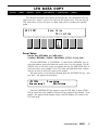
Layer Data Copy.................................23
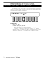
2: Performance Total Level .....................24
3: Performance Name ..............................25
4: Layer Voice Edit
1: Oscillator..........................................26
2: Amplitude EG..................................26
3: Filter .................................................26
4: Pitch EG ..........................................26
5: LFO ..................................................26
6: Controller .........................................26
7: Voice Total Level ...........................26
8: Voice Name.....................................26
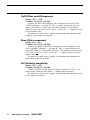
■ Quick Edit
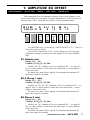
1: Amplitude EG Offset............................27
2: LFO & Filter Offset ..............................29
3: Controller Conditions ...........................31
4: Other Conditions ..................................33
5: Effect Type............................................35
6: Effect Parameter ..................................36
■ Effect Edit
1: Mode, Type ...........................................37
2: Send Select & Level............................38
3: Layer Dry Output Select .....................40
4: Output Level .........................................41
5: Wet : Dry Balance ...............................42
6: Send & Effect 2 Mix Level .................43
7: Effect 1 Parameters.............................44
8: Effect 2 Parameters.............................44
9: Control Parameters ..............................45
10: Control LFO ........................................47
Effect Data Copy.......................................48
Effect Signal Flow Display.......................49
■ Job
1: Layer Controller Sync..........................50
2: Layer Exchange....................................51
3: Performance Edit Recall .....................52
4: Performance Initialize ..........................53
■ Performance Compare...............................54
■ Performance Store .....................................55
Voice Edit Mode
■ Edit
1: Oscillator................................................58
2: Amplitude EG
1: AEG Level & Rate .........................60
2: Level Scaling ..................................62
3: Sensitivity ........................................63
AEG Data Copy...................................64
3: Filter
1: Type, Cutoff Frequency.................65
2: Cutoff Scaling .................................69
3: FEG Level & Rate..........................70
4: Filter Sensitivity ..............................72
Filter Data Copy..................................73
4: Pitch EG
1: Level & Rate...................................74
2: Range, Sensitivity...........................76
Pitch EG Data Copy...........................77
5: LFO
1: LFO ..................................................78

3
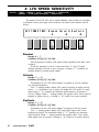
2: LFO Speed Sensitivity...................80
LFO Data Copy ...................................81
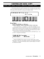
6: Controller
1: Pitch Bend Range ..........................82
2: Modulation Wheel Depth ...............83
3: Foot Controller Depth ....................85
4: After Touch Depth..........................87
5: CS3 Parameter Edit.......................89
6: CS4 Parameter Edit.......................91
Controller Data Copy..........................93
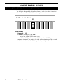
7: Voice Total Level ...........................94
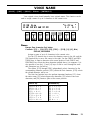
8: Voice Name.....................................95
■ Quick Edit
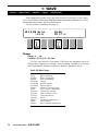
1: Wave......................................................96
2: Amplitude EG........................................98
3: Filter.................................................... 100
4: LFO ..................................................... 102
5: Effect Type......................................... 103
6: Effect Parameter ............................... 104
■ Effect Edit
1: Mode, Type ........................................ 105
2: Send, Mix, Wet : Dry........................ 106
3: Output Level ...................................... 108
4: Effect 1 Parameters.......................... 109
5: Effect 2 Parameters.......................... 109
6: Control Parameters ........................... 110
7: Effect LFO.......................................... 112
Effect Data Copy.................................... 113
Effect Signal Flow Display.................... 114
■ Job
1: Voice Edit Recall............................... 115
2: Voice Initialize ................................... 116
■ Voice Compare ........................................ 117
■ Voice Store............................................... 118
Drum Voice Edit Mode
■ Edit
1: Key Parameters 1 ............................. 120
2: Key Parameters 2 ............................. 122
3: Total Level ......................................... 123
4: Drum Voice Name............................. 124
Drum Key Data Copy ............................ 125
■ Quick Edit
1: Effect Type......................................... 126
2: Effect Send Level.............................. 127
■ Effect Edit
1: Mode, Type ........................................ 128
2: Key Send Select & Level................. 129
3: Key Dry Output Select ..................... 131
4: Output Level ...................................... 132
5: Wet : Dry Balance ............................ 133
6: Send & Effect 2 Mix Level .............. 134
7: Effect 1 Parameter2.......................... 135
8: Effect 2 Parameter2.......................... 135
9: Control Parameters ........................... 136
10: Control LFO ..................................... 138
Effect Data Copy.................................... 139
Effect Signal Flow Display.................... 140
■ Job
1: Key Data Initialize............................. 141
2: Key Data Exchange .......................... 142
3: Drum Voice Edit Recall.................... 143
4: Drum Voice Initialize......................... 144
■ Drum Voice Compare ............................. 145
■ Drum Voice Store.................................... 146

4
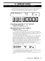
Song Edit Mode
■ Multi Edit
1: Voice Select ....................................... 148
2: Volume................................................ 149
3: Pan...................................................... 150
4: Effect Send Level.............................. 151
5: Note Shift ........................................... 152
6: Tune.................................................... 153
7: Effect Type, Out Balance................. 154
8: Song Name ........................................ 155
9: Song Initialize .................................... 156
■ Track Edit ................................................. 157
■ Effect Edit
1: Mode, Type ........................................ 166
2: Send Select & Level......................... 167
3: Inst Dry Output Select...................... 169
4: Output Level ...................................... 170
5: Wet : Dry Balance ............................ 171
6: Send & Effect 2 Mix Level .............. 172
7: Effect 1 Parameters.......................... 173
8: Effect 2 Parameters.......................... 173
9: Control Parameters ........................... 174
10: Control LFO ..................................... 176
Effect Data Copy.................................... 177
Effect Signal Flow Display.................... 178
■ Job
1: Clear Song ......................................... 179
2: Copy Song ......................................... 180
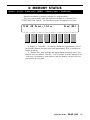
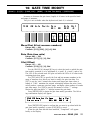
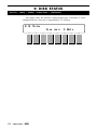
3: Memory Status/Clear Rhythm Track
.................................................... 181,182
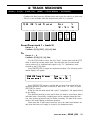
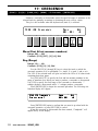
4: Track Mixdown................................... 183
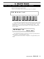
5: Delete Track ...................................... 185
6: Quantize ............................................. 186
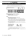
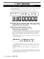
7: Copy Measure ................................... 188
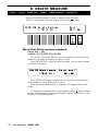
8: Delete Measure ................................. 190
9: Insert Measure................................... 191
10: Erase Measure ................................ 192
11: Remove Event ................................. 193
12: Clock Move ...................................... 195
13: Transpose......................................... 196
14: Note Shift ......................................... 197
15: Velocity Modify ................................ 198
16: Gate Time Modify ........................... 199
17: Crescendo ........................................ 200
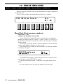
Pattern Edit Mode
■ Job
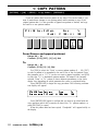
1: Copy Pattern...................................... 202
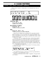
2: Clear Pattern...................................... 203
3: Instrument Change............................ 204
4: Velocity Modify .................................. 205
■ Pattern Name........................................... 207
Utility Mode
■ Synth Setup
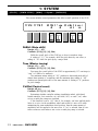
1: System................................................ 210
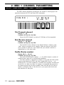
2: MIDI 1 (Channel Parameters) ......... 212
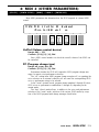
3: MIDI 2 (Other Parameters).............. 213
4: Program Change Table .................... 215
5: Velocity ............................................... 216
■ SEQ Setup
1: Click Condition................................... 217
2: Record Condition............................... 219
3: Accent Velocity.................................. 220
4: Song Chain ........................................ 221
■ Bulk Dump
1: all......................................................... 222
2: synth all.............................................. 222
3: sequencer all ..................................... 222
4: pattern all ........................................... 222
5: 1 performance.................................... 222
6: 1 voice ................................................ 222
7: 1 song................................................. 222

5
■ Card
1: Card All Load/Save........................... 223
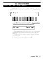
2: Card Format....................................... 224
■ Disk
1: Disk All Load/Save............................ 225
2: Disk All Load/Save Synth ................ 225
3: Disk All Load/Save Seq ................... 225
4: Disk NSEQ Load/Save ..................... 225
5: Disk Other Load/Save ...................... 225
6: MDR .................................................... 228
7: Rename/Delete .................................. 231
8: Backup Disk....................................... 232
9: Disk Status......................................... 234
10: Disk Format ..................................... 235
Wave Edit Mode
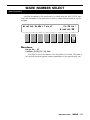
■ Wave Number Select .............................. 239
■ Edit
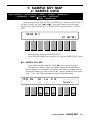
1: Waveform
1: Wave Assign ................................ 240
2: Wave Name ................................. 240
2: Sample
1: Sample Key Map......................... 243
2: Sample Data ................................ 243
■ Wave Initialize.......................................... 247
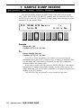
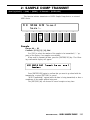
■ Sample Dump
1: Sample Dump Recieve..................... 248
2: Sample Dump Transmit.................... 249
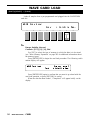
■ Wave Card Load ..................................... 250
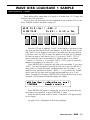
■ Wave Disk Load/Save 1 Sample .......... 251
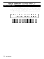
■ Wave Memory Status Display................ 252
APPENDIX
■ EFFECTS.................................................. 254
Effect Signal Flow Diagrams — Voice
Mode........................................................ 256
Effect Signal Flow Diagrams — Drum Voice,
Performance, and Song Modes..................
264
The Effects & Their Parameters.......... 274
■ WAVE MEMORY EXPANSION.............. 285
Memory Installation................................ 286
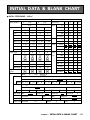
■ INITIAL DATA & BLANK CHART
INITIAL PERFORMANCE “InitPerf” ..... 289
INITIAL NORMAL VOICE “InitVce”...... 290
INITIAL DRUM VOICE “DR PTN”........ 292
INITIAL DRUM VOICE “DR Zones”..... 294
INITIAL DRUM VOICE “DR GMIDI” .... 296
INITIAL DRUM VOICE “DR Efect” ...... 298
INITIAL MULTI “InitSong” ..................... 300
SYSTEM SETUP.................................... 301
INTERNAL PERFORMANCE LIST (1)....
302
INTERNAL PERFORMANCE LIST (2)....
304
INTERNAL VOICE LIST (1).................. 306
INTERNAL VOICE LIST (2).................. 307
INTERNAL VOICE LIST (3).................. 308
INTERNAL VOICE LIST (4).................. 309
INTERNAL WAVE LIST......................... 310
BLANK CHART — PERFORMANCE... 311
BLANK CHART — VOICE.................... 312
BLANK CHART — DRUM VOICE ....... 314
BLANK CHART — MULTI .................... 316
BLANK CHART — SYSTEM SETUP .. 317
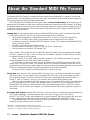
■ About the Standard MIDI File Format .. 318
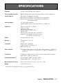
■ SPECIFICATIONS ................................... 319
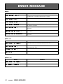
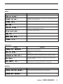
■ ERROR MESSAGES............................... 320
■ TROUBLE SHOOTING............................ 324
■ INDEX ....................................................... 326


GENERAL EDITING
PROCEDURE
■ Mode Selection ........................................... 8
■ Selecting Specific Edit Functions ............... 8
■ Selecting & Editing Parameters ............... 10
■ Controller Assignment Display ................. 11

8
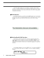
The SY85 makes editing easy by providing a consistent, logical control
interface via which parameters can be located and edited. Once you’ve learned
the general procedure, you can locate and edit any of the SY85’s many param-
eters quickly and easily.
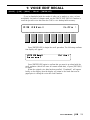
■ Mode Selection
All SY85 edit modes are selected via the MODE matrix keys. To select the
VOICE EDIT mode, for example, press the VOICE mode key so that its indica-
tor lights, than press the second SUB MODE key in the VOICE column
(EDIT).
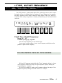
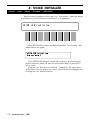
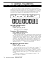
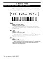
■ Selecting Specific Edit Functions
Once you’ve selected an edit mode, one way to select the various edit
screens and functions it contains is to use the PAGE [ ] and [ ] keys. The
[ ] and [ ] keys step backward and forward through the available screens,
respectively. Hold either of these keys for continuous stepping in the specified
direction.
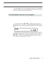
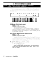
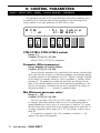
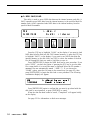
An alternative method is to use the [MENU] key. If you press the [MENU]
key ion the VOICE EDIT mode, for example, you’ll see a display something
like this:
GENERAL EDITING PROCEDURE
The illustrations here are not available.

9
From this display you can use either the data entry dial or the [-1] and [+1]
keys to directly select any of the 8 available functions, then press the [ENTER/
YES] key to actually select the specified function.
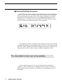
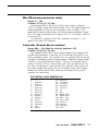
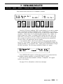
In some cases the PAGE [ ] and [ ] or [MENU] keys will take you to
another entry screen. If you select “3: Filter” after pressing the [MENU] key in
the VOICE EDIT mode, and then press [ENTER/YES], you’ll see the following
display:
“Hit [ENTER]” will be flashing. In this case press [ENTER/YES] again to
access the filter functions. Once in the filter “sub-mode” you can use the PAGE
[ ] and [ ] or [MENU] keys to select the various filter functions, as de-
scribed above. When you have finished with the filter functions, press [EXIT/
NO] to return to the normal VOICE EDIT mode.
GENERAL EDITING PROCEDURE
The illustrations here are not available.

10
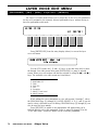
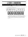
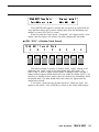
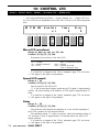
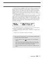
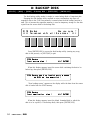
■ Selecting & Editing Parameters
Most SY85 edit screens contain several parameters that can be selected and
edited. In most cases you can simply operate the continuous slider immediately
below the parameter you want to edit on the display. Operating a slider auto-
matically moves the underline cursor to the corresponding parameter. In the
example below, for example (this is the VOICE EDIT mode Oscillator screen),
the [CS5] slider can be used to adjust the “Fine” parameter.
The parameters can also be edited by first moving the cursor to the required
parameter by pressing the corresponding function key ([F7], for example, would
select the “Rndm” parameter in the above display), and then by using either the
data entry dial or the [-1] and [+1] keys to adjust the parameter’s value.
In some special cases you’ll also use the function keys as parameter
“switches,” and the [SHIFT] key is sometimes called into play to access sec-
ondary functions. Such exceptions are described in the appropriate sections of
the manual.
GENERAL EDITING PROCEDURE
The illustrations here are not available.

11
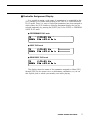
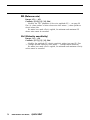
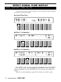
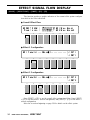
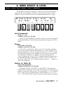
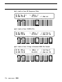
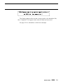
■ Controller Assignment Display
It is possible to assign a wide range of parameters to be controlled by the
[CS1] through [CS4] sliders when playing in the VOICE or PERFORMANCE
PLAY modes. Since it is easy to forget what parameters have been assigned to
which sliders, the SY85 features a controller assignment display that can be
selected temporarily by pressing the [SHIFT] key in the VOICE or PERFORM-
ANCE PLAY mode.
● PERFORMANCE PLAY mode
● VOICE PLAY mode
● DRUM VOICE PLAY mode
This display shows the names of the parameters assigned to sliders [CS1]
through [CS4] for the current voice or performance combination, so you can
take a quick peek to refresh your memory even while playing.
GENERAL EDITING PROCEDURE


PERFORMANCE EDIT MODE

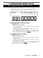
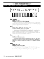
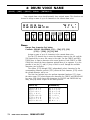
14
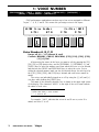
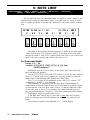
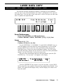
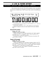
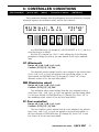
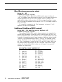
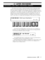
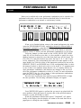
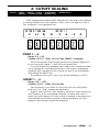
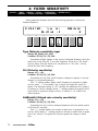
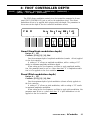
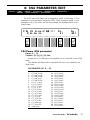
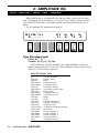
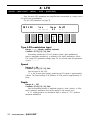
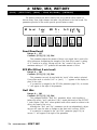
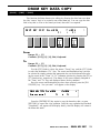
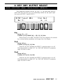
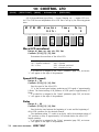
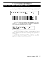
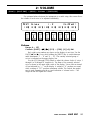
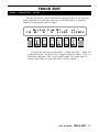
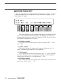
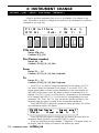
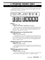
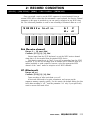
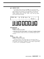
1: VOICE NUMBER
[PERFORMANCE] → [EDIT] → [MENU] → 1:Layer → [ENTER/YES] → [ENTER/YES] →
→ [MENU] → 1:Voice Number → [ENTER/YES]
SY85 performance combinations can have up to four voices assigned to different
“layers” — A, B, C and D. This screen lets you assign voices to the layers.
PERFORMANCE EDIT MODE / 1:Layer
Voice Number A, B, C, D
Range: off, A1 … H7 (internal & card)
Controls: MEMORY, GROUP, PROGRAM, [CS2], [CS4], [CS6], [CS8],
[-1] [+1], Dial
After moving the cursor to the layer you want to edit by pressing the [F2],
[F4], [F6] or [F8] function key, use the [INTERNAL 1], [INTERNAL 2], and
[CARD] keys to select the memory area from which the voice is to be selected,
and then use the GROUP and PROGRAM keys to select the voice. Voices
within the selected memory bank can also be selected directy for each layer by
the [CS2], [CS4], [CS6], and [CS8] keys. Internal and card voices cannot be
mixed.
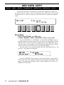
The voices can individually turned on or off by using the [-] (off) and [+]
(on) keys while holding the [SHIFT] key.
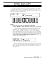
The name of the currently selected voice is shown in the upper right corner
of the display. The characters “ABCD” to the right of the voice name indicate
the status of each voice:
• Capital letter = voice on.
• Lower-case letter = voice muted.
• “-” = voice is off.
For example, “Ab-D” indicates that voices A and D are on, voice B is
muted, and voice C is off.
F1
CS1
F2
CS2
F3
CS3
F4
CS4
F5
CS5
F6
CS6
F7
CS7
F8
CS8

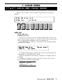
15PERFORMANCE EDIT MODE / 1:Layer
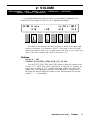
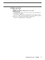
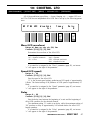
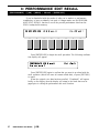
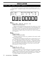
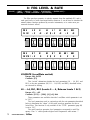
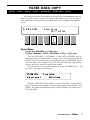
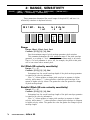
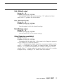
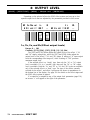
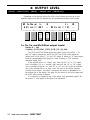
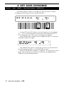
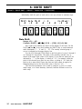
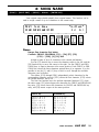
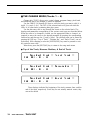
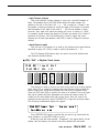
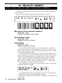
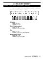
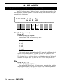
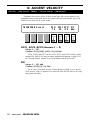
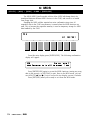
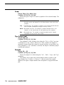
2: VOLUME
For optimum balance between the voices in a performance combination, this
screen allows the volume of each voice to be adjusted individually.
The name of the currently selected voice/layer is shown in the upper right
corner of the display. The characters “ABCD” to the right of the voice name
indicate the status of each voice: a capital letter if the voice is on, a lower-case
letter if the voice is muted, and a dash if the voice is off.
Volume
Range: 0 … 127
Controls: [CS2], [CS4], [CS6], [CS8], [-1] [+1], Dial
Use the [CS2], [CS4], [CS6], and [CS8] sliders to adjust the volume levels
of the A, B, C, and D layer voices, respectively. A setting of “0” produces no
sound, while a setting of “127” produces maximum volume. The vertical bar
graphs next to each parameter provide a visual indication of volume levels —
the longer the bar the higher the volume. Voices that are turned off are indi-
cated by “----” on the display.
[PERFORMANCE] → [EDIT] → [MENU] → 1:Layer → [ENTER/YES] → [ENTER/YES] →
→ [MENU] → 2:Volume → [ENTER/YES]
F1
CS1
F2
CS2
F3
CS3
F4
CS4
F5
CS5
F6
CS6
F7
CS7
F8
CS8

16
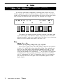
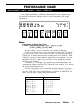
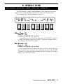
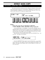
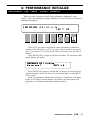
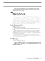
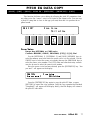
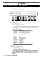
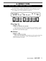
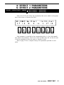
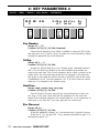
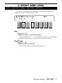
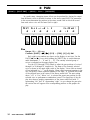
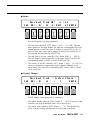
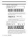
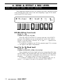
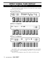
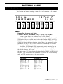
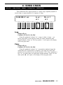
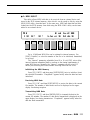
3: PAN
[PERFORMANCE] → [EDIT] → [MENU] → 1:Layer → [ENTER/YES] → [ENTER/YES] →
→ [MENU] → 3:Pan → [ENTER/YES]
In multi-layer performance combinations, interesting stereo effects can be pro-
duced by placing the output from different layers at different locations in the stereo
sound field. The parameters in this screen determine the position in the stereo sound
field in which the sound from each active layer will be heard (left to right).
PERFORMANCE EDIT MODE / 1:Layer
The name of the currently selected voice/layer is shown in the upper right
corner of the display. The characters “ABCD” to the right of the voice name
indicate the status of each voice: a capital letter if the voice is on, a lower-case
letter if the voice is muted, and a dash if the voice is off.
Pan
Range: -31 … +31
Controls: [CS2], [CS4], [CS6], [CS8], [-1] [+1], Dial
Use the [CS2], [CS4], [CS6], and [CS8] sliders to adjust the pan positions
of the A, B, C, and D layer voices, respectively. Minus values represent pan-
ning to the left, and positive values represent panning to the right. “0” posi-
tions the sound of the selected layer in the center of the stereo sound field.
Voices that are turned off are indicated by “---” on the display. The upper line
of the display also shows a graphic representation of the stereo sound field
with “L” representing “left” and “R” representing “right.” As you change the
pan value the vertical bar will appear at the corresponding position on the
graphic display.
F1
CS1
F2
CS2
F3
CS3
F4
CS4
F5
CS5
F6
CS6
F7
CS7
F8
CS8

17PERFORMANCE EDIT MODE / 1:Layer
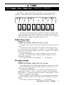
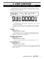
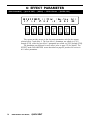
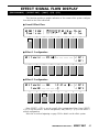
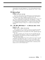
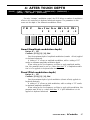
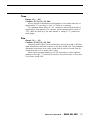
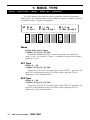
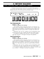
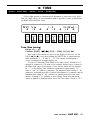
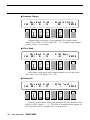
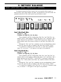
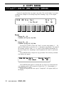
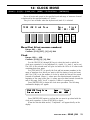
4: TUNE
More than just simple tuning, the note shift and fine tune parameters make it
possible to create harmony and voice-thickening detune effects between layers.
[PERFORMANCE] → [EDIT] → [MENU] → 1:Layer → [ENTER/YES] → [ENTER/YES] →
→ [MENU] → 4:Tune → [ENTER/YES]
The name of the currently selected voice/layer is shown in the upper right
corner of the display. The characters “ABCD” to the right of the voice name
indicate the status of each voice: a capital letter if the voice is on, a lower-case
letter if the voice is muted, and a dash if the voice is off.
NtShft (Note shift)
Range: -63 … +63
Controls: [CS1], [CS3], [CS5], [CS7], [-1] [+1], Dial
Individually shifts the pitch of each active element up or down in semitone
steps.
Use the [CS1], [CS3], [CS5], and [CS7] sliders to shift the pitch of the A,
B, C, and D layer voices, respectively. A setting of “-12,” for example, shifts
the pitch of the selected layer down by one octave; a setting of “+4” shifts the
pitch up by a major third.
The Note Shift parameter can be used to transpose a voice to its most
useful range, or to create harmony (intervals) between different layers in a
performance combination.
Voices that are turned off are indicated by “---” on the display.
Fine (Fine tuning)
Range: -7 … +7
Controls: [CS2], [CS4], [CS6], [CS8], [-1] [+1], Dial
Allows slight upward or downward pitch adjustment of each active element.
Use the [CS2], [CS4], [CS6], and [CS8] sliders to fine tune the A, B, C,
and D layer voices, respectively.
The maximum minus setting of “-7” produces a downward pitch shift of
approximately 2 cents (a “cent” is 1/100th of a semitone), and the maximum
plus setting of “+7” produces an upward pitch shift of approximately 2 cents. A
setting of “0” produces no pitch change.
The Fine parameter allows different layers in a performance combination to
be slightly detuned in relation to each other, thereby “thickening” the overall
sound.
Voices that are turned off are indicated by “--” on the display.
F1
CS1
F2
CS2
F3
CS3
F4
CS4
F5
CS5
F6
CS6
F7
CS7
F8
CS8

18
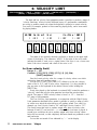
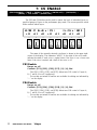
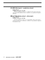
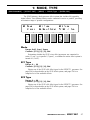
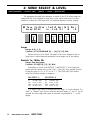
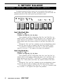
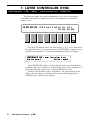
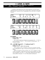
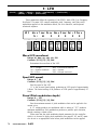
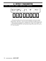
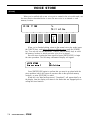
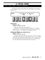
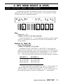
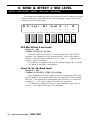
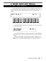
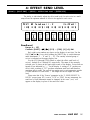
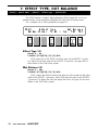
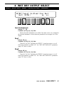
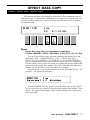
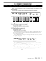
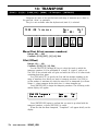
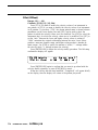
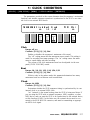
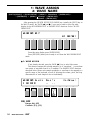
5: NOTE LIMIT
[PERFORMANCE] → [EDIT] → [MENU] → 1:Layer → [ENTER/YES] → [ENTER/YES] →
→ [MENU] → 5:Note Limit → [ENTER/YES]
The low and high note limit parameters make it possible to create a range of split
keyboard effects using the performance layers. You could have two layers on either
side of a single split point, a four-way split keyboard, or any other possible combina-
tion.
PERFORMANCE EDIT MODE / 1:Layer
The name of the currently selected voice/layer is shown in the upper right
corner of the display. The characters “ABCD” to the right of the voice name
indicate the status of each voice: a capital letter if the voice is on, a lower-case
letter if the voice is muted, and a dash if the voice is off.
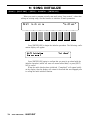
Lo (Low note limit)
Range: C-2 … G8
Controls: [CS1], [CS3], [CS5], [CS7], [-1] [+1], Dial,
[SHIFT]+keyboard
Individually sets the low note limit for each active layer (the lowest note
that each layer will produce).
Use the [CS1], [CS3], [CS5], and [CS7] sliders to set the low note limits of
the A, B, C, and D layer voices, respectively. It is also possible to press the
desired note on the keyboard while holding the [SHIFT] key.
The C-2 to G8 range of this parameter covers a full 10-1/2 octaves. “C3”
corresponds to “middle C” on a keyboard.
This parameter, in conjunction with the High Note Limit parameter de-
scribed below, allows the sound from a layer to be limited to a specific region
of the keyboard. If the Low Note Limit is set to C3 and the High Note Limit
for the same layer is set to C4, for example, the sound from that layer will
only be produced between C3 and C4 — the octave immediately above middle
C. This makes it simple to produce split voices.
If the High Note Limit is set to a note that is
lower than the Low Note
Limit for the same layer, the notes between the high and low limits will not
sound.
Voices that are turned off are indicated by “---” on the display.
F1
CS1
F2
CS2
F3
CS3
F4
CS4
F5
CS5
F6
CS6
F7
CS7
F8
CS8
≥ ≥ ≥ ≥

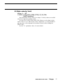
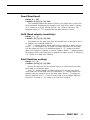
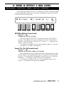
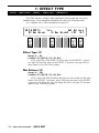
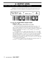
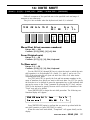
19PERFORMANCE EDIT MODE / 1:Layer
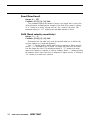
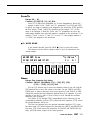
Hi (High note limit)
Range: C-2 … G8
Controls: [CS2], [CS4], [CS6], [CS8], [-1] [+1], Dial,
[SHIFT]+keyboard
Individually sets the high note limit for each active layer (the highest note
that each layer will produce).
Use the [CS2], [CS4], [CS6], and [CS8] sliders to set the high note limits
of the A, B, C, and D layer voices, respectively. It is also possible to press the
desired note on the keyboard while holding the [SHIFT] key.
See the “Lo” parameter, above, for more details.
La page charge ...
La page charge ...
La page charge ...
La page charge ...
La page charge ...
La page charge ...
La page charge ...
La page charge ...
La page charge ...
La page charge ...
La page charge ...
La page charge ...
La page charge ...
La page charge ...
La page charge ...
La page charge ...
La page charge ...
La page charge ...
La page charge ...
La page charge ...
La page charge ...
La page charge ...
La page charge ...
La page charge ...
La page charge ...
La page charge ...
La page charge ...
La page charge ...
La page charge ...
La page charge ...
La page charge ...
La page charge ...
La page charge ...
La page charge ...
La page charge ...
La page charge ...
La page charge ...
La page charge ...
La page charge ...
La page charge ...
La page charge ...
La page charge ...
La page charge ...
La page charge ...
La page charge ...
La page charge ...
La page charge ...
La page charge ...
La page charge ...
La page charge ...
La page charge ...
La page charge ...
La page charge ...
La page charge ...
La page charge ...
La page charge ...
La page charge ...
La page charge ...
La page charge ...
La page charge ...
La page charge ...
La page charge ...
La page charge ...
La page charge ...
La page charge ...
La page charge ...
La page charge ...
La page charge ...
La page charge ...
La page charge ...
La page charge ...
La page charge ...
La page charge ...
La page charge ...
La page charge ...
La page charge ...
La page charge ...
La page charge ...
La page charge ...
La page charge ...
La page charge ...
La page charge ...
La page charge ...
La page charge ...
La page charge ...
La page charge ...
La page charge ...
La page charge ...
La page charge ...
La page charge ...
La page charge ...
La page charge ...
La page charge ...
La page charge ...
La page charge ...
La page charge ...
La page charge ...
La page charge ...
La page charge ...
La page charge ...
La page charge ...
La page charge ...
La page charge ...
La page charge ...
La page charge ...
La page charge ...
La page charge ...
La page charge ...
La page charge ...
La page charge ...
La page charge ...
La page charge ...
La page charge ...
La page charge ...
La page charge ...
La page charge ...
La page charge ...
La page charge ...
La page charge ...
La page charge ...
La page charge ...
La page charge ...
La page charge ...
La page charge ...
La page charge ...
La page charge ...
La page charge ...
La page charge ...
La page charge ...
La page charge ...
La page charge ...
La page charge ...
La page charge ...
La page charge ...
La page charge ...
La page charge ...
La page charge ...
La page charge ...
La page charge ...
La page charge ...
La page charge ...
La page charge ...
La page charge ...
La page charge ...
La page charge ...
La page charge ...
La page charge ...
La page charge ...
La page charge ...
La page charge ...
La page charge ...
La page charge ...
La page charge ...
La page charge ...
La page charge ...
La page charge ...
La page charge ...
La page charge ...
La page charge ...
La page charge ...
La page charge ...
La page charge ...
La page charge ...
La page charge ...
La page charge ...
La page charge ...
La page charge ...
La page charge ...
La page charge ...
La page charge ...
La page charge ...
La page charge ...
La page charge ...
La page charge ...
La page charge ...
La page charge ...
La page charge ...
La page charge ...
La page charge ...
La page charge ...
La page charge ...
La page charge ...
La page charge ...
La page charge ...
La page charge ...
La page charge ...
La page charge ...
La page charge ...
La page charge ...
La page charge ...
La page charge ...
La page charge ...
La page charge ...
La page charge ...
La page charge ...
La page charge ...
La page charge ...
La page charge ...
La page charge ...
La page charge ...
La page charge ...
La page charge ...
La page charge ...
La page charge ...
La page charge ...
La page charge ...
La page charge ...
La page charge ...
La page charge ...
La page charge ...
La page charge ...
La page charge ...
La page charge ...
La page charge ...
La page charge ...
La page charge ...
La page charge ...
La page charge ...
La page charge ...
La page charge ...
La page charge ...
La page charge ...
La page charge ...
La page charge ...
La page charge ...
La page charge ...
La page charge ...
La page charge ...
La page charge ...
La page charge ...
La page charge ...
La page charge ...
La page charge ...
La page charge ...
La page charge ...
La page charge ...
La page charge ...
La page charge ...
La page charge ...
La page charge ...
La page charge ...
La page charge ...
La page charge ...
La page charge ...
La page charge ...
La page charge ...
La page charge ...
La page charge ...
La page charge ...
La page charge ...
La page charge ...
La page charge ...
La page charge ...
La page charge ...
La page charge ...
La page charge ...
La page charge ...
La page charge ...
La page charge ...
La page charge ...
La page charge ...
La page charge ...
La page charge ...
La page charge ...
La page charge ...
La page charge ...
La page charge ...
La page charge ...
La page charge ...
La page charge ...
La page charge ...
La page charge ...
La page charge ...
La page charge ...
La page charge ...
La page charge ...
La page charge ...
La page charge ...
La page charge ...
La page charge ...
La page charge ...
La page charge ...
La page charge ...
La page charge ...
La page charge ...
La page charge ...
La page charge ...
La page charge ...
La page charge ...
La page charge ...
La page charge ...
La page charge ...
La page charge ...
La page charge ...
La page charge ...
La page charge ...
La page charge ...
La page charge ...
La page charge ...
La page charge ...
La page charge ...
La page charge ...
La page charge ...
La page charge ...
La page charge ...
La page charge ...
La page charge ...
La page charge ...
La page charge ...
La page charge ...
La page charge ...
-
 1
1
-
 2
2
-
 3
3
-
 4
4
-
 5
5
-
 6
6
-
 7
7
-
 8
8
-
 9
9
-
 10
10
-
 11
11
-
 12
12
-
 13
13
-
 14
14
-
 15
15
-
 16
16
-
 17
17
-
 18
18
-
 19
19
-
 20
20
-
 21
21
-
 22
22
-
 23
23
-
 24
24
-
 25
25
-
 26
26
-
 27
27
-
 28
28
-
 29
29
-
 30
30
-
 31
31
-
 32
32
-
 33
33
-
 34
34
-
 35
35
-
 36
36
-
 37
37
-
 38
38
-
 39
39
-
 40
40
-
 41
41
-
 42
42
-
 43
43
-
 44
44
-
 45
45
-
 46
46
-
 47
47
-
 48
48
-
 49
49
-
 50
50
-
 51
51
-
 52
52
-
 53
53
-
 54
54
-
 55
55
-
 56
56
-
 57
57
-
 58
58
-
 59
59
-
 60
60
-
 61
61
-
 62
62
-
 63
63
-
 64
64
-
 65
65
-
 66
66
-
 67
67
-
 68
68
-
 69
69
-
 70
70
-
 71
71
-
 72
72
-
 73
73
-
 74
74
-
 75
75
-
 76
76
-
 77
77
-
 78
78
-
 79
79
-
 80
80
-
 81
81
-
 82
82
-
 83
83
-
 84
84
-
 85
85
-
 86
86
-
 87
87
-
 88
88
-
 89
89
-
 90
90
-
 91
91
-
 92
92
-
 93
93
-
 94
94
-
 95
95
-
 96
96
-
 97
97
-
 98
98
-
 99
99
-
 100
100
-
 101
101
-
 102
102
-
 103
103
-
 104
104
-
 105
105
-
 106
106
-
 107
107
-
 108
108
-
 109
109
-
 110
110
-
 111
111
-
 112
112
-
 113
113
-
 114
114
-
 115
115
-
 116
116
-
 117
117
-
 118
118
-
 119
119
-
 120
120
-
 121
121
-
 122
122
-
 123
123
-
 124
124
-
 125
125
-
 126
126
-
 127
127
-
 128
128
-
 129
129
-
 130
130
-
 131
131
-
 132
132
-
 133
133
-
 134
134
-
 135
135
-
 136
136
-
 137
137
-
 138
138
-
 139
139
-
 140
140
-
 141
141
-
 142
142
-
 143
143
-
 144
144
-
 145
145
-
 146
146
-
 147
147
-
 148
148
-
 149
149
-
 150
150
-
 151
151
-
 152
152
-
 153
153
-
 154
154
-
 155
155
-
 156
156
-
 157
157
-
 158
158
-
 159
159
-
 160
160
-
 161
161
-
 162
162
-
 163
163
-
 164
164
-
 165
165
-
 166
166
-
 167
167
-
 168
168
-
 169
169
-
 170
170
-
 171
171
-
 172
172
-
 173
173
-
 174
174
-
 175
175
-
 176
176
-
 177
177
-
 178
178
-
 179
179
-
 180
180
-
 181
181
-
 182
182
-
 183
183
-
 184
184
-
 185
185
-
 186
186
-
 187
187
-
 188
188
-
 189
189
-
 190
190
-
 191
191
-
 192
192
-
 193
193
-
 194
194
-
 195
195
-
 196
196
-
 197
197
-
 198
198
-
 199
199
-
 200
200
-
 201
201
-
 202
202
-
 203
203
-
 204
204
-
 205
205
-
 206
206
-
 207
207
-
 208
208
-
 209
209
-
 210
210
-
 211
211
-
 212
212
-
 213
213
-
 214
214
-
 215
215
-
 216
216
-
 217
217
-
 218
218
-
 219
219
-
 220
220
-
 221
221
-
 222
222
-
 223
223
-
 224
224
-
 225
225
-
 226
226
-
 227
227
-
 228
228
-
 229
229
-
 230
230
-
 231
231
-
 232
232
-
 233
233
-
 234
234
-
 235
235
-
 236
236
-
 237
237
-
 238
238
-
 239
239
-
 240
240
-
 241
241
-
 242
242
-
 243
243
-
 244
244
-
 245
245
-
 246
246
-
 247
247
-
 248
248
-
 249
249
-
 250
250
-
 251
251
-
 252
252
-
 253
253
-
 254
254
-
 255
255
-
 256
256
-
 257
257
-
 258
258
-
 259
259
-
 260
260
-
 261
261
-
 262
262
-
 263
263
-
 264
264
-
 265
265
-
 266
266
-
 267
267
-
 268
268
-
 269
269
-
 270
270
-
 271
271
-
 272
272
-
 273
273
-
 274
274
-
 275
275
-
 276
276
-
 277
277
-
 278
278
-
 279
279
-
 280
280
-
 281
281
-
 282
282
-
 283
283
-
 284
284
-
 285
285
-
 286
286
-
 287
287
-
 288
288
-
 289
289
-
 290
290
-
 291
291
-
 292
292
-
 293
293
-
 294
294
-
 295
295
-
 296
296
-
 297
297
-
 298
298
-
 299
299
-
 300
300
-
 301
301
-
 302
302
-
 303
303
-
 304
304
-
 305
305
-
 306
306
-
 307
307
-
 308
308
-
 309
309
-
 310
310
-
 311
311
-
 312
312
-
 313
313
-
 314
314
-
 315
315
-
 316
316
-
 317
317
-
 318
318
-
 319
319
-
 320
320
-
 321
321
-
 322
322
-
 323
323
-
 324
324
-
 325
325
-
 326
326
-
 327
327
-
 328
328
-
 329
329
-
 330
330
-
 331
331


Yamaha SY85 Manuel utilisateur
- Catégorie
- Instruments de musique
- Taper
- Manuel utilisateur
dans d''autres langues
- italiano: Yamaha SY85 Manuale utente
- English: Yamaha SY85 User manual
- español: Yamaha SY85 Manual de usuario
- Deutsch: Yamaha SY85 Benutzerhandbuch
- русский: Yamaha SY85 Руководство пользователя
- Nederlands: Yamaha SY85 Handleiding
- português: Yamaha SY85 Manual do usuário
- dansk: Yamaha SY85 Brugermanual
- polski: Yamaha SY85 Instrukcja obsługi
- čeština: Yamaha SY85 Uživatelský manuál
- svenska: Yamaha SY85 Användarmanual
- Türkçe: Yamaha SY85 Kullanım kılavuzu
- suomi: Yamaha SY85 Ohjekirja
- română: Yamaha SY85 Manual de utilizare
Documents connexes
-
Yamaha SY85 Le manuel du propriétaire
-
-
-
Yamaha MOTIF6 Manuel utilisateur
-
-
-
-
Yamaha MOTIF ES8 Manuel utilisateur
-
Yamaha S80 Manuel utilisateur
-