
MagicLock ML22FOX
DE 6 Zentralverriegelung VW FOX
Montageanleitung
EN 12 Central locking system VW FOX
Installation Manual
FR 18 Verrouillage centralisé VW FOX
Instructions de montage
ES 24
Cierre centralizado VW FOX
Instrucciones de montaje
IT 30 Chiusura centralizzata VW FOX
Istruzioni di montaggio
NL 36 Centrale vergrendeling VW FOX
Montagehandleiding
DA 42 Centrallås VW FOX
Monteringsvejledning
SV 48 Centrallås VW FOX
Monteringsanvisning
NO 53 Sentrallås VW FOX
Monteringsanvisning
FI 59 Keskuslukitus VW FOX
Asennusohje
ML-22-FOX.book Seite 1 Mittwoch, 15. März 2006 3:40 15

D
Fordern Sie weitere Informationen zur umfangreichen Produktpalette aus dem Hause
WAECO an. Bestellen Sie einfach unsere Kataloge kostenlos und unverbindlich unter
der Internetadresse: www.waeco.de
GB
We will be happy to provide you with further information about WAECO products.
Please order our free catalogue with no obligation to buy on our homepage:
www.waeco.com
F
Demandez d’autres informations relatives à la large gamme de produits de la maison
WAECO. Commandez tout simplement notre catalogue gratuitement et sans
engagement à l’adresse internet suivante : www.waeco.com
E
Solicite más información sobre la amplia gama de productos de la empresa WAECO.
Solicite simplemente nuestros catálogos de forma gratuita y sin compromiso en la
dirección de Internet: www.waeco.com
I
Per ottenere maggiori informazioni sull’ampia gamma di prodotti WAECO è possibile
ordinare una copia gratuita e non vincolante del nostro Catalogo all’indirizzo Internet:
www.waeco.com
NL
Maak kennis met het omvangrijke productscala van de firma WAECO. Bestel onze
catalogus gratis en vrijblijvend onder het internetadres: www.waeco.com
DK
Bestil yderligere information om det omfattende produktudvalg fra WAECO.
Bestil vores katalog gratis og uforpligtende på internetadressen: www.waeco.com
S
Inhämta mer information om den omfattande produktpaletten från WAECO:
Beställ våra kataloger gratis och utan förpliktelser under vår Internetadress:
www.waeco.com
N
Be om mer informasjon om det rikholdige produktutvalget fra WAECO. Bestill vår
katalog gratis uforbindtlig på Internettadressen: www.waeco.com
FIN
Pyytäkää lisää tietoja WAECOn kattavista tuotevalikoimista. Tilatkaa tuotekuvastomme
maksutta ja sitoumuksetta internet-osoitteesta: www.waeco.com
ML-22-FOX.book Seite 2 Mittwoch, 15. März 2006 3:40 15

MagicLock ML22FOX
3
2 3
4 5
1
8
3
3
6
2
7
4
5
1
ML-22-FOX.book Seite 3 Mittwoch, 15. März 2006 3:40 15

MagicLock ML22FOX
4
0
8 9
6
7
a
b
ML-22-FOX.book Seite 4 Mittwoch, 15. März 2006 3:40 15

MagicLock ML22FOX
5
c
d
ML-22-FOX.book Seite 5 Mittwoch, 15. März 2006 3:40 15

Sicherheits- und Einbauhinweise MagicLock ML22FOX
6
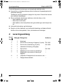
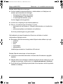
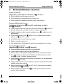
Inhaltsverzeichnis
1 Sicherheits- und Einbauhinweise. . . . . . . . . . . . . . . . . . . . . . . . . . . 6
2 Lieferumfang . . . . . . . . . . . . . . . . . . . . . . . . . . . . . . . . . . . . . . . . . . 8
3 Bestimmungsgemäßer Gebrauch . . . . . . . . . . . . . . . . . . . . . . . . . . 9
4 Zentralverriegelung montieren . . . . . . . . . . . . . . . . . . . . . . . . . . . . . 9
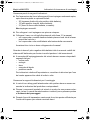
1 Sicherheits- und Einbauhinweise
Achtung!
WAECO übernimmt keine Haftung für Schäden aufgrund folgen-
der Punkte:
– Montagefehler,
– Beschädigungen am Gerät durch mechanische Einflüsse und
Überspannungen,
– Veränderungen am Gerät ohne ausdrücklicher Genehmigung
von WAECO,
– Verwendung für andere als die in der Anleitung beschriebenen
Zwecke.
Warnung!
Klemmen Sie wegen der Kurzschlussgefahr vor Arbeiten an der
Fahrzeugelektrik immer den Minuspol ab.
Bei Fahrzeugen mit Zusatzbatterie müssen Sie an dieser eben-
falls den Minuspol abklemmen.
Warnung!
Unzureichende Leitungsverbindungen können zur Folge haben,
dass durch Kurzschluss
– Kabelbrände entstehen,
– der Airbag ausgelöst wird,
– elektronische Steuerungseinrichtungen beschädigt werden,
– elektrische Funktionen ausfallen (Blinker, Bremslicht, Hupe,
Zündung, Licht).
ML-22-FOX.book Seite 6 Mittwoch, 15. März 2006 3:40 15

MagicLock ML22FOX Sicherheits- und Einbauhinweise
7
Beachten Sie deshalb folgende Hinweise:
z Verwenden Sie bei Arbeiten an den folgenden Leitungen nur isolierte
Kabelschuhe, Stecker und Flachsteckhülsen.
– 30 (Eingang von Batterie Plus direkt),
– 15 (Geschaltetes Plus, hinter Batterie),
– 31 (Rückleitung ab Batterie, Masse).
Verwenden Sie keine Lüsterklemmen.
z Verwenden Sie eine Krimpzange zum Verbinden der Kabel.
z Schrauben Sie das Kabel bei Anschlüssen an Leitung 31 (Masse)
– mit Kabelschuh und Zahnscheibe an eine fahrzeugeigene Masse-
schraube oder
– mit Kabelschuh und Blechschraube an das Karosserieblech.
Achten Sie auf eine gute Masseübertragung!
Beim Abklemmen des Minuspols der Batterie verlieren alle flüchtigen
Speicher der Komfortelektronik ihre gespeicherten Daten.
z Folgende Daten müssen Sie je nach Fahrzeugausstattung neu einstellen:
– Radiocode
– Fahrzeuguhr
– Zeitschaltuhr
– Bordcomputer
– Sitzposition
Hinweise zur Einstellung finden Sie in der jeweiligen Bedienungs-
anleitung ihres Fahrzeugs.
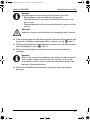
Beachten Sie folgende Hinweise bei der Montage:
z Bei Fahrzeugen mit Seitenairbags in den Türen sind die entsprechenden
Herstellerangaben des zu beachten.
z Befestigen Sie die im Fahrzeug montierten Teile so, dass sie sich unter
keinen Umständen (scharfes Abbremsen, Verkehrsunfall) lösen und zu
Verletzungen der Fahrzeuginsassen führen können.
z Achten Sie beim Bohren auf ausreichenden Freiraum für den Bohrer-
austritt, um Schäden zu vermeiden.
ML-22-FOX.book Seite 7 Mittwoch, 15. März 2006 3:40 15

Lieferumfang MagicLock ML22FOX
8
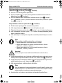
Beachten Sie folgende Hinweise bei der Arbeit an elektrischen Teilen:
z Benutzen Sie zum Prüfen der Spannung in elektrischen Leitungen nur
eine Diodenprüflampe oder ein Voltmeter.
Prüflampen mit einem Leuchtkörper nehmen zu hohe Ströme auf, wo-
durch die Fahrzeugelektronik beschädigt werden kann.
z Beachten Sie beim Verlegen der elektrischen Anschlüsse, dass diese
– nicht geknickt oder verdreht werden,
– nicht an Kanten scheuern,
– nicht ohne Schutz durch scharfkantige Durchführungen verlegt
werden.
z Isolieren Sie alle Verbindungen und Anschlüsse.
z Sichern Sie die Kabel gegen mechanische Beanspruchung durch Kabel-
binder oder Isolierband, z. B. an vorhandenen Leitungen.
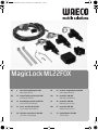
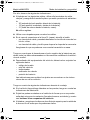
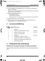
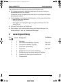
2Lieferumfang
Nr. in
Abb. 1
Menge Bezeichnung
Artikel-
Nr.
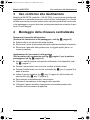
1 1 Kabelsatz –
2 1 Stellmotor Heckklappenverriegelung (2-polig) ML-3602
3 2 Stellmotor Türverriegelung (5-polig) ML-3605
4 1 Schließeinheit Heckklappenverriegelung –
5 1 Steuergerät ML-3061
6 2 Metallhaken für Stellmotor Türverriegelung –
7 1 Metallhaken für Stellmotor
Heckklappenverriegelung
–
8 2 Lochbleche zur Befestigung Stellmotor Tür –
– 1 Befestigungsmaterial –
ML-22-FOX.book Seite 8 Mittwoch, 15. März 2006 3:40 15

MagicLock ML22FOX Bestimmungsgemäßer Gebrauch
9
3 Bestimmungsgemäßer Gebrauch
MagicLock ML22FOX (Model No. ML-22-FOX) ist eine Zentralverriegelung
zum Nachrüsten für Fahrzeuge des Typs Volkswagen Fox. Durch den Ein-
satz von Stellmotoren werden beim Verschließen der Fahrer- oder Beifahrer-
tür automatisch beide Türen und die Heckklappe verriegelt.
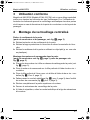
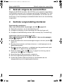
4 Zentralverriegelung montieren
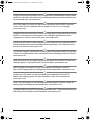
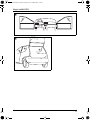
Türverkleidung entfernen
(Fahrer- und Beifahrertür, siehe Abb. 2, Seite 3)
➤ Drehen Sie alle Schrauben der Türverkleidung heraus.
➤ Entfernen Sie den Sicherungsring der Fensterkurbel und nehmen Sie die
Kurbel ab.
➤ Entfernen Sie die Türverkleidung mit einem flachen Gegenstand (z. B.
Kunststoffkeil).
Anbringen der Stellmotoren in der Tür
(Fahrertür siehe Abb. 4, Seite 3, Beifahrertür siehe Abb. 5, Seite 3)
➤ Stecken Sie die Blechmuttern über die vorhandenen Bohrungen in der
Tür (siehe Abb. 3, Seite 3).
➤ Befestigen Sie den Stellmotor mit zwei Schrauben + Unterlegscheiben
am Lochblech.
➤ Befestigen Sie mit zwei Schrauben + Unterlegscheiben das Lochblech
(Abb. 1, Pos. 8, Seite 3) an der Blechmutter.
➤ Fädeln Sie den Metallhaken (Abb. 1, Pos. 6, Seite 3) in die Öse des
Stellmotors (Abb. 1, Pos. 3, Seite 3).
➤ Fahren Sie den Hub des Stellmotors komplett ein.
➤ Schließen Sie den Verriegelungsmechanismus der Tür.
➤ Verbinden Sie den Metallhaken mit Hilfe des Klemmblocks am Gestänge
des Öffnungsmechanismusses.
ML-22-FOX.book Seite 9 Mittwoch, 15. März 2006 3:40 15

Zentralverriegelung montieren MagicLock ML22FOX
10
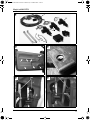
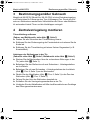
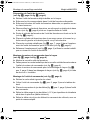
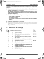
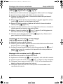
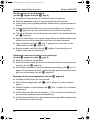
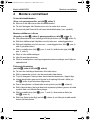
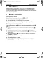
Vorbereitung der Schließeinheit
(siehe Abb. 6, Seite 4 bis Abb. 9, Seite 4)
➤ Entfernen Sie die werkseitige Schließeinheit der Heckklappe.
➤ Stecken Sie den passenden Schlüssel in die ausgebaute Schließeinheit.
➤ Drücken Sie den Knopf der ausgebauten Schließeinheit in geöffneter
Stellung in das Schloss.
➤ Entriegeln Sie den Schließzylinder, indem Sie einen spitzen Gegenstand
in die Bohrung (siehe Abb. 6, Seite 4) auf der rechten Seite der Einheit
eindrücken.
➤ Ziehen Sie den werkseitigen Schließzylinder am Schlüssel aus der
Schließeinheit (siehe Abb. 7, Seite 4).
➤ Stecken Sie den Schließzylinder in die neue Verriegelung und lassen Sie
den Zylinder durch mehrmaliges Hin- und Herdrehen des Schlüssels ein-
rasten.
➤ Legen Sie den Metallhaken (Abb. 1, Pos. 7, Seite 3) in die Aufnahme
der Schließeinheit (siehe Abb. 8, Seite 4).
➤ Klappen Sie die Aufnahme fest zu (siehe Abb. 9, Seite 4) und befesti-
gen Sie so den Metallhaken an der Schließeinheit.
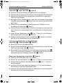
Anbringen des Stellmotors in der Heckklappe
(siehe Abb. 0, Seite 4 und Abb. a, Seite 4)
➤ Bauen Sie die neue Schließeinheit ein.
➤ Fädeln Sie den Metallhaken an der neuen Schließeinheit in die Öse des
Stellmotors ein (siehe Abb. 0, Seite 4).
➤ Schrauben Sie den Stellmotor für die Heckklappenverriegelung (Abb. 1,
Pos. 2, Seite 3) mit zwei Schrauben + Unterlegscheiben an die vorhande-
nen Bohrungen der Heckklappe (siehe Abb. b, Seite 4).
Einbau des Steuergerätes (siehe Abb. b, Seite 4)
➤ Entfernen Sie die Klappe links vom Lenkrad.
➤ Kleben Sie das Steuergerät (Abb. 1, Pos. 5, Seite 3) unter die Armatur.
➤ Stecken Sie den Stecker des Kabelsatzes (Abb. 1, Pos. 1, Seite 3) in
das Steuergerät.
➤ Verbinden Sie das rote Kabel am Kabelsatz (+ 12 V) mit dem Batterie-
Klemmbock im Fußraum (Spritzwand innen).
➤ Verbinden Sie das schwarze Kabel am Kabelsatz mit einem geeigneten
Massepunkt an der Fahrzeugkarosserie.
ML-22-FOX.book Seite 10 Mittwoch, 15. März 2006 3:40 15

MagicLock ML22FOX Zentralverriegelung montieren
11
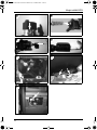
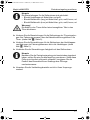
Hinweis
Die Steuerleitungen für die Stellmotoren sind gebündelt:
– Bündel Heckklappe mit Kabel blau und grün
– Bündel Beifahrertür (lang) mit Kabel blau, grün, weiß, braun, rot
– Bündel Beifahrertür (kurz) mit Kabel blau, grün, weiß, braun, rot
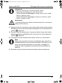
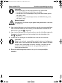
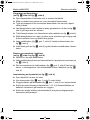
Warnung!
Die Kabel in den Türen dürfen keine beweglichen Teile in den
Türen blockieren.
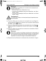
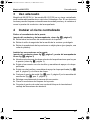
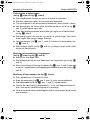
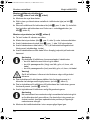
➤ Verlegen Sie die Steuerleitungen für die Stellmotoren der Türverriegelun-
gen vom Fahrzeuginnenraum über die Kabeldurchführungstüllen in die
Türen. (siehe Abb. c, Seite 5).
➤ Verlegen Sie die Steuerleitungen für die Stellmotoren der Heckklappen-
verriegelungen im Fahrzeuginnenraum bis in die Heckklappe. (siehe
Abb. d, Seite 5).
➤ Verbinden Sie die Steuerleitungen farbgleich mit den Stellmotoren.
Hinweis
Nachdem Sie die Zentralverriegelung wie beschrieben eingebaut
haben, sollten Sie eine Funktionsprüfung vornehmen. Sollte diese
Prüfung nicht sofort erfolgreich verlaufen, korrigieren Sie die
Position des Klemmblocks am Gestänge des Öffnungs-
mechanismusses.
➤ Versetzen Sie alle Verkleidungsbauteile zurück in Ihren Ursprungs-
zustand.
ML-22-FOX.book Seite 11 Mittwoch, 15. März 2006 3:40 15

Safety and installation instructions MagicLock ML22FOX
12
Contents
1 Safety and installation instructions. . . . . . . . . . . . . . . . . . . . . . . . . 12
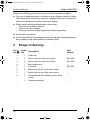
2 Scope of delivery . . . . . . . . . . . . . . . . . . . . . . . . . . . . . . . . . . . . . . 14
3 Intended use . . . . . . . . . . . . . . . . . . . . . . . . . . . . . . . . . . . . . . . . . 15
4 Fitting the central locking system. . . . . . . . . . . . . . . . . . . . . . . . . . 15
1 Safety and installation instructions
Note
WAECO will not be held liable for damage resulting from the
following:
– Installation errors
– Damage to the appliance resulting from mechanical influences
and excess voltage
– Alterations to the device without express permission from
WAECO
– Use for purposes other than those described in the operating
manual
Warning
To prevent the risk of short circuits, always disconnect the nega-
tive terminal of the vehicle's electrical system before working on it.
If the vehicle has an additional battery, its negative terminal
should also be disconnected.
Warning
Inadequate supply cable connections could result in short circuits,
which could have as a consequence that:
– cable fires occur
– The airbag being triggered
– Damage to electronic control equipment
– Electrical malfunctions (indicators, brake light, horn, ignition,
lights)
ML-22-FOX.book Seite 12 Mittwoch, 15. März 2006 3:40 15

MagicLock ML22FOX Safety and installation instructions
13
Please observe the following instructions:
z When working on the following lines, only use insulated cable lugs, plugs
and sleeves.
– 30 (direct supply from positive battery terminal)
– 15 (connected positive terminal, behind the battery)
– 31 (return line from the battery, earth).
Do not use terminal strips.
z Use a crimping tool to connect the cables.
z Screw the cable for connections to wire 31 (earth)
– Screw on the cable using a cable lug and serrated washer with one of
the vehicle's earth bolts
– Screw the cable to the bodywork using a cable lug and a self-tapping
screw
Ensure that there is a good earth connection.
If you disconnect the negative terminal of the battery, all data stored in the
volatile memories will be lost.
z The following data must be set again, depending on the vehicle equip-
ment options:
– radio code
– vehicle clock
–Timer
– On-board computer
– Seat position
You can find instructions on making these settings in the owner's manual
of your vehicle.
Observe the following installation instructions:
z Note the manufacturer's instructions if the vehicle has side airbags in the
doors.
z Secure the parts installed in the vehicle in such a way that they cannot be-
come loose under any circumstances (sudden braking, accidents) and
cause injuries to the occupants of the vehicle.
z To prevent damage when drilling make sure there is sufficient space on
the other side for the drill head to come out.
ML-22-FOX.book Seite 13 Mittwoch, 15. März 2006 3:40 15

Scope of delivery MagicLock ML22FOX
14
Observe the following instructions when working with electrical parts:
z Only use a diode test lamp or voltmeter to test voltages in electric cables.
Test lamps with an illuminant consume voltages which are too high and
which can damage the vehicle's electronic system.
z When making electrical connections, ensure that:
– They are not kinked or twisted
– They do not rub on edges
– They are not laid in sharp-edged ducts without protection
z Insulate all connections.
z Protect the cables from mechanical wear (for example rubbing against ex-
isting cables) using cable binders or insulating tape.
2 Scope of delivery
No. in
fig. 1
Quan-
tity
Description
Item
number
11Cable set –
2 1 Servo motor for boot lock (2-pin) ML-3602
3 2 Servo motor for door lock (5-pin) ML-3605
4 1 Boot locking unit –
5 1 Controller ML-3061
6 2 Metal hook for door lock servo motor –
7 1 Metal hook for boot lock servo motor –
8 2 Perforated plate for fastening door servo
motor
–
– 1 Fastening material –
ML-22-FOX.book Seite 14 Mittwoch, 15. März 2006 3:40 15

MagicLock ML22FOX Intended use
15
3 Intended use
The MagicLock ML22FOX (model no. ML-22-FOX) is a central locking
system for fitting in Volkswagen Fox vehicles. It has servo motors which
automatically lock both doors and the boot when the driver or passenger door
is locked.
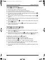
4 Fitting the central locking system
Removing the door panelling
(Driver and passenger door, see fig. 2, page 3)
➤ Unscrew all the panelling screws.
➤ Remove the retaining ring of the window winder and take off the winder.
➤ Remove the door panelling with a flat object such as a plastic wedge.
Fitting the servo motor in the door
(Driver door see fig. 4, page 3, passenger door see fig. 5, page 3)
➤ Push the plate nuts over the existing holes in the door (see fig. 3,
page 3).
➤ Fasten the servo motor to the perforated plate using two bolts and wash-
ers.
➤ Using two bolts and washers, fasten the perforated plate (fig. 1, Pos. 8,
page 3) to the plate nut.
➤ Attach the metal hook (fig. 1, 6, page 3) to the eyelet of the servo motor
(fig. 1, 3, page 3).
➤ Completely retract the servo motor.
➤ Close the door locking mechanism.
➤ Connect the metal hook to the linkage of the opening mechanism using
the terminal block.
ML-22-FOX.book Seite 15 Mittwoch, 15. März 2006 3:40 15

Fitting the central locking system MagicLock ML22FOX
16
Preparing the locking unit
(see fig. 6, page 4 to fig. 9, page 4)
➤ Remove the original locking unit in the boot.
➤ Put the matching key into the detached locking unit.
➤ Press the button of the removed locking unit with the lock open.
➤ Release the cylinder by pushing a pointed object into the hole (see fig. 6,
page 4) on the right side of the unit.
➤ Using the key, pull the original cylinder out of the locking unit (see fig. 7,
page 4).
➤ Put the cylinder into the new lock and turn the key back and forth until the
cylinder latches in place.
➤ Place the metal hook (fig. 1, 7, page 3) in the holder of the locking unit
(see fig. 8, page 4).
➤ Tightly close the holder (see fig. 9, page 4) thus fastening the metal
hook to the locking unit.
Attaching the servo motor to the boot
(see fig. 0, page 4 and fig. a, page 4)
➤ Install the new locking unit.
➤ Attach the metal hook of the new locking unit to the eyelet of the servo
motor (see fig. 0, page 4).
➤ Fasten the boot lock servo motor (fig. 1, 2, page 3) using two bolts and
washers to the existing holes in the boot hatch (see fig. b, page 4).
Installing the controller (see fig. b, page 4)
➤ Remove the flap to the left of the steering wheel.
➤ Stick the controller (fig. 1, 5, page 3) under the dashboard.
➤ Plug the cable set (fig. 1, Pos. 1, page 3) into the controller.
➤ Connect the red cable on the cable set (+12 V) to the battery terminal
block in the footwell (inside splashguard).
➤ Connect the black cable on the cable set to a suitable earth point on the
bodywork.
ML-22-FOX.book Seite 16 Mittwoch, 15. März 2006 3:40 15

MagicLock ML22FOX Fitting the central locking system
17
Note
The control wires for the servo motors are bunched together:
– Boot set: blue and green cables
– Passenger door set (long): blue, green, white, brown and red
cables
– Passenger door set (short): blue, green, white, brown and red
cables
Warning
The cables in the doors may not block any moving parts.
➤ Lay the control wires for the door lock servo motors from the interior of the
vehicle via the cable ducts into the doors. (see fig. c, page 5).
➤ Lay the control wires for the boot lock servo motors from the vehicle inte-
rior to the boot. (see fig. d, page 5).
➤ Connect the control wires to the matching colours on the servo motors.
Note
After you have installed the central locking system as described,
check that it works properly. If this test is not successful, adjust
the position of the terminal block on the linkage of the opening
mechanism.
➤ Put all panelling back where it was originally.
ML-22-FOX.book Seite 17 Mittwoch, 15. März 2006 3:40 15

Consignes de sécurité et instructions de montage MagicLock ML22FOX
18
Table des matières
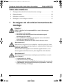
1 Consignes de sécurité et instructions de montage . . . . . . . . . . . . 18
2 Pièces fournies . . . . . . . . . . . . . . . . . . . . . . . . . . . . . . . . . . . . . . . 20
3 Utilisation conforme . . . . . . . . . . . . . . . . . . . . . . . . . . . . . . . . . . . . 21
4 Montage du verrouillage centralisé . . . . . . . . . . . . . . . . . . . . . . . . 21
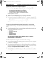
1 Consignes de sécurité et instructions de
montage
Attention !
WAECO décline toute responsabilité en cas de dommages
causés par :
– des erreurs de montage,
– des influences mécaniques et des surtensions ayant
endommagé le matériel,
– des modifications apportées à l'appareil sans autorisation
explicite de la part de WAECO,
– une utilisation différente de celle décrite dans la notice.
Avertissement !
Débranchez toujours la borne négative avant de procéder à des
travaux sur les éléments électriques du véhicule afin d’éviter tout
risque de court-circuit.
Sur les véhicules équipés d’une batterie supplémentaire, vous
devez également débrancher le pôle négatif de cette dernière.
Avertissement !
Tout branchement électrique inadéquat peut entraîner un court-
circuit causant
– la combustion de câbles,
– le déclenchement de l'airbag,
– l’endommagement des dispositifs électroniques de commande,
– la défaillance des fonctions électriques (clignotants, feux-stop,
klaxon, allumage, éclairage).
ML-22-FOX.book Seite 18 Mittwoch, 15. März 2006 3:40 15

MagicLock ML22FOX Consignes de sécurité et instructions de montage
19
Veuillez donc respecter les consignes suivantes :
z Pour tous les travaux sur les lignes électriques suivantes, n’utilisez que
des cosses de câble, fiches et alvéoles pour contacts plats isolés :
– 30 (entrée directe pôle positif de la batterie),
– 15 (pôle positif connecté, derrière la batterie),
– 31 (ligne de retour à partir de la batterie, masse).
N’utilisez pas de dominos.
z Utilisez une pince de sertissage pour raccorder les câbles.
z Pour les raccordements à la ligne électrique 31 (masse), vissez le câble
– à une vis de masse du véhicule, avec une cosse et une rondelle cran-
tée, ou bien
– à la carrosserie, avec une cosse et une vis à tôle.
Veillez à une bonne transmission de la masse !
Lorsque vous débranchez le pôle négatif de la batterie, les mémoires
volatiles de l’électronique de confort perdent toutes les données enregis-
trées.
z Vous devez procéder à un nouveau réglage des données suivantes en
fonction de l’équipement du véhicule :
– code radio
– horloge du véhicule
– minuterie
– ordinateur de bord
– position du siège
Les instructions de réglage figurent dans les notices d’utilisation
correspondantes de votre véhicule.
Veuillez respecter les consignes suivantes lors du montage :
z Pour les véhicules disposant d'airbags latéraux dans les portes, respecter
les données du fabricant.
z Fixez les pièces installées dans le véhicule de manière à ce qu’elles ne
puissent en aucun cas se desserrer (freinage abrupt, accident) et risquer
de causer des blessures aux occupants du véhicule.
z Avant de percer des trous, assurez-vous que vous disposez d’un espace
suffisant de l'autre côté du trou à percer afin que la mèche n'occasionne
aucun dégât.
ML-22-FOX.book Seite 19 Mittwoch, 15. März 2006 3:40 15

Pièces fournies MagicLock ML22FOX
20
Veuillez respecter les consignes suivantes pour les travaux sur les éléments
électriques :
z Pour contrôler la tension des lignes électriques, n’utilisez qu’une lampe
étalon à diodes ou un voltmètre.
Les lampes étalons à corps lumineux absorbent des courants trop élevés
qui pourraient endommager les systèmes électroniques du véhicule.
z Lors de l'installation des raccordements électriques, veillez à ce que
ceux-ci
– ne soient ni pliés, ni tordus,
– ne frottent pas contre des arêtes,
– ne soient pas placés dans des passages à arêtes vives sans
protection.
z Isolez toutes les connexions et tous les raccords.
z Protégez les câbles contre toute contrainte mécanique en les fixant par
exemple aux lignes existantes à l'aide de serre-câbles ou de ruban vinyle.
2 Pièces fournies
N° dans
fig. 1
Quantité Désignation
N°
d'article
1 1 Jeu de câbles –
2 1 Moteur de commande verrouillage hayon
(2 pôles)
ML-3602
3 2 Moteur de commande verrouillage porte
(5 pôles)
ML-3605
4 1 Unité de fermeture verrouillage hayon –
5 1 Unité de commande ML-3061
6 2 Crochet métallique pour le moteur de
commande du verrouillage porte
–
7 1 Crochet métallique pour le moteur de
commande du verrouillage hayon
–
8 2 Tôles perforées pour la fixation moteur de
commande porte
–
– 1 Matériel de fixation –
ML-22-FOX.book Seite 20 Mittwoch, 15. März 2006 3:40 15
La page charge ...
La page charge ...
La page charge ...
La page charge ...
La page charge ...
La page charge ...
La page charge ...
La page charge ...
La page charge ...
La page charge ...
La page charge ...
La page charge ...
La page charge ...
La page charge ...
La page charge ...
La page charge ...
La page charge ...
La page charge ...
La page charge ...
La page charge ...
La page charge ...
La page charge ...
La page charge ...
La page charge ...
La page charge ...
La page charge ...
La page charge ...
La page charge ...
La page charge ...
La page charge ...
La page charge ...
La page charge ...
La page charge ...
La page charge ...
La page charge ...
La page charge ...
La page charge ...
La page charge ...
La page charge ...
La page charge ...
La page charge ...
La page charge ...
La page charge ...
La page charge ...
-
 1
1
-
 2
2
-
 3
3
-
 4
4
-
 5
5
-
 6
6
-
 7
7
-
 8
8
-
 9
9
-
 10
10
-
 11
11
-
 12
12
-
 13
13
-
 14
14
-
 15
15
-
 16
16
-
 17
17
-
 18
18
-
 19
19
-
 20
20
-
 21
21
-
 22
22
-
 23
23
-
 24
24
-
 25
25
-
 26
26
-
 27
27
-
 28
28
-
 29
29
-
 30
30
-
 31
31
-
 32
32
-
 33
33
-
 34
34
-
 35
35
-
 36
36
-
 37
37
-
 38
38
-
 39
39
-
 40
40
-
 41
41
-
 42
42
-
 43
43
-
 44
44
-
 45
45
-
 46
46
-
 47
47
-
 48
48
-
 49
49
-
 50
50
-
 51
51
-
 52
52
-
 53
53
-
 54
54
-
 55
55
-
 56
56
-
 57
57
-
 58
58
-
 59
59
-
 60
60
-
 61
61
-
 62
62
-
 63
63
-
 64
64


Waeco MagicLock ML-22-FOX Guide d'installation
- Taper
- Guide d'installation
- Ce manuel convient également à
dans d''autres langues
Documents connexes
-
Waeco Waeco PC-200-12 Mode d'emploi
-
-
-
-
-
-
-
Waeco MagicWatch MWE-150-2DIS Mode d'emploi
-