Yes ZNAE42DS Manuel utilisateur
- Catégorie
- Hottes
- Taper
- Manuel utilisateur

WWW.ZEPHYRONLINE.COM
NOV20.0101
Airflow Control Technology
TM
C
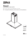
Napoli
ZNA-M90DS, ZNA-E42DS
EN Use, Care, and Installation Guide
FR Guide d’utilisation, d’entretien et d’installation

2
Napoli Use, Care, and Installation Guide
NAPOLI
ISLAND
CORE

3
Napoli Use, Care, and Installation Guide
ZEPHYRONLINE.COM
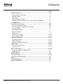
Contents
Page
Safety Information ............................................................................ 4-6
Types of Safety Warnings ................................................................... 4
General Safety ..................................................................................4-5
Operation ........................................................................................... 6
Electrical Requirements ...................................................................... 6
Federal Communication Commission Interface Statement ................. 6
List of Materials ................................................................................... 7
Installation Instructions .................................................................... 8-20
Ducting Calculation Sheet .................................................................. 8
Mounting Height, Clearance, & Ducting ...........................................9-10
Ducting Options .................................................................................11
Hood Specifications ............................................................................12
Electrical Supply .................................................................................13
Cable Lock .........................................................................................13
Mounting the Hood .......................................................................... 14-18
Ductless Recirculation .....................................................................19-20
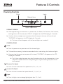
Features & Controls ..........................................................................21-27
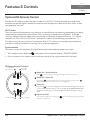
Proximity Controls ...........................................................................21-23
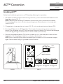
Zephyr Connect ..............................................................................24-25
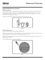
Optional RF Remote Control ............................................................26-27
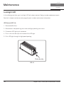
Maintenance ................................................................................... 28-30
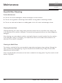
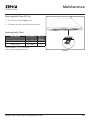
Hood & Filter Cleaning .....................................................................28-29
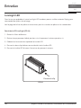
LumiLight LED ................................................................................... 30
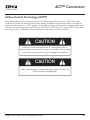
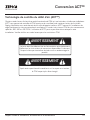
ACT™ Conversion .............................................................................31-32
Airflow Control Technology (ACT™) ....................................................31
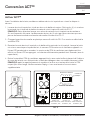
Enabling ACT™ .................................................................................. 32
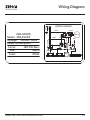
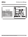
Wiring Diagram ..................................................................................33
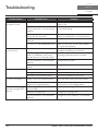
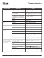
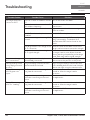
Troubleshooting............................................................................... 34-36
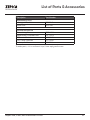
List of Parts & Accessories .................................................................. 37
Notes ..................................................................................................38
Limited Warranty ...............................................................................39
Product Registration ...........................................................................40

4
Napoli Use, Care, and Installation Guide
NAPOLI
ISLAND
CORE
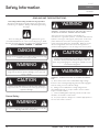
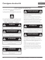
Safety Information
Your safety and the safety of others are very important.
We have provided many important safety messages in this
manual for your appliance. Always read and obey all safety
messages.
This is the Safety Alert Symbol. This symbol alerts you to
potential hazards that can cause severe bodily injury or death.
All safety messages will follow the Safety Alert Symbol and either
the words “DANGER” “WARNING” or “CAUTION”
DANGER
Danger means that failure to heed this safety statement may
result in severe injury or death.
READ AND SAVE THESE INSTRUCTIONS
WARNING - TO REDUCE THE RISK OF FIRE, ELECTRIC SHOCK,
OR INJURY TO PERSONS, OBSERVE THE FOLLOWING:
a) Use this unit only in the manner intended by the
manufacturer. If you have questions, contact the manufacturer.
b) Before servicing or cleaning unit, switch power o at service
panel and lock the service disconnecting means to prevent
power from being switched on accidentally. When the service
disconnecting means cannot be locked, securely fasten a
prominent warning device, such as a tag, to the service panel.
General Safety
WARNING
Warning means that failure to heed this safety statement
may result in extensive product damage, serious personal
injury, or death.
CAUTION
Caution means that failure to heed this safety statement
may result in minor or moderate personal injury, property or
equipment damage.
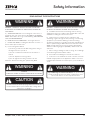
WARNING
To reduce the risk of fire or electric shock, do not use this fan
with any solid-state control device.
WARNING
CAUTION
For General Ventilating Use Only. Do Not Use To Exhaust
Hazardous Or Explosive Materials And Vapors. Take care
when using cleaning agents or detergents. Suitable for use in
household cooking area.
WARNING
WARNING - TO REDUCE THE RISK OF A RANGE TOP GREASE
FIRE:
a) Never leave surface units unattended at high settings.
Boilovers cause smoking and greasy spillovers that may ignite.
Heat oils slowly on low or medium settings.
b) Always turn hood ON when cooking at high heat or
when flambeing food. (i.e. Crepes Suzette, Cherries Jubilee,
Peppercorn Beef Flambe’).
c) Clean ventilating fans frequently. Grease should not be
allowed to accumulate on fan or filter.
d) Use proper pan size. Always use cookware appropriate for
the size of the surface element.

5
Napoli Use, Care, and Installation Guide
ZEPHYRONLINE.COM
Safety Information
WARNING
READ AND SAVE THESE INSTRUCTIONS
WARNING - TO REDUCE THE RISK OF INJURY TO PERSONS
IN THE EVENT OF A RANGE TOP GREASE FIRE, OBSERVE THE
FOLLOWING:
a) SMOTHER FLAMES with a close-fitting lid, cookie sheet, or
metal tray, then turn o the burner. BE CAREFUL TO PREVENT
BURNS. If the flames do not go out immediately, EVACUATE AND
CALL THE FIRE DEPARTMENT.
b) NEVER PICK UP A FLAMING PAN – You may be burned.
c) DO NOT USE WATER, including wet dishcloths or towels – a
violent steam explosion will result.
d) Use an extinguisher ONLY if:
1) You know you have a Class ABC extinguisher, and you
already know how to operate it.
2) The fire is small and contained in the area where it
started.
3) The fire department is being called.
4) You can fight the fire with your back to an exit
Based on “Kitchen Firesafety Tips” published by NFPA.
WARNING
WARNING
TO REDUCE THE RISK OF FIRE, USE ONLY METAL DUCTWORK.
CAUTION
To reduce risk of fire and to properly exhaust air outside, do
not vent exhaust air into spaces within walls, ceilings, attics,
crawl spaces, or garages.
WARNING
WARNING - TO REDUCE THE RISK OF FIRE, ELECTRIC SHOCK,
OR INJURY TO PERSONS, OBSERVE THE FOLLOWING:
a) Installation work and electrical wiring must be done by
qualified person(s) in accordance with all applicable codes and
standards, including fire-rated construction.
b) Sucient air is needed for proper combustion and
exhausting of gases through the flue (chimney) of fuel burning
equipment to prevent back drafting. Follow the heating
equipment manufacturer’s guideline and safety standards such
as those published by the National Fire Protection Association
(NFPA), and the American Society for Heating, Refrigeration
and Air Conditioning Engineers (ASHRAE), and the local code
authorities.
c) When cutting or drilling into wall or ceiling, do not damage
electrical wiring and other hidden utilities.
d) Ducted fans must always be vented to the outdoors.
e) If this unit is to be installed over a tub or shower, it must be
marked as appropriate for the application and be connected
to a GFCI (Ground Fault Circuit Interrupter) - protected branch
circuit.
WARNING
Prop. 65 Warning for California Residents: This product may
contain chemicals known to the State of California to cause
cancer, birth defects, or other reproductive harm.

6
Napoli Use, Care, and Installation Guide
NAPOLI
ISLAND
CORE
Safety Information
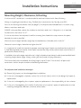
Operation
Ź Always leave safety grilles and filters in place. Without these components, operating blowers could catch onto hair, fingers and
loose clothing.
Ź The manufacturer declines all responsibility in the event of failure to observe the instructions given here for installation,
maintenance and suitable use of the product. The manufacturer further declines all responsibility for injury due to negligence and
the warranty of the unit automatically expires due to improper maintenance.
NOTE: Please check www.zephyronline.com for revisions before doing any custom work.
Electrical Requirements
Important:
Ź Observe all governing codes and ordinances.
Ź It is the customer’s responsibility to be aware of these below:
Ź To contact a qualified electrical installer.
Ź To assure that the electrical installation is adequate and in conformance with National Electrical Code, ANSI/NFPA 70 latest
edition* or CSA standards C22.1-94, Canadian Electrical Code, Part 1 and C22.2 No.0-M91 - latest edition** and all local codes
and ordinances.
Ź If codes permit and a separate ground wire is used, it is recommended that a qualified electrician determine that the ground path
is adequate.
Ź Do not ground to a gas pipe.
Ź Check with a qualified electrician if you are not sure the range hood is properly grounded.
Ź Do not have a fuse in the neutral or ground circuit.
Ź This appliance requires a 120V 60Hz electrical supply and connected to an individual properly grounded branch circuit protected
by a 15 or 20 ampere circuit breaker or time delay fuse. Wiring must be 2 wire with ground. Please also refer to Electrical Diagram
on product.
Ź A cable locking connector (not supplied) might also be required by local codes. Check with local requirements, purchase and
install appropriate connector if necessary.
* National Fire Protection Association Batterymarch Park, Quincy, Massachusetts 02269
** CSA International 8501 East Pleasant Valley Road, Cleveland, Ohio 44131-5575
Federal Communication Commission Interface Statement
Ź This equipment has been tested and found to comply with the limits for a Class B digital device, pursuant to Part 15 of the FCC
Rules. These limits are designed to provide reasonable protection against harmful interference in a residential installation.
Ź This equipment generates, uses and can radiate radio frequency energy and, if not installed and used in accordance with the
instructions, may cause harmful interference to radio communications. However, there is no guarantee that interference will not
occur in a particular installation. If this equipment does cause harmful interference to radio or television reception, which can be
determined by turning the equipment o and on, the user is encouraged to try to correct the interference by one of the following
measures:
Ź Reorient or relocate the receiving antenna.
Ź Increase the separation between the equipment and receiver.
Ź Connect the equipment into an outlet on a circuit dierent from that to which the receiver is connected.
Ź Consult the dealer or an experienced radio/TV technician for help.
READ AND SAVE THESE INSTRUCTIONS

7
Napoli Use, Care, and Installation Guide
ZEPHYRONLINE.COM
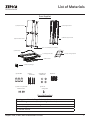
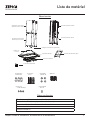
List of Materials
(3) Wire Nuts
(4) ø12 OD / ø5
ID Washers
(4) #6 x 1”
wood srews
(4) 3/16 x 1/4” pan-head
machine screws
(1) Hardware package
(1) 8” round damper (pre-installed)
(2) Top Duct Covers
(1) Top Support Frame
(2) Bottom Duct Covers
(1) Bottom Support Frame
(1) Hood Body
(4) LumiLight LED, 6W
(2) Bae Filters
(1) M4 x 12
safety screw
A
B
Front of Hood
C
L
/
Cut-Out Shaded Area
(1) Paper ceiling template
(8) M4 x 8
Parts Not Supplied
Ducting, conduit and all installation tools
Cable locking connector (if required by local codes)
Duct cover extension accessory
Recirculating kit
RF remote control
Parts Supplied

8
Napoli Use, Care, and Installation Guide
NAPOLI
ISLAND
CORE
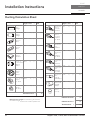
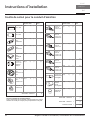
Installation Instructions
Duct pieces
To t al
Equivalent number
length x used =
3- 1/ 4” x 10”
Rect.,
straight
1 Ft. x ( ) =
Ft.
3- 1/ 4” x 10”
Rect. to
6” round
transition
5 Ft. x ( ) =
Ft.
3- 1/ 4” x 10”
Rect. to
6” round
transition
90
0
elbow
20 Ft. x ( ) =
Ft.
6”, 7”, 8”, 10”
Round,
90
0
15 Ft.
x ( ) =
Ft.
6”, 7”, 8”, 10”
Round,
45
0
9 Ft. x ( ) =
Ft.
Ft.
6”, 7”, 8”, 10”
Round,
straight
1 Ft. x ( ) =
Ft.
Subtotal column 1 =
Duct pieces
To t al
Equivalent number
length x used =
6”, 7”, 8”, 10”
Round, wall
cap with
damper
30 Ft. x ( ) =
Ft.
Ft.
Ft.
Ft.
6”, 7”, 8”, 10”
Round
roof cap
30 Ft. x ( ) =
Ft.
Subtotal column 2 =
Subtotal column 1 =
Total ductwork =
Maximum Duct Length: For satisfactory air movement,
the total duct length
should not exceed 150 equivalent feet.
6” round to
3- 1/ 4” x 10”
rect.
transition
1 Ft. x ( ) =
Ft.
6” round to
3- 1/ 4” x 10”
rect.
transition
90
0
elbow
16 Ft. x ( ) =
Ft.
7” round to
3 1/ 4” x 10”
rect.
transition
8 Ft. x ( ) =
Ft.
7” round to
3- 1/ 4” x 10”
rect.
transition
90
0
elbow
23 Ft. x ( ) =
Ft.
elbow
elbow
7” to 6” or
8” to 7” Round
tapered
reducer
25 Ft. x ( ) =
Ft.
3- 1/ 4” x 10”
Rect. 90
0
elbow
15 Ft. x ( ) =
Ft.
3- 1/ 4” x 10”
Rect. 45
0
elbow
9 Ft. x ( ) =
Ft.
3- 1/ 4” x 10”
Rect. 90
0
flat elbow
24 Ft. x ( ) =
Ft.
3- 1/ 4” x 10”
Rect.
wall cap
with damper
30 Ft. x ( ) =
Ft.
Ft. x ( ) =
Ft.
15
6”, 7“, 8”
Round
in-line
damper
Ducting Calculation Sheet

9
Napoli Use, Care, and Installation Guide
ZEPHYRONLINE.COM
Installation Instructions
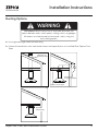
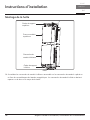
Mounting Height, Clearance, & Ducting
min. A
min. B
max. C
Standard Extension
Hood Heights Duct Cover Duct Cover
minimum ducted (A) 32” 49“
minimum recirculating (B) 36-
1/2” 53-1/2“
maximum (C) 50” 80”
Ceiling Heights
minimum ducted (D) 92” (7’ 8”) 109“ (9’ 1”)
minimum recirculating (E) 96
1/2” (8’ 1/2”) 113 1/2“ (9’5-1/2”)
maximum (F) 120” (10’) 150” (12’ 6”)
36”
24” min.
34” max.
min. D
min. E
max. F

10
Napoli Use, Care, and Installation Guide
NAPOLI
ISLAND
CORE
Installation Instructions
Mounting Height, Clearance, & Ducting
A minimum of 8” round duct is recommended to maintain maximum air flow eciency.
Always use rigid type metal ducts only. Flexible ducts could restrict air flow by up to 50%.
Also use the ducting calculation sheet (on page 11) to compute total available duct run when using
elbows, transitions and caps.
ALWAYS, when possible, reduce the number or transitions and turns. If long duct run is required,
increase duct size from 8” to 10”.
If turns or transitions are required; install as far away from hood duct output and as far apart,
between the two as possible.
Minimum mount height between range top to hood bottom should be no less than 24”.
Maximum mount height should be no higher than 34”.
It is important to install the hood at the proper mounting height. Hoods mounted too low could result
in heat damage and fire hazard; while hoods mounted too high will be hard to reach and will lose its
performance and eciency.
If available, also refer range manufacturer’s height clearance requirements and recommended hood
mounting height above range. Always check your local codes for any dierences.
Duct cover extension kit available for ceiling heights up to 12 feet. Turn to the list of parts and
accessories section for part number and ordering information.
For shipment and installation damages:
Ź Please fully inspect unit for damage before installation.
Ź If the unit is damaged in shipment, return the unit to the store in which it was bought for repair or
replacement.
Ź If the unit is damaged by the customer, repair or replacement is the responsibility of the customer.
Ź If the unit is damaged by the installer (if other than the customer), repair of replacement must be
made by arrangement between customer and installer.

11
Napoli Use, Care, and Installation Guide
ZEPHYRONLINE.COM
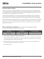
Installation Instructions
Ducting Options
Ź Use single wall rigid metal ductwork only.
Ź Fasten all connections with sheet metal screws and tape all joints w/ certified Silver Tape or Duct
Tape.
Fire Hazard: NEVER exhaust air or terminate ductwork into
spaces between walls, crawl spaces, ceilings, attics, or garages.
All exhaust must be ducted to the outside, unless using the
recirculating option.
WARNING
Sot or crawl space
Roof Pitch w/
Flashing & Cap
side wall cap
w/ gravity damper
ductless
recirculating

12
Napoli Use, Care, and Installation Guide
NAPOLI
ISLAND
CORE
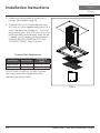
Installation Instructions
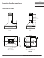
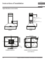
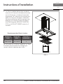
Ů
FRONT SIDE
TOP of HOOD TOP SUPPORT FRAME
(top view)
1-1/8”
5-5/16”
STANDARD
min. ducted- 32”
min. recirc. - 36-
1/2”
max. - 50”
Z1C-02NA
min. ducted - 49”
min. recirc. - 53-
1/2”
max. - 80”
9-13/16”
25-
9/16”
12-13/16”
35-
7/16”, 41-15/16”
13-1/8”
10-
5/16”
7-
13/16
”
7/8”
Elec. KO
C/L
C/L
4-13/16”
9/16”
FRONT
10-1/16”
10-
1/14”
C/L
4-3/14”
6-3/4”
6-1/2”

13
Napoli Use, Care, and Installation Guide
ZEPHYRONLINE.COM
Installation Instructions
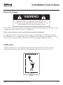
Electrical Supply
Electrical wiring must be done by qualified person(s) in
accordance with all applicable codes and standards. Turn o
electrical power at service entrance before wiring.
WARNING
For personal safety, remove house fuse or open circuit breaker before beginning installation. Do not
use extension cord or adapter plug with this appliance.
Follow national electrical codes or prevailing local codes and ordinances.
This appliance requires a 120V 60Hz electrical supply, and connected to an individual, properly
grounded branch circuit, protected by a 15 or 20 ampere circuit breaker or time delay fuse. Wiring
must be 2 wire w/ ground. Please also refer to the Electrical Diagram labeled on product.
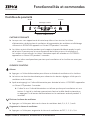
Cable Lock
A cable locking connector (not supplied) might be required by local codes. Check with local
requirements and codes, purchase and install appropriate connector if necessary. (FIG. A)
Cable Lock
FIG. A

14
Napoli Use, Care, and Installation Guide
NAPOLI
ISLAND
CORE
Installation Instructions
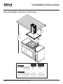
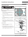
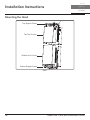
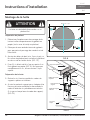
Mounting the Hood
Ceiling Preparation
1. Determine hood mounting location and
temporarily tape paper template (included with
the hood) to the ceiling.
2. Cut-out internal shaded area of template
to allow the ducting and electrical to pass
through.
3. Add wood blocking (min. 2” x 4”) onto ceiling
joists to reinforce ceiling above the drywall.
(FIG. C1).
4. Secure (2) #6 x 1” wood screws into points A
and B of the paper template (FIG. B). Do not
completely tighten screws, leave approximately
1/4” exposed.
Hood Preparation
5. Remove screws securing top and bottom
support frames together.
6. Adjust support frame to accommodate the
desired hood height and re-assemble the frame
using the previously removed screws (2 screws
for each support frame arm). (FIG. C2).
1
2
Ceiling Joists
Wood Blocking
Top Support Frame
Support Frame Arm
Bottom Support Frame
Hood Body
3
Mounting Screws
(pre-installed)
4
FIG. C
Hood is intended to be mounted to a finished
ceiling.
CAUTION
XP022220
A
B
Cut-Out Shaded Area
FIG. B
Front of Hood

15
Napoli Use, Care, and Installation Guide
ZEPHYRONLINE.COM
Installation Instructions
Mounting the Hood
FIG. D

16
Napoli Use, Care, and Installation Guide
NAPOLI
ISLAND
CORE
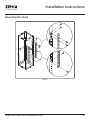
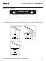
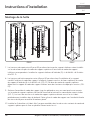
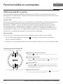
7. Hood heights between 40” to 50” require lateral support brackets to be installed to the two top
support frame cut o arms and their corresponding bottom support frame arms. Install lateral
support brackets by (12) M4 x 8 sheet metal screws shown in FIG. D.
8. Hood heights between 45” to 50” require a square support bracket to be installed inside the
support frame. Install square support bracket to top support frame arms by (8) M4 x 8 sheet metal
screws. (FIG. E1) Top support frame arms extend past lower support frame bracket with shorter
hood heights. (FIG. E2).
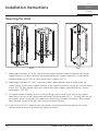
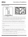
9. Lift support frame assembly up to the ceiling making sure the word “front” on the top support
frame faces the front of the hood where the controls will be located (FIG. F). The key-holes on the
top support frame should cover the wood screws previously installed in the ceiling. Slide support
frame towards narrow end of key-holes to lock the frame in place.
10. Install the last (2) #6 x 1” wood screws with washers into the two remaining corners of the top
support frame to secure it to the ceiling. Tighten all screws.
Installation Instructions
Mounting the Hood
FRONT
FRONT
FIG. E
FIG. F
12

17
Napoli Use, Care, and Installation Guide
ZEPHYRONLINE.COM
Installation Instructions
Mounting the Hood
FIG. G
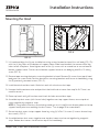
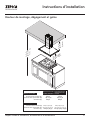
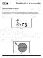
11. Lift hood and align the (4) pre-installed mounting screws located on top of the unit body (FIG. C4)
with the (4) key holes on the bottom of support frame. Slide hood towards the narrow end of key
holes to lock into place. Hand tighten each of the (4) screws with a screwdriver to secure hood to
bottom support frame. Further secure bottom support frame to unit body by one M4 x 12 safety
screw (FIG. H).
12. Remove tape securing electronics mounting bracket to hood. Remove (3) screws from top of hood
body and set screws aside. Position electronics mounting brackets and secure to hood body using
the (3) previously removed screws (FIG. G).
13. Install electrical and duct work. Seal duct work with aluminum duct tape.
14. Unwrap the blue antenna wire and position it behind the duct cover from step 16-18. There is no
need to secure it.
15. Power up hood, verify all functions and check for leaks around duct tape.
16. Assemble top duct covers (with louver holes) together over top support frame, secure top duct
covers together by magnetic strips.
NOTE: If using hood in ductless recirculating mode you must install the air diverter plate to the top
support frame prior to assembling the duct covers. Turn to page 19 for more details.
17. Secure top duct covers to top support frame by using (4) 3/16 x 1/4 screws (2 screws for each top
duct cover). (FIG. I1).
18. Assemble bottom duct covers together over top duct covers and secure together by magnetic
strips. Bottom duct covers should rest on top of the hood body.
FIG. H

18
Napoli Use, Care, and Installation Guide
NAPOLI
ISLAND
CORE
Installation Instructions
Mounting the Hood
1
Top Duct Covers
Top Support Frame
Bottom Duct Covers
Bottom Support Frame
FIG. I

19
Napoli Use, Care, and Installation Guide
ZEPHYRONLINE.COM
Installation Instructions
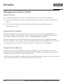
Ductless Recirculation
Ductless recirculation is intended for applications where an exhaust duct work is not possible to be
installed. When converted, the hood functions as a recirculating hood rather than an exhaust hood.
Fumes and exhaust from cooking are drawn and filtered by a set of optional charcoal filters. The air is
then purified and re-circulated back within the home.
We recommend to ALWAYS exhaust air outside of the home by employing existing or installing new
duct work, if possible. The hood is most eective and ecient as an exhaust hood. Only when the
exhaust option is not possible should you recourse to converting the hood into a recirculating hood.
When converted to be a recirculating hood, a set of charcoal filters are required on top of its standard
Metal Filter set. Order according to its part number below. The standard mesh filters are intended to
capture residue from cooking, and the optional charcoal filters help to purify fumes exhausted from
cooking for recirculation.
Recirculating Kit Installation (required if no ducting is used)
Kit includes the charcoal filters and the air diverter plate.
Hood Model Part Number Filters in Package
ZNA-M90DS ZRC-03NA 2
ZNA-E42DS ZRC-03NA 2
1. Purchase recirculating kit per the part number above.
2. Secure air diverter plate to top support frame (FIG. J). Open sides of air diverter plate should face
left and right to direct air through the louver holes located on the top duct cover. Run 8” ducting
from top of hood and secure to air diverter plate.
3. Remove bae filters from hood. Plate the charcoal filters to the back side of the bae filters.
Secure the charcoal filters in place with rubber clips.
4. Reinstall bae filters.

20
Napoli Use, Care, and Installation Guide
NAPOLI
ISLAND
CORE
Installation Instructions
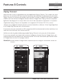
5. Enable recirculating mode on the proximity
controls. (Refer details to pg. 23)
6. Charcoal filters must be replaced after every
200 hours of use (or approximately every 3 to 6
months based on the average of 1 - 2 hours of
daily cooking time). After 200 hours of use, the
notification bell icon will display. When the bell
is tapped, the LCD display will cycle between
showing “REPLACE CHARCOAL FLTR” and
“HOLD UP TO RESET” every 2 seconds.
Charcoal Filter Replacements
Hood Model Part Number
Quantity to
Order
ZNA-M90DS Z0F-C005 2
ZNA-E42DS Z0F-C005 2
DO NOT WASH CHARCOAL FILTERS. Charcoal
filters may need to be changed more often
depending on cooking habits.
Clip
Clip
FIG. J
La page est en cours de chargement...
La page est en cours de chargement...
La page est en cours de chargement...
La page est en cours de chargement...
La page est en cours de chargement...
La page est en cours de chargement...
La page est en cours de chargement...
La page est en cours de chargement...
La page est en cours de chargement...
La page est en cours de chargement...
La page est en cours de chargement...
La page est en cours de chargement...
La page est en cours de chargement...
La page est en cours de chargement...
La page est en cours de chargement...
La page est en cours de chargement...
La page est en cours de chargement...
La page est en cours de chargement...
La page est en cours de chargement...
La page est en cours de chargement...
La page est en cours de chargement...
La page est en cours de chargement...
La page est en cours de chargement...
La page est en cours de chargement...
La page est en cours de chargement...
La page est en cours de chargement...
La page est en cours de chargement...
La page est en cours de chargement...
La page est en cours de chargement...
La page est en cours de chargement...
La page est en cours de chargement...
La page est en cours de chargement...
La page est en cours de chargement...
La page est en cours de chargement...
La page est en cours de chargement...
La page est en cours de chargement...
La page est en cours de chargement...
La page est en cours de chargement...
La page est en cours de chargement...
La page est en cours de chargement...
La page est en cours de chargement...
La page est en cours de chargement...
La page est en cours de chargement...
La page est en cours de chargement...
La page est en cours de chargement...
La page est en cours de chargement...
La page est en cours de chargement...
La page est en cours de chargement...
La page est en cours de chargement...
La page est en cours de chargement...
La page est en cours de chargement...
La page est en cours de chargement...
La page est en cours de chargement...
La page est en cours de chargement...
La page est en cours de chargement...
La page est en cours de chargement...
La page est en cours de chargement...
La page est en cours de chargement...
La page est en cours de chargement...
La page est en cours de chargement...
-
 1
1
-
 2
2
-
 3
3
-
 4
4
-
 5
5
-
 6
6
-
 7
7
-
 8
8
-
 9
9
-
 10
10
-
 11
11
-
 12
12
-
 13
13
-
 14
14
-
 15
15
-
 16
16
-
 17
17
-
 18
18
-
 19
19
-
 20
20
-
 21
21
-
 22
22
-
 23
23
-
 24
24
-
 25
25
-
 26
26
-
 27
27
-
 28
28
-
 29
29
-
 30
30
-
 31
31
-
 32
32
-
 33
33
-
 34
34
-
 35
35
-
 36
36
-
 37
37
-
 38
38
-
 39
39
-
 40
40
-
 41
41
-
 42
42
-
 43
43
-
 44
44
-
 45
45
-
 46
46
-
 47
47
-
 48
48
-
 49
49
-
 50
50
-
 51
51
-
 52
52
-
 53
53
-
 54
54
-
 55
55
-
 56
56
-
 57
57
-
 58
58
-
 59
59
-
 60
60
-
 61
61
-
 62
62
-
 63
63
-
 64
64
-
 65
65
-
 66
66
-
 67
67
-
 68
68
-
 69
69
-
 70
70
-
 71
71
-
 72
72
-
 73
73
-
 74
74
-
 75
75
-
 76
76
-
 77
77
-
 78
78
-
 79
79
-
 80
80


Yes ZNAE42DS Manuel utilisateur
- Catégorie
- Hottes
- Taper
- Manuel utilisateur
dans d''autres langues
- English: Yes ZNAE42DS User manual
Documents connexes
Autres documents
-
Zephyr ZNA-E42BS Guide d'installation
-
-
-
-
Essentials Napoli ZNA-M90CS Le manuel du propriétaire
-
-
-
-
Zephyr AK9334BS Guide d'installation
-
Zephyr AK9240BS Manuel utilisateur