Lumination RLB Series Gen 2 LED Strip Retrofit Luminaire Guide d'installation
- Taper
- Guide d'installation

LED.com
© 2023 Current Lighting Solutions, LLC. All rights reserved. Information and specifications subject to change
without notice. All values are design or typical values when measured under laboratory conditions.
Page 1 of 4
(Rev 05/22/23)
IND452-Lumination-RLB-Series-Gen-2-LED-Strip-Retrofit-Luminaire-Installation-Guide
WARNING/AVERTISSEMENT
RISK OF ELECTRIC SHOCK
• Turn power o before inspection, installation or removal.
• Properly ground electrical enclosure.
• Luminaire wiring and electrical parts may be damaged when drilling
for installation of LED retrot kit. Check for enclosed wiring and
components.
• LED Retrot Kit installation requires knowledge of luminaires
electrical systems. If not qualied, do not attempt installation.
Contact a qualied electrician.
• Install this kit only in the luminaires that have the construction
features and dimensions shown in the photographs and/or drawings
and where the input rating of the retrot kit does not exceed the
input rating of the luminaire.
• To prevent wiring damage or abrasion, do not expose wiring to
edges of sheet metal or other sharp objects.
• Do not make or alter any open holes in an enclosure of wiring or
electrical components during kit installation.
RISK OF FIRE
• Follow all NEC and local codes.
• Use only UL approved wire for input/output connections. Minimum
size 18 AWG or 14 AWG for continuous runs.
RISQUES DE DÉCHARGES ÉLECTRIQUES
• Coupez l’alimentation avant d’’inspecter, installer ou déplacer le
luminaire.
• Assurez-vous de correctement mettre à la terre le boîtier
d’alimentation lectrique.
• Le câblage du luminaire ainsi que ses composantes électriques
peuvent être endommagés lors du perçage requis pour l’installation
de l’ensemble de mise à niveau à DEL. Vériez le câblage et les
composants.
• L’installation de l’ensemble de mise à niveau à DEL requiert des
connaissances en système électrique d’éclairage. Si vous n’avez
pas les qualications adéquates, ne procédez pas à l’installation et
contactez un électricien qualié.
• N’installez cet ensemble de mise à niveau que dans des luminaires
ayant les caractéristiques de construction et les dimensions
indiquées dans les photographies et / ou dessins. La puissance
d’entrée de l’ensemble de mise à niveau ne doit pas excéder la
puissance d’entrée nominale du luminaire dans lequel l est installé.
• An de prévenir tout dommage ou abrasion aux ls électriques,
évitez que ceux-ci ne viennent en contact avec les bordures
métalliques ou d’autres ojets pointus.
• Seules les ouvertures indiquées sur les photos et dessins peuvent
être faites ou modiées lors de l’installation de l’ensemble de mise à
niveau à DEL.
RISQUES D’INCENDIE
• Respectez tous les codes NEC et codes locaux.
• N’utilisez que des ls approuvés par UL pour les entrées/ sorties de
connexion. Taille minimum 18 AWG ou 14 AWG pour les rangées
continues.
Installation Guide
LED Luminaires
RetTM Strip Fixture Retrot Series (RLB2 Series)
BEFORE YOU BEGIN
Read these instructions completely and carefully.
Save These Instructions
Use only in the manner intended by the manufacturer. If you have any questions, contact the manufacturer.

LED.com
© 2023 Current Lighting Solutions, LLC. All rights reserved. Information and specifications subject to change
without notice. All values are design or typical values when measured under laboratory conditions.
Page 2 of 4
(Rev 05/22/23)
IND452-Lumination-RLB-Series-Gen-2-LED-Strip-Retrofit-Luminaire-Installation-Guide
RetTM Strip Fixture Retrot Series (RLB2 Series) Installation Guide
Prepare Electrical Wiring
Electrical Requirements
• Limited to use in dry locations.
• The grounding and bonding of the ballast shall be done in
accordance with National Electric Code (NEC) Article 600.
• Follow all National Electric Codes (NEC) and local codes.
Grounding Instructions
• The grounding and bonding of the overall system shall
be done in accordance with National Electric Code (NEC)
Article 600 and local codes.
This device complies with Part 15 of the FCC Rules. Operation
is subject to the following two conditions: (1) This device may
not cause harmful interference, and (2) this device must accept
any interference received, including interference that may cause
undesired operation. CAN ICES-005 (A) / NMB-005 (A)”
This device complies with part 15 of the FCC rules for the United
States and Industry Canada (IC) license exempt RSS standard(s).
Operation is subject to the following two conditions: (1) This
device may not cause harmful interference, and (2) this device
must accept any interference received, including interference that
may cause undesired operation. Any changes or modications
not expressly approved by the manufacturer could void the
user’s authority to operate this equipment. This product is
intended for commercial use only.
NOTE: This equipment has been tested and found to comply
with the limits for a Class A digital device, pursuant to part 15 of
the FCC Rules. These limits are designed to provide reasonable
protection against harmful interference when the equipment is
operated in a commercial environment. This equipment generate,
uses, and can radiate radio frequency energy and, if not installed
and used in accordance with the instruction manual, may cause
harmful interference to radio communications. Operation of
this equipment is a residential area is likely to cause harmful
interference in which case the user will be required to correct the
interference at his own expense.
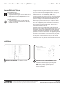
Installation
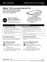
PREPARE EXISTING FIXTURE FOR INSTALLATION:
Remove all electrical parts and ballast compartment
cover leaving only the supply and gr ounding leads.
NOTE: Please properly dispose of lamps and
removed components.
2
PRIOR TO INSTALLATION: Turn o power to xture.
1

LED.com
© 2023 Current Lighting Solutions, LLC. All rights reserved. Information and specifications subject to change
without notice. All values are design or typical values when measured under laboratory conditions.
Page 3 of 4
(Rev 05/22/23)
IND452-Lumination-RLB-Series-Gen-2-LED-Strip-Retrofit-Luminaire-Installation-Guide
RetTM Strip Fixture Retrot Series (RLB2 Series) Installation Guide
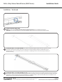
Installation - Continued
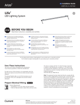
SECURE LED PANEL TO FIXTURE HOUSING: Once driver is properly energized, adjust bracket by opening or closing
to snugly t against xture housing and secure LED panel to xture housing by using the provided #8x1/2” self
drilling screws. If there are no brackets, then use the #8x1/2” self drilling screws to secure the LED panel directly to
the xture housing.
SECURE LED PANEL TO FIXTURE HOUSING (8ft. Kits): Connect the driver LED panel to the support LED panel using the 2 halves of
the connector. Once driver is properly energized, adjust bracket by opening or closing to snugly t against xture housing and secure
LED panels to xture housing by using the provided #8x1/2” self drilling screws. If there are no brackets, then use the #8x1/2” self
drilling screws to secure the LED panels directly to the xture housing.
4
5
CONNECT DRIVER TO MAIN FEED
NOTE: For sensor SKUs, Please ensure the sensor is properly secured prior to installing the LED panel.
CAUTION: For sensor SKUs, Please be careful with handling. Keep hand far from sensor location while installing.
3

LED.com
© 2023 Current Lighting Solutions, LLC. All rights reserved. Information and specifications subject to change
without notice. All values are design or typical values when measured under laboratory conditions.
Page 4 of 4
(Rev 05/22/23)
IND452-Lumination-RLB-Series-Gen-2-LED-Strip-Retrofit-Luminaire-Installation-Guide
RetTM Strip Fixture Retrot Series (RLB2 Series) Installation Guide
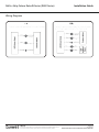
Wiring Diagrams
-
 1
1
-
 2
2
-
 3
3
-
 4
4


Lumination RLB Series Gen 2 LED Strip Retrofit Luminaire Guide d'installation
- Taper
- Guide d'installation
dans d''autres langues
Documents connexes
-
Lumination FM Series LED 12-Inch Flush Mount Ceiling Fixture Guide d'installation
-
-
-
-
-
-
-
-
-
Autres documents
-
GE current RefitTM Strip Fixture Retrofit Series Guide d'installation
-
Tetra Contour Gen 2 Side-Bend Guide d'installation
-
GE current RUL-Series Guide d'installation
-
-
-
-
EnviroLite EV407947WH50 Mode d'emploi
-
 Albeo AH2 Series Hazardous Locations Heavy Industrial High Bay Retrofit Kit Guide d'installation
-
 ARIZE Life² Guide d'installation

