Suncourt 8682668 Le manuel du propriétaire
- Catégorie
- Ventilateurs ménagers
- Taper
- Le manuel du propriétaire

INSTALLATION INSTRUCTIONS FOR IN-LINE DUCT FANS™
READ AND SAVE THESE INSTRUCTIONS
GENERAL SAFETY INSTRUCTIONS
WARNING – RISK OF ELECTRIC SHOCK. CAN CAUSE INJURY OR DEATH: DISCONNECT AND/OR LOCKOUT ALL REMOTE ELECTRIC POWER SUPPLIES BEFORE
SERVICING OR INSTALLING. WHEN THE SERVICE DISCONNECTING MEANS CANNNOT BE LOCKED, SECURELY FASTEN A PROMINENT WARNING DEVICE,
SUCH AS A TAG TO THE SERVICE PANEL.
WARNING – USE COPPER SUPPLY WIRES ONLY.
WARNING – FOR GENERAL VENTILATING USE ONLY. DO NOT USE TO EXHAUST HAZARDOUS OR EXPLOSIVE MATERIALS AND VAPORS. DO NOT USE TO
EXHAUST AIR LADEN WITH LINT, GREASE, OR OIL.
WARNING – PRODUCT INTENDED INSTALLATION IS AN INLINE DUCT FAN WITH BOTH ENDS CONNECTED TO DUCTWORK (SEE INSTALLATION INSTRUCTIONS
SECTION). FOR ANY OTHER INSTALLATION, GUARDS MUST BE INSTALLED TO PREVENT UNINTENTIONAL CONTACT WITH MOVING FAN BLADE UNLESS THE
UNIT IS MOUNTED WITH THE LOWEST MOVING PARTS AT LEAST 2.4M (8FT) ABOVE FLOOR OR GRADE LEVEL.
WARNING – FAN IS SUITABLE FOR ONLY CONNECTION TO A DUCT SUPPLYING SINGLE-ROOM DISCHARGE (MODELS: DB100C, DB200C, DB204C, DB205C,
DB206C, DB208C, DB306E, DB308E)
Use this unit only in the manner intended by the manufacturer. If you have any questions, contact the manufacturer. You may phone the manufacturer during normal business
hours at 1-800-999-3267 or submit your questions from our website: www.suncourt.com.
In-Line Duct FansTM are designed to boost dry conditioned (heated or cooled) indoor airflow in ducts of forced air systems with temperatures between 40°F (4°C) and 140°F
(60°C). Suncourt accepts no responsibility for use of this product in other applications.
EXPOSURE TO AIRFLOW TEMPERATURES EXCEEDING 140°F (60°C) WILL PERMANENTLY DAMAGE THE FAN AND VOID THE WARRANTY.
ELECTRICAL SAFETY INSTRUCTIONS
WARNING – To Reduce the Risk Of Fire, Electrical Shock, or Injury to Persons, Observe the Following:
Installation work and electrical wiring must be done by a qualified person(s) in accordance with all applicable codes and standards, including fire-rated construction and
accessibility.
Your In-Line Duct FanTM must be connected to a 110/120 Volt AC, 60Hz fuse or circuit breaker protected power source only in a manner approved by all applicable codes. Never
connect your In-Line Duct FanTM to a 240 Volt AC blower motor or other 240 Volt AC system. Never connect your In-Line Duct FanTM to a variable-speed (ECM) furnace blower.
For a two-speed In-Line Duct FanTM, never connect directly to multiple taps on the furnace blower; always use isolation relays.
The power source must be protected by a fuse or circuit breaker rated at a minimum of 15 amperes.
You may also supply power to your In-Line Duct FanTM using the Suncourt DuctStat® Temperature Sensitive SwitchTM or a standard on/off switch (Purchased Separately).
For In-Line Duct FansTM without power cord attached, all connections to the power supply must be made inside the electrical box provided with the unit. Use power supply
conductors and wire nuts of appropriate size and type. Attach a wire nut to any unused lead in a 2-speed In-Line Duct FanTM. The power supply wiring must always include a
ground wire properly terminated at the fan (green wire).
For In-Line Duct FansTM with power cord attached, the cord can be plugged in to any standard (NEMA 5-15) 3-prong outlet. The outlet supplying power to the cord must include a
ground terminal properly connected to a ground source. The power cord should be secured to a location where it is not subject to damage, abrasion, or temperatures exceeding
140°F (60°C).
For maximum performance and minimum noise, the best location to install your In-Line Duct FanTM is 6–10 feet from the register that needs the boosted air.
To prevent air leaks, use a good quality aluminum foil duct tape to seal the seams in the ductwork after installing the In-Line Duct FanTM.
By utilizing tapered reducers, you may install larger diameter duct fans in smaller diameter ducts to achieve greater boosted airflow.
Always leave your In-Line Duct FanTM accessible for maintenance, cleaning, or repair.
ACCESSORY INFO
Ductstat® Temperature Sensitive SwitchTM, model DS100
The In-Line Duct FanTM can be controlled by our Ductstat® to operate the fan. This is the easiest way to interlock your In-Line Duct FanTM to your furnace. Simply plug your fan
into the Ductstat® and set the controls to operate the fan only when conditioned air is sensed inside the boosted duct. Please visit www.suncourt.com for more info on the
Ductstat® Temperature Sensitive SwitchTM.
Standard Variable Speed Control, model VS100
The speed of your non-corded In-Line Duct FanTM (models DB412E, DB414E, DB416E) can be controlled with our model VS100 Variable Speed Control. This speed control
utilizes solid-state circuitry to safely adjust the fan speed without damaging the motor. The speed control mounts inside a standard 2x4 electrical box and includes a cover plate
and mounting hardware.
GENERAL INSTALLATION NOTES
WARNING – NEVER USE A RHEOSTAT OR LIGHT DIMMER SWITCH TO CONROL YOUR FAN SPEED. A SOLID-STATE SPEED CONTROLLER MUST
BE USED TO AVOID DAMAGE TO THE MOTOR.
Please visit www.suncourt.com for more info on these or other accessories.
In-Line Duct FansTM with power cord attached have the model number extension DBxxxC
In-Line Duct FansTM with electrical box attached have the model number extension DBxxxE
INSTALLATION INSTRUCTIONS
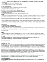
1. Locate the place in the duct where you wish to install the In-Line Duct Fan™.
2. Tape the enclosed template to the duct with the arrow pointing in the direction of the airflow. Cut out the required opening by first drilling a pilot hole and cutting
along the dashed line using a jig saw or tin snips.
3. Place the Inductor® In-Line Duct Fan™ in the opening, making sure that the fan blade can turn freely. Align the arrow on the unit in the direction of airflow.
4a. Connect the spring through the middle hole provided in the base plate, stretch the spring over the duct and through the middle hole on the other side of the
loose plate. Bend the ends of the spring over to secure, providing a snug installation.
4b. Secure the In-Line Duct Fan™ in position with the supplied #6 sheet metal screws using the provided holes in the base plate of the unit.
5. Finish the installation by covering the seams in the duct with a good quality aluminum foil duct tape.
MODEL: DB100C
MODELS: DB200C, DB204C
1. Locate the place in the duct where you wish to install the In-Line Duct Fan™. Align arrow label on unit in direction of airflow.
FLEXIBLE DUCT
2a. Simply cut the flexible duct and slide the In-Line Duct Fan™ in place by slipping the cut flexible duct ends over the crimped ends
on the In-Line Duct Fan™, making sure the unit is well supported.
Complete the installation by securing the In-Line Duct Fan™ to the flexible duct with a good quality aluminum foil duct tape or nylon
cable ties.
METAL DUCT
2b. Remove a section of the existing ductwork and slide the In-Line Duct Fan™ in place by slipping the duct ends over the crimped
ends of the unit. Complete the installation by securing the In-Line Duct Fan™ to the metal duct with the supplied #6 sheet metal
screws spaced evenly around the circumference on each end of the unit.
3. Finish the installation by covering the seams in the duct with a good quality aluminum foil duct tape.
1. Locate the place in the duct where you wish to install the In-Line Duct Fan™. Align arrow label on unit in the direction of the airflow.
FLEXIBLE DUCT
2a. Install connectors onto any uncrimped ends of the unit. Then simply cut the flexible duct and slide the In-Line Duct Fan™ in place
by slipping the cut flexible duct ends over the connectors or crimped ends on the In-Line Duct Fan™, making sure the unit is well
supported. Complete the installation by securing the In-Line Duct Fan™ to the flexible duct with a good quality aluminum foil duct tape
or nylon cable ties.
METAL DUCT
2b. Install connectors onto any uncrimped ends of the unit, or crimp your existing ductwork. Then simply place the existing duct over
the crimped ends of the unit, or the existing crimped ductwork into the unit. Secure the In-Line Duct Fan™ to the metal duct with the
supplied #6 sheet metal screws spaced evenly around the circumference on each end of the unit.
3. Finish the installation by covering the seams in the duct with a good quality aluminum foil duct tape.
MODELS: DB205C, 206C, 208C, 210C, 212C, 306E, 308E, 310E, 412E, 414E, 416E, 6GTC
WIRING INSTRUCTIONS FOR IN-LINE DUCT FANS™ WITHOUT POWER CORDS ATTACHED:
DB306E, DB308E and DB310E:
Never connect red and black wires together!
IMPORTANT NOTICE - In-Line Dut FansTM without power cord attached.
Single Speed - DB4xxE
The motor of your In-Line Duct Fan™ may have 1 White and 1 Black wire or 2 Black wires. If you have a motor with a White and Black wire, connect the White motor wire to
the White supply wire and the Black motor wire to the Black supply wire. If you have a motor with 2 black wires, connect either of the Black wires to the White supply wire and
the other Black wire to the Black supply wire.
Two Speed - DB3xxE
Make sure you connect the colored wire as shown in the table below. Failure to connect correctly will destroy the motor. Make sure to attach a wire nut to any unused wire
lead. No warranty claim for an incorrectly wired motor will be accepted by Suncourt.
Airflow
Existing
flexible duct
Secure with duct tape or
nylon cable ties
Airflow
Secure with
sheet metal screws
Existing
metal duct
DB306E, DB308E, and DB310E: Never connect LOW and HIGH wires together. For single
speed operation, select the LOW or HIGH speed wire for your application and attach a
wire nut to the unused wire lead. When either the LOW or HIGH speed wire is energized
there will be voltage present in the other wire.
For two-speed operation you must never supply power to both LOW and HIGH speed leads
simultaneously. You must isolate the power to LOW and HIGH speeds using a relay or
switch. If connecting to a HVAC blower please consult with the system manufacturer or
qualified HVAC contractor. Never connect to a DC blower system.
Green wire from
Suncourt
motor.
Green wire from
Suncourt
motor.
DB412E
DB414E DB416E
Black wire or White wire
(see note above) from
Suncourt motor.
White (neutral or common)
wire from power source Black (hot or line)
from power source
Green (ground) wire
from power source
Black wire from
Suncourt
motor.
MODELS
DB306E, DB308E,
DB310E
White wire from
Suncourt
motor.
LOW fan speed: Red
wire from
Suncourt
motor.
HIGH fan speed: Black
wire from
Suncourt
motor.
Suncourt Inc. recommends that you clean your In-Line Duct Fan™ at regular intervals, similar to what is recommended for the fan of your furnace, no less than twice a year.
Keep your In-Line Duct Fan™ free of lint, dust, and debris. The In-Line Duct Fan™ must never be exposed to temperatures over 140°F (60°C).
CLEANING AND MAINTENANCE
ONE YEAR LIMITED WARRANTY
Subject to the following limitations, Suncourt Inc. (manufacturer) warrants that the In-Line Duct Fan™ will, for 1 (one) year from date of original retail purchase, but not
exceeding 2 (two) years from date of manufacture, remain free from appearance of defects in workmanship or materials.
This warranty is subject to the following limitations: (a) manufacturer’s liability is limited to the replacement or repair of the unit, as decided by the manufacturer; (b) a defective
unit must be returned, prepaid, with proof of purchase, well packaged to avoid damage in transit; and (c) this warranty does not apply to defects resulting from the alteration,
abuse, accidental damage, unauthorized repair, or misuse of the unit. This warranty is given in lieu of all other warranties, guarantees, and conditions on manufacturer’s part,
and the manufacturer shall have no tortious or other liability in respect to this In-Line Duct Fan™. Ship unit to Suncourt Inc. only after obtaining a Return Goods Authorization
(RGA) number. Returns without this RGA number will not be accepted.
Actual product appearance may differ from illustrations. Suncourt reserves the right to modify any or all of its products' features, designs, components and specifications
without notice.
Airflow
Secure with
sheet metal screws
Existing
metal duct
Airflow
Existing
flexible duct
Secure with duct tape or
nylon cable ties
CONSIGNES GÉNÉRALES DE SÉCURITÉ
LIRE ET CONSERVER CES DIRECTIVES
DIRECTIVES POUR L’INSTALLATION DE VENTILATEURS IN-LINE DUCT FANS™
AVERTISSEMENT - RISQUE DE CHOC ÉLECTRIQUE. PEUT PROVOQUER DES BLESSURES OU LA MORT: DÉCONNECTEZ ET / OU VERROU TOUS ÉLECTRIQUE À
DISTANCE ALIMENTATIONS AVANT DE RÉPARER OU INSTALLATION. QUAND LES MOYENS
DÉBRANCHANT DE SERVICE NE PEUVENT PAS ÊTRE VERROUILLES, ATTACHEZ SOLIDEMENT UN PROÉMINENT DISPOSITIF D'AVERTISSEMENT, TEL QU'UNE
ETIQUETTE AU PANNEAU DE SERVICE.
AVERTISSEMENT - EMPLOI FIL DE CUIVRE SEULEMENT.
ADVERTISSEMENT - POUR GÉNÉRAL AÉRATION SEULEMENT. N'UTILISEZ PAS POUR ÉPUISER MATÉRIAUX DANGEREUX OU EXPLOSIFS ET VAPEURS.
N'UTILISEZ PAS À D'ÉCHAPPEMENT D'AIR CONTENANT LINT, DE LA GRAISSE OU DE L'HUILE.
AVERTISSEMENT - INTENTIONNÉ PRODUIT INSTALLATION EST POUR INLINE CONDUIT FAN AVEC LES DEUX EXTRÉMITÉS
RACCORDÉS À CONDUIT (VOIR NOTICE D'INSTALLATION SECTION). POUR TOUTE AUTRE INSTALLATION, DES PROTECTEURS DOIVENT ÊTRE INSTALLÉS POUR
EMPÊCHER TOUT CONTACT INVOLONTAIRE AVEC LE DÉPLACEMENT FAN BLADE EXCEPTÉ SI L'UNITÉ EST MONTÉ AVEC LE PLUS BAS PIÈCES AU MOINS 2.4 M
(8FT) AU-DESSUS PLANCHER OU TERRE NIVEAU.
AVERTISSEMENT - FAN EST SEULEMENT CONVENABLE POUR CONNEXION À UN CONDUIT ALIMENTATION AVEC CHAMBRE SIMPLE DÉCHARGE
(MODÈLES: DB100C, DB200C, DB204C, DB205C, DB206C, DB208C, DB306E, DB308E)
Utilisez cet appareil uniquement de la manière prévue par le fabricant. Si vous avez des questions, contactez le fabricant.
Vous pouvez téléphoner au fabricant pendant les heures normales de bureau au 1-800-999-3267 ou soumettre vos questions sur notre site web: www.suncourt.com.
In-Line Duct FansTM sont conçus pour augmenter sèche climatise (chauffé ou refroidi) intérieur débit d'air dans les conduits forceé de systèmes à air avec des températures entre
40° F (4° C) et 140° F (60° C). Suncourt accepte aucune responsabilité pour l'utilisation de ce produit dans d'autres applications.
EXPOSITION À DES TEMPÉRATURES DE DÉBIT D'AIR SUPÉRIEURE À 140° F (60° C) ENDOMMAGER EN PERMANENCE LE FAN ET ANNULER LA GARANTIE.
CONSIGNES DE SÉCURITÉ ÉLECTRIQUE
AVERTISSEMENT - Pour ramener le risque du feu ou de choc électrique ou de dommages aux personnes, observez ce qui suit:
Le travail d'installation et le câblage électrique doivent étre faits par la personne qualifiée(s) selon tous les codes et normes applicables, y compris la construction feu-évaluée.
Votre ventilateur In-Line Duct FanTM doit être branché sur une alimentation à courant alternatif de 110/120 volts, 60Hz protégée par une fusible ou un disjoncteur seulement
d'une maniére approuvée par tous les codes en vigueur. Ne jamais brancher votre In-Line Duct FanTM à un moteur de soufflante avec courant alternatif de 240 volts ou à
d'autres systèmes fonctionnant sur 240 volts. Ne jamais brancher votre In-Line Duct FanTM à une vitesse variable (ECM) de soufflante de chauffage. Pour un deux-vitesse
In-Line Duct FanTM, ne jamais brancher directement sur plusieurs robinets sur le four de soufflante; utilisez toujours l'isolement relais.
La source d'énergie doit être protégée par un fusible ou un disjoncteur évalué à 15 ampères au minimum.
Vous pouvez également puissance votre In-Line Duct FanTM utilisant le Suncourt DuctStat® Temperature Sensitive SwitchTM ou une norme interrupteur marche / arrêt
(vendu séparément).
Pour In-Line Duct FansTM sans cordon d'alimentation fixé, toutes les connexions à l'alimentation doivent être faites à l'intérieur de la boîte électrique fourni avec l'appareil.
Utilisez conducteurs d'alimentation et des écrous de fil de approprié taille et type. Fixer un écrou de fil à n'importe quel plomb inutilisé dans un 2 vitesses In-Line Duct FanTM.
Le câblage d'alimentation doit toujours comporter un fil de terre correctement terminé au le ventilateur (fil vert).
Pour In-Line Duct FansTM avec cordon d'alimentation fixé, le cordon peut être branché en n'importe quel standard (NEMA 5-15) de prise avec mise à la terre. La prise fournissé
alimenter à le cordon doit inclure une terminal de terre ce qui est correctement connecté à une sol source. Le cordon d'alimentation doit être fixé à un endroit où il ne est pas
soumis à des dégâts, à l'abrasion, ou à des températures dépassant 140° F (60° C).
NOTES D'INSTALLATION GÉNÉRALES
Pour performance maximale et un minimum de bruit, le meilleur endroit pour installer votre In-Line Duct FanTM est de 6 à 10 pieds par la grille d'aération qui besoins l'air d'être
augmenteé.
Pour éviter les fuites d'air, utiliser un bon aluminium de qualité conduit de ruban métallique pour sceller les joints dans les conduits après l'installation du In-Line Duct FanTM.
En utilisant réducteurs coniques, vous pouvez installer grands ventilateurs pour gaines de diamètre dans les conduits de diamètre plus petit pour atteindre une plus grande
augmenter de circulation de l'air.
Toujours laisser votre In-Line Duct FanTM accessibles pour l'entretien, le nettoyage, ou la réparation.
INFO ACCESSOIRE
Ductstat® Temperature Sensitive SwitchTM, modèles DS100
L'In-Line Duct FanTM peut être contrôlé par notre Ductstat® à faire fonctionner le ventilateur. Ce est la aisément façon de verrouiller votre In-Line Duct FanTM à votre fournaise. Il
suffit de brancher votre ventilateur à le Ductstat® et réglez les commandes à fonctionner le ventilateur seulement lorsque conditionné air est détecté à l'intérieur du conduit avec
augmenteé air. Plaît visitez www.suncourt.com pour plus d'infos sur le Ductstat® Temperature Sensitive SwitchTM
Norme de contrôle de vitesse variable, modèle VS100
La vitesse de votre non-filaires conduit In-Line Duct FanTM (modèles DB412E, DB414E, DB416E) peuvent être contrôlés avec modèle Suncourt VS100 Contrôle de vitesse
variable. Cette régulation de vitesse utilise solid state circuits en toute sécurité pour régler la vitesse du ventilateur sans endommager le moteur. Le contrôle de la vitesse
montures standard de l'intérieur 2x4 boîtier électrique et comprend une plaque de couvercle et la boulonnerie de montage.
AVERTISSEMENT - NE JAMAIS UTILISER UN RHÉOSTAT OU ATTÉNUATEUR POUR CONTRÔLER VOTRE VITESSE DE VENTILATEUR. UN ÉTAT SOLIDE
CONTRÔLEUR DE VITESSE DOIT ÊTRE UTILISÉ POUR ÉVITER D'ENDOMMAGER LE MOTEUR.
Veuillez visiter www.suncourt.com pour plus d'infos sur ces ou autres accessoires.
INSTALLATION INSTRUCTIÓNS
In-Line Duct FansTM avec la boîte électrique joint ayez suffixe DbxxxE
In-Line Duct FansTM avec le cordon attaché ayez suffix DBxxxC
Circulation
d’air
Bien attacher avec des vis á tôle
Conduit
métallique existant
CONDUIT FLEXIBLE
2a. Installez les raccords sur n'importe quelle des extrémités pas ondulées de l'appareil. Puis coupez simplement le conduit
flexible et placez le ventilateur In-Line Duct Fan™ en glissant les extrémités du conduit flexible coupé sur les raccords ou extrémités
ondulées sur le ventilateur In-Line Duct Fan™, en s'assurant que l'appareil est bien supporté. Terminez l'installation en attachant
bien le ventilateur In-Line Duct Fan™ au conduit flexible avec du ruban adhésif pour conduits ou des attache-câbles en nylon.
CONDUIT MÉTALLIQUE
2b. Installer les raccords sur n'importe quelle des extrémités pas ondulées de l'appareil, ou sertir vos conduits existants. Puis
placez simplement le conduit existant sur les extrémités ondulées de l'appareil, ou les conduits ondulés existants dans l'appareil.
Bien attacher le ventilateur In-Line Duct Fan™ au conduit métallique avec les vis à tôle No.6 fournies espacées à égale distance
autour de la circonférence sur chaque extrémité de l'appareil.
3. Couvrez les coutures dans le conduit avec ruban adhésif aluminium.
1. Trouvez l'endroit dans le conduit où vous voulez installer le ventilateur In-Line Duct Fan™. Aligner la flèche sur l'appareil dans la direction de circulation d'air.
MODÈLES: DB205C, 206C, 208C, 210C, 212C, 306E, 308E, 310E, 412E, 414E, 416E, 6GTC
NOTIFICATION IMPORTANTE - In-Line Dut FansTM sans cordon d'alimentation est branché.
Vitesse Simple - DB4xxE
Le moteur de votre In-Line Duct Fan™ peut avoir 1 fil Blanc et 1 Noir ou 2 fils Noirs. Si vous avez un moteur avec un fil Blanc et Noir, reliez le fil Blanc de moteur au fil Blanc
d'approvisionnement et le fil Noir de moteur au fil Noir d'approvisionnement. Si vous avez un moteur avec 2 fils Noirs, reliez l'un ou l'autre des fils Noirs au fil Blanc
d'approvisionnement et à l'autre fil Noir au fil Noir d'approvisionnement.
À Deux Vitesses -DB3xxE
Veillez-vous pour relier le fil coloré comme montré ci-dessous. Le manque de se relier correctement détruira le moteur. Assurez-vous d'attacher un serre-fils à n'importe quel fil
inutilisé. Aucune réclamation de garantie pour un moteur inexactement de câble ne sera acceptée par Suncourt.
Circulation
d’air
Conduit flexible
existant Fixez avec du ruban adhésif pour
conduits de bonne qualité ou des
attache-câbles en nylon
Circulation
d’air
Bien attacher avec des vis á tôle
Conduit
métallique existant
DB306E, DB308E et DB310E: Ne reliez ensemble jamais les fils LENTE
et RAPIDE. Pour un fonctionnement à vitesse seul, sélectionnez la
vitesse de fils LENTE ou RAPIDE pour votre application et attacher un
serre-fils quel fil inutilisé. Lorsque le fils de vitesse LENTE ou RAPIDE
est alimenté sous tension l'autre fil aura lieu. Pour fonctionnement de
deux vitesses ne reliez approvisionner jamais alimenter les deux vitesse
de fils LENTE et RAPIDE simultanément. Vous moût isoler le alimentation
de vitesses LENTE et RAPIDE à l'aide d'un relais ou un commutator
électrique.
Si la connexion à un ventilateur de CVC veuillez consulter le fabricant du
système ou un installateur HVAC. Ne jamais raccorder à un système de
ventilateur DC.
Instructions de câblage pour In-Line Duct Fans™ sans les cordons de secteur ont attaché:
DB306E: Ne reliez ensemble jamais les fils jaunes et rouges!
DB308E et DB310E: Ne reliez ensemble jamais les fils rouges et noirs!
Suncourt Inc. recommande que vous nettoyez votre ventilateur In-Line Duct Fan™ à des intervalles réguliers, semblable à ce qui est recommandé pour le ventilateur de votre
chaudière, mais au moins deux fois par an. Garder votre ventilateur In-Line Duct Fan™ propre sans peluches, sans poussière ni débris. Le ventilateur In-Line Duct Fan™ ne
doit jamais être exposé à des températures au-dessus de 60°C (140°F).
GARANTIE D’UN AN
NETTOYAGE ET ENTRETIEN
Sous réserve des limitations suivantes, Suncourt Inc. (le fabricant) garantie le ventilateur In-Line Duct Fan™ contre tout défaut de pièce et de main d'oeuvre pour une période
d'un (1) an à partir de la date d'achat original, mais n'excédant pas deux ans à partir de la date de fabrication. Cette garantie est sous réserve des limitations suivantes: (a) la
responsabilité du fabricant est limitée au remplacement ou à la réparation de l'appareil, suivant la décision par le fabricant; (b) un appareil défectueux doit être renvoyé, bien
emballé pour éviter des dommages en transit, les frais de transport payés à l'avance et avec preuve d'achat; et (c) cette garantie ne s'applique pas aux dommages causés par
des modifications, l'abus, des dommages accidentels, des réparations pas autorisées, ou la mauvaise utilisation de l'appareil. Cette garantie est donnée à la place de toutes
autres garanties et conditions de la part du fabricant, et le fabricant n'aura aucune autre responsabilité en ce qui concerne ce ventilateur In-Line Duct Fan™. Expédiez l'unité à
Suncourt Inc seulement après l'obtention d'une autorisation de retour de marchandise (RGA). Les retours sans ce numéro de RGA ne seront pas acceptées. L’apperance de
produit peut différer des illustrations. Suncourt se réserve le droit de modifier partiellement ou entierement les caractéristiques du produit, de conceptions, de composants et de
caractéristiques sans préavis.
Vert câblage du
Suncourt moteur.
Vert câblage du
Suncourt moteur.
Vert câblage du
Suncourt moteur.
DB412E
DB414E DB416E
Noir ou blanc câblage
du moteur. Le Suncourt
moteur n‘est pas polarise.
Blanc (neutre ou commun)
câblage de la source
d‘alimentation.
Noir (tension/conductrice de
courant) câblage de la source
d ‘ alimentation.
Vert (Terre/Masse) câblage
de la source d ‘ alimentation.
Noir câblage du moteur.
Remarques: Le Suncourt
moteur n‘est pas polarise.
DB306E
MODÈLES
Noir câblage du
Suncourt moteur.
Vitesse Lente: Jaune câblage
du Suncourt moteur.
Vitesse Rapide: Rouge câblage
du Suncourt moteur.
DB308E, DB310E
Blanc câblage du
Suncourt moteur.
Vitesse Lente: Rouge câblage
du Suncourt moteur.
Vitesse Rapide: Noir câblage
du Suncourt moteur.
Corded-WNT600-0815-A01-PA
MODÈLES: DB100C
1. Trouvez l'endroit dans le conduit où vous voulez installer le ventilateur In-Line Duct Fan™.
2. Collez le gabarit ci-joint au conduit avec la flèche orientée dans la direction du courant d'air. Découpez l'ouverture requise en perçant premièrement un trou
pilote et en coupant le long des lignes pointillées avec une scie sauteuse ou des cisailles.
3. Placez le ventilateur Inductor® In-Line Duct Fan™ dans l'ouverture, en s'assurant que l'hélice du ventilateur puisse tourner librement. Alignez la flèche sur
l'appareil dans la direction de circulation d'air.
4a. Accrochez le ressort à travers le trou du milieu prévu dans la plaque de base, tirez sur le ressort et replier l'extrémité pour obtenir une installation bien ajustée.
4b. Bien serrer en place le ventilateur In-Line Duct Fan™ avec les vis à tôle No. 6 fournies en utilisant les trous prévus dans la plaque de base de l'appareil. Vous
pouvez terminer l'installation en recouvrant les joints dans le conduit avec du ruban adhésif pour conduits de bonne qualité.
5. Couvrez les coutures dans le conduit avec ruban adhésif aluminium.
CONDUIT FLEXIBLE
2a. Coupez simplement le conduit flexible et placez le ventilateur In-Line Duct Fan™ en glissant les extrémités du conduit flexible
coupé sur les extrémités ondulées sur le ventilateur In-Line Duct Fan™, en s'assurant que l'appareil soit bien supporté. Terminez
l'installation en attachant bien le ventilateur In-Line Duct Fan™ au conduit flexible avec du ruban adhésif pour conduits de bonne
qualité ou des attache-câbles en nylon.
CONDUIT MÉTALLIQUE
2b. Enlevez une partie des conduits existants et placez le ventilateur In-Line Duct Fan™ en glissant les extrémités du conduit sur les
extrémités ondulées de l'appareil. Terminez l'installation en attachant bien le ventilateur In-Line Duct Fan™ au conduit métallique
avec les vis à tôle No.6 fournies espacées à égale distance autour de la circonférence sur chaque extrémité de l'appareil.
3. Couvrez les coutures dans le conduit avec ruban adhésif aluminium.
1. Trouvez l'endroit dans le conduit où vous voulez installer le ventilateur In-Line Duct Fan™. Aligner la flèche sur l'appareil dans la direction de circulation d'air.
MODÈLES: DB200C, DB204C
Circulation
d’air
Conduit flexible
existant Fixez avec du ruban adhésif pour
conduits de bonne qualité ou des
attache-câbles en nylon
SUNCOURT INC.
500 W. SECOND AVENUE • P.O. BOX 40
DURANT, IOWA 52747-0040
1-800-999-FANS (3267)
www.suncourt.com
Corded-WNT600-0815-A01-PA
SUNCOURT INC.
500 W. SECOND AVENUE • P.O. BOX 40
DURANT, IOWA 52747-0040
1-800-999-FANS (3267)
www.suncourt.com

INSTALLATION INSTRUCTIONS FOR IN-LINE DUCT FANS™
READ AND SAVE THESE INSTRUCTIONS
GENERAL SAFETY INSTRUCTIONS
WARNING – RISK OF ELECTRIC SHOCK. CAN CAUSE INJURY OR DEATH: DISCONNECT AND/OR LOCKOUT ALL REMOTE ELECTRIC POWER SUPPLIES BEFORE
SERVICING OR INSTALLING. WHEN THE SERVICE DISCONNECTING MEANS CANNNOT BE LOCKED, SECURELY FASTEN A PROMINENT WARNING DEVICE,
SUCH AS A TAG TO THE SERVICE PANEL.
WARNING – USE COPPER SUPPLY WIRES ONLY.
WARNING – FOR GENERAL VENTILATING USE ONLY. DO NOT USE TO EXHAUST HAZARDOUS OR EXPLOSIVE MATERIALS AND VAPORS. DO NOT USE TO
EXHAUST AIR LADEN WITH LINT, GREASE, OR OIL.
WARNING – PRODUCT INTENDED INSTALLATION IS AN INLINE DUCT FAN WITH BOTH ENDS CONNECTED TO DUCTWORK (SEE INSTALLATION INSTRUCTIONS
SECTION). FOR ANY OTHER INSTALLATION, GUARDS MUST BE INSTALLED TO PREVENT UNINTENTIONAL CONTACT WITH MOVING FAN BLADE UNLESS THE
UNIT IS MOUNTED WITH THE LOWEST MOVING PARTS AT LEAST 2.4M (8FT) ABOVE FLOOR OR GRADE LEVEL.
WARNING – FAN IS SUITABLE FOR ONLY CONNECTION TO A DUCT SUPPLYING SINGLE-ROOM DISCHARGE (MODELS: DB100C, DB200C, DB204C, DB205C,
DB206C, DB208C, DB306E, DB308E)
Use this unit only in the manner intended by the manufacturer. If you have any questions, contact the manufacturer. You may phone the manufacturer during normal business
hours at 1-800-999-3267 or submit your questions from our website: www.suncourt.com.
In-Line Duct FansTM are designed to boost dry conditioned (heated or cooled) indoor airflow in ducts of forced air systems with temperatures between 40°F (4°C) and 140°F
(60°C). Suncourt accepts no responsibility for use of this product in other applications.
EXPOSURE TO AIRFLOW TEMPERATURES EXCEEDING 140°F (60°C) WILL PERMANENTLY DAMAGE THE FAN AND VOID THE WARRANTY.
ELECTRICAL SAFETY INSTRUCTIONS
WARNING – To Reduce the Risk Of Fire, Electrical Shock, or Injury to Persons, Observe the Following:
Installation work and electrical wiring must be done by a qualified person(s) in accordance with all applicable codes and standards, including fire-rated construction and
accessibility.
Your In-Line Duct FanTM must be connected to a 110/120 Volt AC, 60Hz fuse or circuit breaker protected power source only in a manner approved by all applicable codes. Never
connect your In-Line Duct FanTM to a 240 Volt AC blower motor or other 240 Volt AC system. Never connect your In-Line Duct FanTM to a variable-speed (ECM) furnace blower.
For a two-speed In-Line Duct FanTM, never connect directly to multiple taps on the furnace blower; always use isolation relays.
The power source must be protected by a fuse or circuit breaker rated at a minimum of 15 amperes.
You may also supply power to your In-Line Duct FanTM using the Suncourt DuctStat® Temperature Sensitive SwitchTM or a standard on/off switch (Purchased Separately).
For In-Line Duct FansTM without power cord attached, all connections to the power supply must be made inside the electrical box provided with the unit. Use power supply
conductors and wire nuts of appropriate size and type. Attach a wire nut to any unused lead in a 2-speed In-Line Duct FanTM. The power supply wiring must always include a
ground wire properly terminated at the fan (green wire).
For In-Line Duct FansTM with power cord attached, the cord can be plugged in to any standard (NEMA 5-15) 3-prong outlet. The outlet supplying power to the cord must include a
ground terminal properly connected to a ground source. The power cord should be secured to a location where it is not subject to damage, abrasion, or temperatures exceeding
140°F (60°C).
For maximum performance and minimum noise, the best location to install your In-Line Duct FanTM is 6–10 feet from the register that needs the boosted air.
To prevent air leaks, use a good quality aluminum foil duct tape to seal the seams in the ductwork after installing the In-Line Duct FanTM.
By utilizing tapered reducers, you may install larger diameter duct fans in smaller diameter ducts to achieve greater boosted airflow.
Always leave your In-Line Duct FanTM accessible for maintenance, cleaning, or repair.
ACCESSORY INFO
Ductstat® Temperature Sensitive SwitchTM, model DS100
The In-Line Duct FanTM can be controlled by our Ductstat® to operate the fan. This is the easiest way to interlock your In-Line Duct FanTM to your furnace. Simply plug your fan
into the Ductstat® and set the controls to operate the fan only when conditioned air is sensed inside the boosted duct. Please visit www.suncourt.com for more info on the
Ductstat® Temperature Sensitive SwitchTM.
Standard Variable Speed Control, model VS100
The speed of your non-corded In-Line Duct FanTM (models DB412E, DB414E, DB416E) can be controlled with our model VS100 Variable Speed Control. This speed control
utilizes solid-state circuitry to safely adjust the fan speed without damaging the motor. The speed control mounts inside a standard 2x4 electrical box and includes a cover plate
and mounting hardware.
GENERAL INSTALLATION NOTES
WARNING – NEVER USE A RHEOSTAT OR LIGHT DIMMER SWITCH TO CONROL YOUR FAN SPEED. A SOLID-STATE SPEED CONTROLLER MUST
BE USED TO AVOID DAMAGE TO THE MOTOR.
Please visit www.suncourt.com for more info on these or other accessories.
In-Line Duct FansTM with power cord attached have the model number extension DBxxxC
In-Line Duct FansTM with electrical box attached have the model number extension DBxxxE
INSTALLATION INSTRUCTIONS
1. Locate the place in the duct where you wish to install the In-Line Duct Fan™.
2. Tape the enclosed template to the duct with the arrow pointing in the direction of the airflow. Cut out the required opening by first drilling a pilot hole and cutting
along the dashed line using a jig saw or tin snips.
3. Place the Inductor® In-Line Duct Fan™ in the opening, making sure that the fan blade can turn freely. Align the arrow on the unit in the direction of airflow.
4a. Connect the spring through the middle hole provided in the base plate, stretch the spring over the duct and through the middle hole on the other side of the
loose plate. Bend the ends of the spring over to secure, providing a snug installation.
4b. Secure the In-Line Duct Fan™ in position with the supplied #6 sheet metal screws using the provided holes in the base plate of the unit.
5. Finish the installation by covering the seams in the duct with a good quality aluminum foil duct tape.
MODEL: DB100C
MODELS: DB200C, DB204C
1. Locate the place in the duct where you wish to install the In-Line Duct Fan™. Align arrow label on unit in direction of airflow.
FLEXIBLE DUCT
2a. Simply cut the flexible duct and slide the In-Line Duct Fan™ in place by slipping the cut flexible duct ends over the crimped ends
on the In-Line Duct Fan™, making sure the unit is well supported.
Complete the installation by securing the In-Line Duct Fan™ to the flexible duct with a good quality aluminum foil duct tape or nylon
cable ties.
METAL DUCT
2b. Remove a section of the existing ductwork and slide the In-Line Duct Fan™ in place by slipping the duct ends over the crimped
ends of the unit. Complete the installation by securing the In-Line Duct Fan™ to the metal duct with the supplied #6 sheet metal
screws spaced evenly around the circumference on each end of the unit.
3. Finish the installation by covering the seams in the duct with a good quality aluminum foil duct tape.
1. Locate the place in the duct where you wish to install the In-Line Duct Fan™. Align arrow label on unit in the direction of the airflow.
FLEXIBLE DUCT
2a. Install connectors onto any uncrimped ends of the unit. Then simply cut the flexible duct and slide the In-Line Duct Fan™ in place
by slipping the cut flexible duct ends over the connectors or crimped ends on the In-Line Duct Fan™, making sure the unit is well
supported. Complete the installation by securing the In-Line Duct Fan™ to the flexible duct with a good quality aluminum foil duct tape
or nylon cable ties.
METAL DUCT
2b. Install connectors onto any uncrimped ends of the unit, or crimp your existing ductwork. Then simply place the existing duct over
the crimped ends of the unit, or the existing crimped ductwork into the unit. Secure the In-Line Duct Fan™ to the metal duct with the
supplied #6 sheet metal screws spaced evenly around the circumference on each end of the unit.
3. Finish the installation by covering the seams in the duct with a good quality aluminum foil duct tape.
MODELS: DB205C, 206C, 208C, 210C, 212C, 306E, 308E, 310E, 412E, 414E, 416E, 6GTC
WIRING INSTRUCTIONS FOR IN-LINE DUCT FANS™ WITHOUT POWER CORDS ATTACHED:
DB306E, DB308E and DB310E:
Never connect red and black wires together!
IMPORTANT NOTICE - In-Line Dut FansTM without power cord attached.
Single Speed - DB4xxE
The motor of your In-Line Duct Fan™ may have 1 White and 1 Black wire or 2 Black wires. If you have a motor with a White and Black wire, connect the White motor wire to
the White supply wire and the Black motor wire to the Black supply wire. If you have a motor with 2 black wires, connect either of the Black wires to the White supply wire and
the other Black wire to the Black supply wire.
Two Speed - DB3xxE
Make sure you connect the colored wire as shown in the table below. Failure to connect correctly will destroy the motor. Make sure to attach a wire nut to any unused wire
lead. No warranty claim for an incorrectly wired motor will be accepted by Suncourt.
Airflow
Existing
flexible duct
Secure with duct tape or
nylon cable ties
Airflow
Secure with
sheet metal screws
Existing
metal duct
DB306E, DB308E, and DB310E: Never connect LOW and HIGH wires together. For single
speed operation, select the LOW or HIGH speed wire for your application and attach a
wire nut to the unused wire lead. When either the LOW or HIGH speed wire is energized
there will be voltage present in the other wire.
For two-speed operation you must never supply power to both LOW and HIGH speed leads
simultaneously. You must isolate the power to LOW and HIGH speeds using a relay or
switch. If connecting to a HVAC blower please consult with the system manufacturer or
qualified HVAC contractor. Never connect to a DC blower system.
Green wire from
Suncourt
motor.
Green wire from
Suncourt
motor.
DB412E
DB414E DB416E
Black wire or White wire
(see note above) from
Suncourt motor.
White (neutral or common)
wire from power source Black (hot or line)
from power source
Green (ground) wire
from power source
Black wire from
Suncourt
motor.
MODELS
DB306E, DB308E,
DB310E
White wire from
Suncourt
motor.
LOW fan speed: Red
wire from
Suncourt
motor.
HIGH fan speed: Black
wire from
Suncourt
motor.
Suncourt Inc. recommends that you clean your In-Line Duct Fan™ at regular intervals, similar to what is recommended for the fan of your furnace, no less than twice a year.
Keep your In-Line Duct Fan™ free of lint, dust, and debris. The In-Line Duct Fan™ must never be exposed to temperatures over 140°F (60°C).
CLEANING AND MAINTENANCE
ONE YEAR LIMITED WARRANTY
Subject to the following limitations, Suncourt Inc. (manufacturer) warrants that the In-Line Duct Fan™ will, for 1 (one) year from date of original retail purchase, but not
exceeding 2 (two) years from date of manufacture, remain free from appearance of defects in workmanship or materials.
This warranty is subject to the following limitations: (a) manufacturer’s liability is limited to the replacement or repair of the unit, as decided by the manufacturer; (b) a defective
unit must be returned, prepaid, with proof of purchase, well packaged to avoid damage in transit; and (c) this warranty does not apply to defects resulting from the alteration,
abuse, accidental damage, unauthorized repair, or misuse of the unit. This warranty is given in lieu of all other warranties, guarantees, and conditions on manufacturer’s part,
and the manufacturer shall have no tortious or other liability in respect to this In-Line Duct Fan™. Ship unit to Suncourt Inc. only after obtaining a Return Goods Authorization
(RGA) number. Returns without this RGA number will not be accepted.
Actual product appearance may differ from illustrations. Suncourt reserves the right to modify any or all of its products' features, designs, components and specifications
without notice.
Airflow
Secure with
sheet metal screws
Existing
metal duct
Airflow
Existing
flexible duct
Secure with duct tape or
nylon cable ties
CONSIGNES GÉNÉRALES DE SÉCURITÉ
LIRE ET CONSERVER CES DIRECTIVES
DIRECTIVES POUR L’INSTALLATION DE VENTILATEURS IN-LINE DUCT FANS™
AVERTISSEMENT - RISQUE DE CHOC ÉLECTRIQUE. PEUT PROVOQUER DES BLESSURES OU LA MORT: DÉCONNECTEZ ET / OU VERROU TOUS ÉLECTRIQUE À
DISTANCE ALIMENTATIONS AVANT DE RÉPARER OU INSTALLATION. QUAND LES MOYENS
DÉBRANCHANT DE SERVICE NE PEUVENT PAS ÊTRE VERROUILLES, ATTACHEZ SOLIDEMENT UN PROÉMINENT DISPOSITIF D'AVERTISSEMENT, TEL QU'UNE
ETIQUETTE AU PANNEAU DE SERVICE.
AVERTISSEMENT - EMPLOI FIL DE CUIVRE SEULEMENT.
ADVERTISSEMENT - POUR GÉNÉRAL AÉRATION SEULEMENT. N'UTILISEZ PAS POUR ÉPUISER MATÉRIAUX DANGEREUX OU EXPLOSIFS ET VAPEURS.
N'UTILISEZ PAS À D'ÉCHAPPEMENT D'AIR CONTENANT LINT, DE LA GRAISSE OU DE L'HUILE.
AVERTISSEMENT - INTENTIONNÉ PRODUIT INSTALLATION EST POUR INLINE CONDUIT FAN AVEC LES DEUX EXTRÉMITÉS
RACCORDÉS À CONDUIT (VOIR NOTICE D'INSTALLATION SECTION). POUR TOUTE AUTRE INSTALLATION, DES PROTECTEURS DOIVENT ÊTRE INSTALLÉS POUR
EMPÊCHER TOUT CONTACT INVOLONTAIRE AVEC LE DÉPLACEMENT FAN BLADE EXCEPTÉ SI L'UNITÉ EST MONTÉ AVEC LE PLUS BAS PIÈCES AU MOINS 2.4 M
(8FT) AU-DESSUS PLANCHER OU TERRE NIVEAU.
AVERTISSEMENT - FAN EST SEULEMENT CONVENABLE POUR CONNEXION À UN CONDUIT ALIMENTATION AVEC CHAMBRE SIMPLE DÉCHARGE
(MODÈLES: DB100C, DB200C, DB204C, DB205C, DB206C, DB208C, DB306E, DB308E)
Utilisez cet appareil uniquement de la manière prévue par le fabricant. Si vous avez des questions, contactez le fabricant.
Vous pouvez téléphoner au fabricant pendant les heures normales de bureau au 1-800-999-3267 ou soumettre vos questions sur notre site web: www.suncourt.com.
In-Line Duct FansTM sont conçus pour augmenter sèche climatise (chauffé ou refroidi) intérieur débit d'air dans les conduits forceé de systèmes à air avec des températures entre
40° F (4° C) et 140° F (60° C). Suncourt accepte aucune responsabilité pour l'utilisation de ce produit dans d'autres applications.
EXPOSITION À DES TEMPÉRATURES DE DÉBIT D'AIR SUPÉRIEURE À 140° F (60° C) ENDOMMAGER EN PERMANENCE LE FAN ET ANNULER LA GARANTIE.
CONSIGNES DE SÉCURITÉ ÉLECTRIQUE
AVERTISSEMENT - Pour ramener le risque du feu ou de choc électrique ou de dommages aux personnes, observez ce qui suit:
Le travail d'installation et le câblage électrique doivent étre faits par la personne qualifiée(s) selon tous les codes et normes applicables, y compris la construction feu-évaluée.
Votre ventilateur In-Line Duct FanTM doit être branché sur une alimentation à courant alternatif de 110/120 volts, 60Hz protégée par une fusible ou un disjoncteur seulement
d'une maniére approuvée par tous les codes en vigueur. Ne jamais brancher votre In-Line Duct FanTM à un moteur de soufflante avec courant alternatif de 240 volts ou à
d'autres systèmes fonctionnant sur 240 volts. Ne jamais brancher votre In-Line Duct FanTM à une vitesse variable (ECM) de soufflante de chauffage. Pour un deux-vitesse
In-Line Duct FanTM, ne jamais brancher directement sur plusieurs robinets sur le four de soufflante; utilisez toujours l'isolement relais.
La source d'énergie doit être protégée par un fusible ou un disjoncteur évalué à 15 ampères au minimum.
Vous pouvez également puissance votre In-Line Duct FanTM utilisant le Suncourt DuctStat® Temperature Sensitive SwitchTM ou une norme interrupteur marche / arrêt
(vendu séparément).
Pour In-Line Duct FansTM sans cordon d'alimentation fixé, toutes les connexions à l'alimentation doivent être faites à l'intérieur de la boîte électrique fourni avec l'appareil.
Utilisez conducteurs d'alimentation et des écrous de fil de approprié taille et type. Fixer un écrou de fil à n'importe quel plomb inutilisé dans un 2 vitesses In-Line Duct FanTM.
Le câblage d'alimentation doit toujours comporter un fil de terre correctement terminé au le ventilateur (fil vert).
Pour In-Line Duct FansTM avec cordon d'alimentation fixé, le cordon peut être branché en n'importe quel standard (NEMA 5-15) de prise avec mise à la terre. La prise fournissé
alimenter à le cordon doit inclure une terminal de terre ce qui est correctement connecté à une sol source. Le cordon d'alimentation doit être fixé à un endroit où il ne est pas
soumis à des dégâts, à l'abrasion, ou à des températures dépassant 140° F (60° C).
NOTES D'INSTALLATION GÉNÉRALES
Pour performance maximale et un minimum de bruit, le meilleur endroit pour installer votre In-Line Duct FanTM est de 6 à 10 pieds par la grille d'aération qui besoins l'air d'être
augmenteé.
Pour éviter les fuites d'air, utiliser un bon aluminium de qualité conduit de ruban métallique pour sceller les joints dans les conduits après l'installation du In-Line Duct FanTM.
En utilisant réducteurs coniques, vous pouvez installer grands ventilateurs pour gaines de diamètre dans les conduits de diamètre plus petit pour atteindre une plus grande
augmenter de circulation de l'air.
Toujours laisser votre In-Line Duct FanTM accessibles pour l'entretien, le nettoyage, ou la réparation.
INFO ACCESSOIRE
Ductstat® Temperature Sensitive SwitchTM, modèles DS100
L'In-Line Duct FanTM peut être contrôlé par notre Ductstat® à faire fonctionner le ventilateur. Ce est la aisément façon de verrouiller votre In-Line Duct FanTM à votre fournaise. Il
suffit de brancher votre ventilateur à le Ductstat® et réglez les commandes à fonctionner le ventilateur seulement lorsque conditionné air est détecté à l'intérieur du conduit avec
augmenteé air. Plaît visitez www.suncourt.com pour plus d'infos sur le Ductstat® Temperature Sensitive SwitchTM
Norme de contrôle de vitesse variable, modèle VS100
La vitesse de votre non-filaires conduit In-Line Duct FanTM (modèles DB412E, DB414E, DB416E) peuvent être contrôlés avec modèle Suncourt VS100 Contrôle de vitesse
variable. Cette régulation de vitesse utilise solid state circuits en toute sécurité pour régler la vitesse du ventilateur sans endommager le moteur. Le contrôle de la vitesse
montures standard de l'intérieur 2x4 boîtier électrique et comprend une plaque de couvercle et la boulonnerie de montage.
AVERTISSEMENT - NE JAMAIS UTILISER UN RHÉOSTAT OU ATTÉNUATEUR POUR CONTRÔLER VOTRE VITESSE DE VENTILATEUR. UN ÉTAT SOLIDE
CONTRÔLEUR DE VITESSE DOIT ÊTRE UTILISÉ POUR ÉVITER D'ENDOMMAGER LE MOTEUR.
Veuillez visiter www.suncourt.com pour plus d'infos sur ces ou autres accessoires.
INSTALLATION INSTRUCTIÓNS
In-Line Duct FansTM avec la boîte électrique joint ayez suffixe DbxxxE
In-Line Duct FansTM avec le cordon attaché ayez suffix DBxxxC
Circulation
d’air
Bien attacher avec des vis á tôle
Conduit
métallique existant
CONDUIT FLEXIBLE
2a. Installez les raccords sur n'importe quelle des extrémités pas ondulées de l'appareil. Puis coupez simplement le conduit
flexible et placez le ventilateur In-Line Duct Fan™ en glissant les extrémités du conduit flexible coupé sur les raccords ou extrémités
ondulées sur le ventilateur In-Line Duct Fan™, en s'assurant que l'appareil est bien supporté. Terminez l'installation en attachant
bien le ventilateur In-Line Duct Fan™ au conduit flexible avec du ruban adhésif pour conduits ou des attache-câbles en nylon.
CONDUIT MÉTALLIQUE
2b. Installer les raccords sur n'importe quelle des extrémités pas ondulées de l'appareil, ou sertir vos conduits existants. Puis
placez simplement le conduit existant sur les extrémités ondulées de l'appareil, ou les conduits ondulés existants dans l'appareil.
Bien attacher le ventilateur In-Line Duct Fan™ au conduit métallique avec les vis à tôle No.6 fournies espacées à égale distance
autour de la circonférence sur chaque extrémité de l'appareil.
3. Couvrez les coutures dans le conduit avec ruban adhésif aluminium.
1. Trouvez l'endroit dans le conduit où vous voulez installer le ventilateur In-Line Duct Fan™. Aligner la flèche sur l'appareil dans la direction de circulation d'air.
MODÈLES: DB205C, 206C, 208C, 210C, 212C, 306E, 308E, 310E, 412E, 414E, 416E, 6GTC
NOTIFICATION IMPORTANTE - In-Line Dut FansTM sans cordon d'alimentation est branché.
Vitesse Simple - DB4xxE
Le moteur de votre In-Line Duct Fan™ peut avoir 1 fil Blanc et 1 Noir ou 2 fils Noirs. Si vous avez un moteur avec un fil Blanc et Noir, reliez le fil Blanc de moteur au fil Blanc
d'approvisionnement et le fil Noir de moteur au fil Noir d'approvisionnement. Si vous avez un moteur avec 2 fils Noirs, reliez l'un ou l'autre des fils Noirs au fil Blanc
d'approvisionnement et à l'autre fil Noir au fil Noir d'approvisionnement.
À Deux Vitesses -DB3xxE
Veillez-vous pour relier le fil coloré comme montré ci-dessous. Le manque de se relier correctement détruira le moteur. Assurez-vous d'attacher un serre-fils à n'importe quel fil
inutilisé. Aucune réclamation de garantie pour un moteur inexactement de câble ne sera acceptée par Suncourt.
Circulation
d’air
Conduit flexible
existant Fixez avec du ruban adhésif pour
conduits de bonne qualité ou des
attache-câbles en nylon
Circulation
d’air
Bien attacher avec des vis á tôle
Conduit
métallique existant
DB306E, DB308E et DB310E: Ne reliez ensemble jamais les fils LENTE
et RAPIDE. Pour un fonctionnement à vitesse seul, sélectionnez la
vitesse de fils LENTE ou RAPIDE pour votre application et attacher un
serre-fils quel fil inutilisé. Lorsque le fils de vitesse LENTE ou RAPIDE
est alimenté sous tension l'autre fil aura lieu. Pour fonctionnement de
deux vitesses ne reliez approvisionner jamais alimenter les deux vitesse
de fils LENTE et RAPIDE simultanément. Vous moût isoler le alimentation
de vitesses LENTE et RAPIDE à l'aide d'un relais ou un commutator
électrique.
Si la connexion à un ventilateur de CVC veuillez consulter le fabricant du
système ou un installateur HVAC. Ne jamais raccorder à un système de
ventilateur DC.
Instructions de câblage pour In-Line Duct Fans™ sans les cordons de secteur ont attaché:
DB306E: Ne reliez ensemble jamais les fils jaunes et rouges!
DB308E et DB310E: Ne reliez ensemble jamais les fils rouges et noirs!
Suncourt Inc. recommande que vous nettoyez votre ventilateur In-Line Duct Fan™ à des intervalles réguliers, semblable à ce qui est recommandé pour le ventilateur de votre
chaudière, mais au moins deux fois par an. Garder votre ventilateur In-Line Duct Fan™ propre sans peluches, sans poussière ni débris. Le ventilateur In-Line Duct Fan™ ne
doit jamais être exposé à des températures au-dessus de 60°C (140°F).
GARANTIE D’UN AN
NETTOYAGE ET ENTRETIEN
Sous réserve des limitations suivantes, Suncourt Inc. (le fabricant) garantie le ventilateur In-Line Duct Fan™ contre tout défaut de pièce et de main d'oeuvre pour une période
d'un (1) an à partir de la date d'achat original, mais n'excédant pas deux ans à partir de la date de fabrication. Cette garantie est sous réserve des limitations suivantes: (a) la
responsabilité du fabricant est limitée au remplacement ou à la réparation de l'appareil, suivant la décision par le fabricant; (b) un appareil défectueux doit être renvoyé, bien
emballé pour éviter des dommages en transit, les frais de transport payés à l'avance et avec preuve d'achat; et (c) cette garantie ne s'applique pas aux dommages causés par
des modifications, l'abus, des dommages accidentels, des réparations pas autorisées, ou la mauvaise utilisation de l'appareil. Cette garantie est donnée à la place de toutes
autres garanties et conditions de la part du fabricant, et le fabricant n'aura aucune autre responsabilité en ce qui concerne ce ventilateur In-Line Duct Fan™. Expédiez l'unité à
Suncourt Inc seulement après l'obtention d'une autorisation de retour de marchandise (RGA). Les retours sans ce numéro de RGA ne seront pas acceptées. L’apperance de
produit peut différer des illustrations. Suncourt se réserve le droit de modifier partiellement ou entierement les caractéristiques du produit, de conceptions, de composants et de
caractéristiques sans préavis.
Vert câblage du
Suncourt moteur.
Vert câblage du
Suncourt moteur.
Vert câblage du
Suncourt moteur.
DB412E
DB414E DB416E
Noir ou blanc câblage
du moteur. Le Suncourt
moteur n‘est pas polarise.
Blanc (neutre ou commun)
câblage de la source
d‘alimentation.
Noir (tension/conductrice de
courant) câblage de la source
d ‘ alimentation.
Vert (Terre/Masse) câblage
de la source d ‘ alimentation.
Noir câblage du moteur.
Remarques: Le Suncourt
moteur n‘est pas polarise.
DB306E
MODÈLES
Noir câblage du
Suncourt moteur.
Vitesse Lente: Jaune câblage
du Suncourt moteur.
Vitesse Rapide: Rouge câblage
du Suncourt moteur.
DB308E, DB310E
Blanc câblage du
Suncourt moteur.
Vitesse Lente: Rouge câblage
du Suncourt moteur.
Vitesse Rapide: Noir câblage
du Suncourt moteur.
Corded-WNT600-0815-A01-PA
MODÈLES: DB100C
1. Trouvez l'endroit dans le conduit où vous voulez installer le ventilateur In-Line Duct Fan™.
2. Collez le gabarit ci-joint au conduit avec la flèche orientée dans la direction du courant d'air. Découpez l'ouverture requise en perçant premièrement un trou
pilote et en coupant le long des lignes pointillées avec une scie sauteuse ou des cisailles.
3. Placez le ventilateur Inductor® In-Line Duct Fan™ dans l'ouverture, en s'assurant que l'hélice du ventilateur puisse tourner librement. Alignez la flèche sur
l'appareil dans la direction de circulation d'air.
4a. Accrochez le ressort à travers le trou du milieu prévu dans la plaque de base, tirez sur le ressort et replier l'extrémité pour obtenir une installation bien ajustée.
4b. Bien serrer en place le ventilateur In-Line Duct Fan™ avec les vis à tôle No. 6 fournies en utilisant les trous prévus dans la plaque de base de l'appareil. Vous
pouvez terminer l'installation en recouvrant les joints dans le conduit avec du ruban adhésif pour conduits de bonne qualité.
5. Couvrez les coutures dans le conduit avec ruban adhésif aluminium.
CONDUIT FLEXIBLE
2a. Coupez simplement le conduit flexible et placez le ventilateur In-Line Duct Fan™ en glissant les extrémités du conduit flexible
coupé sur les extrémités ondulées sur le ventilateur In-Line Duct Fan™, en s'assurant que l'appareil soit bien supporté. Terminez
l'installation en attachant bien le ventilateur In-Line Duct Fan™ au conduit flexible avec du ruban adhésif pour conduits de bonne
qualité ou des attache-câbles en nylon.
CONDUIT MÉTALLIQUE
2b. Enlevez une partie des conduits existants et placez le ventilateur In-Line Duct Fan™ en glissant les extrémités du conduit sur les
extrémités ondulées de l'appareil. Terminez l'installation en attachant bien le ventilateur In-Line Duct Fan™ au conduit métallique
avec les vis à tôle No.6 fournies espacées à égale distance autour de la circonférence sur chaque extrémité de l'appareil.
3. Couvrez les coutures dans le conduit avec ruban adhésif aluminium.
1. Trouvez l'endroit dans le conduit où vous voulez installer le ventilateur In-Line Duct Fan™. Aligner la flèche sur l'appareil dans la direction de circulation d'air.
MODÈLES: DB200C, DB204C
Circulation
d’air
Conduit flexible
existant Fixez avec du ruban adhésif pour
conduits de bonne qualité ou des
attache-câbles en nylon
SUNCOURT INC.
500 W. SECOND AVENUE • P.O. BOX 40
DURANT, IOWA 52747-0040
1-800-999-FANS (3267)
www.suncourt.com
Corded-WNT600-0815-A01-PA
SUNCOURT INC.
500 W. SECOND AVENUE • P.O. BOX 40
DURANT, IOWA 52747-0040
1-800-999-FANS (3267)
www.suncourt.com
-
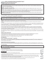 1
1
-
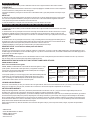 2
2
-
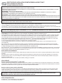 3
3
-
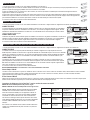 4
4
-
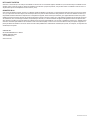 5
5


Suncourt 8682668 Le manuel du propriétaire
- Catégorie
- Ventilateurs ménagers
- Taper
- Le manuel du propriétaire
dans d''autres langues
- English: Suncourt 8682668 Owner's manual