La page est en cours de chargement...

Hearth & Home Technologies • RC200 Multifunction Remote Control • 2166-392 Rev. C • 1/13
1
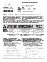
Installation & Operating Instructions
RC200
IntelliFire Plus™ Multifunction Remote Control
Hearth & Home Technologies disclaims any responsibility for,
and the warranty will be voided by, the following actions:
• Installation and use of any damaged system component.
• Modifi cation of the system component.
• Installation other than as instructed by Hearth & Home
Technologies.
• Installation and/or use of any component part not approved
by Hearth & Home Technologies.
Any such action may cause a fi re hazard.
• Read, understand and follow these instructions for safe
installation and operation.
Introduction
The RC200 multifunctional wireless control with dock-
ing station is designed to control constant pilot feature,
fl ame height, blower speed and to turn your gas fi re-
place on and off. The RC200 remote control is only for
use with the Hearth & Home Technologies IntelliFire
Plus™ system (IPI).
FCC Requirements
WARNING! Risk of Fire! Changes or modifi cations to
this unit not expressly approved by the party responsible
for compliance could void the user’s authority to operate
the equipment.
Note: This equipment has been tested and found to
comply with the limits for a Class B digital device, pur-
suant to Part 15 of the FCC Rules. These limits are
designed to provide reasonable protection against
harmful interference in a residential installation. This
equipment generates, uses, and can radiate radio
frequency energy and, if not installed and used in ac-
cordance with the instructions, may cause harmful in-
terference to radio communications. However, there is
no guarantee that interference will not occur in a partic-
ular installation. If this equipment does cause harmful
interference to radio or television reception, which can
be determined by turning the equipment off and on, the
user is encouraged to try to correct the interference by
one or more of the following measures:
• Reorient or relocate the receiving antenna.
• Increase the separation between the equipment and
receiver.
• Connect the equipment into an outlet on a circuit dif-
ferent from that to which the receiver is connected.
• Contact the dealer or an experienced radio TV techni-
cian for help.
Canadian Equipment Requirements
This digital apparatus does not exceed the (Class A/ Class
B) limits for radio noise emissions from digital apparatus
set out in the Radio Interference Regulations of the Cana-
dian Department of Communications. Le present appareil
numerique n’emet pas de bruits radioelectriques depas-
sant les limites applicables aux appareils numeriques (de
la class A/de la class B) prescrites dans le Reglement sur
le brouillage radioelectrique edicte par le ministere des
Communications du Canada.
This device complies with RSS-210 of Industry and Science
Canada. Operation is subject to the following two condi-
tions: (1) this device may not cause interference, and (2)
this device must accept any interference, including interfer-
ence that may cause undesired operation of the device.
Installation Precautions
This control is tested and safe when installed in accor-
dance with this installation manual. Do not install any
components that may be damaged.
Do not modify, disassemble, or substitute any of the com-
ponents included with this kit. Installation of this unit must
be done by a qualifi ed service technician.
Placement of this remote control may affect performance.
An assessment of the space should be done prior to in-
stallation for optimum performance.
Determine Location
Determine the location for the remote control. The selected
location should be in the same space as the gas fi replace
with visual sight of fi replace. The remote control must be
placed within 30 feet of the fi replace but should not be
exposed to extreme heat.
The RC200 is approved for interior installation and should
always be placed under weather resistant cover when used
in exterior applications.
• Keep remote control out of reach of children.

Hearth & Home Technologies • RC200 Multifunction Remote Control • 2166-392 Rev. C • 1/13
2
Figure 3. Mounting Remote Control Housing
5. Close the housing door and press the power button.
The red light illuminates if the battery was properly in-
stalled. See Figure 3.
Fan Installation
• Insert the 3 prong plug from the fan into the receptacle
located in the AUX200 module. See Figure 5.
Figure 4. AUX 200 module installation
RED LED
RED LED
AUX200
AUX200
CABLE
CABLE
AUX200 Module Installation
• Control Module should be set in the OFF position before
any components are installed.
• Insert the 4 hole harness from the AUX200 module into
the 4 pin plug on the control module. See Figure 4.
Figure 2. Remote in Housing
Installation of Remote Control Housing
CAUTION! Risk of Fire! DO NOT install damaged or
modifi ed components. Warranty will be voided if damaged
or modifi ed components are installed.
Kit components: One remote control, two #6 screws, two
wall anchors, one A23 battery and one AUX200 module (if
purchased retail).
1. Remove remote control components from packaging.
2. Remove battery cover from the back of the remote by
sliding it down and install A23 battery.
To prevent unintended operation when not using your fi re-
place for an extended period of time (summer months,
vacation, trips, etc):
• Remove battery from remote control.
• Unplug switching adapter and remove back-up batteries.
3. Secure the remote control housing on a fl at wall sur-
face using the two screws and wall anchors provided.
See Figure 1.
Figure 1. Mounting Remote Control Housing
4. Place remote control inside housing. See Figure 2.

Hearth & Home Technologies • RC200 Multifunction Remote Control • 2166-392 Rev. C • 1/13
3
Figure 6. Programming RC200
REMOTE POSITION
REMOTE POSITION
Figure 5. Plug Fan into AUX200 Module
Programming the RC200 to the Control Module
CAUTION! Risk of burns! DO NOT program the remote
control to the control module when fi replace is hot.
• Verify the ON/OFF/REMOTE switch is in the REMOTE
position. Green LED light will blink three times and beep
once 5 seconds later when ready. See Figure 6.
• Using a small item (such as a paper clip) press and
release the learn button located near the ON/OFF/
REMOTE switch. See Figure 6.
• Control module will beep once and LED will blink green
for 10 seconds.
• While the LED is blinking, press the power button on
the remote control. A double beep will come out of the
control module to indicate that it has been programmed
successfully.
NOTICE: Up to three remote controls can be programmed
into the control module. Simply press a button on the other
remote controls during the 10 second programming process
to add another remote into the system.
To clear memory in the control module, use a small item
(such as a paper clip) to press and release the LEARN
button. Control module will beep once and LED will blink
green for 10 seconds DO NOT press any buttons on the
remote during the ten seconds that the green LED blinks.
The memory will be cleared.
FAN CORD
FAN CORD
• Insert 3 prong plug from AUX200 module into REM/AUX
receptacle of fi replace junction box.
Press the PILOT button to activate or deactivate
the constant pilot.
The control module will beep
once indicating constant pilot has been activat-
ed. A double beep indicates the constant pilot
has been deactivated.
Press the FLAME button to adjust the fl ame
height. The fl ame height can be adjusted to 5
different settings: MAX, HIGH, MEDIUM, LOW,
MIN. Flame height will not be adjustable for fi rst
ten seconds when fi replace is turned on. The
system remembers the previous fl ame height
setting and will automatically adjust to previ-
ous setting after 10 seconds.
Press the FAN button to adjust the fan speed.
The FAN speed can be adjusted to 4 different
settings: HIGH, MED, LOW and OFF. The fan
has a timer built into the control module. After
the fi replace is turned ON the timer will wait for
3 minutes before turning on the fan. In addition,
the fan will remain on for 12 minutes after the
fi replace has been turned OFF. Whenever the
fan is turned ON, the FAN will start up on the
high setting for 10 seconds before adjusting to
the previous user setting.
Function Buttons
Press the POWER button to turn the fi replace
ON and OFF. The fi replace will fi rst ignite the pi-
lot. Once the pilot fl ame is established the main
burner will be lit.
Setting the Child Lock
• Remove battery cover from the back of the remote by
sliding it down. Slide the child lock switch to enable or
disable the child lock feature. See Figure 7.
NOTICE: No functions will be usable until child lock feature
is disabled.
Figure 7. Child Lock Switch
NOTICE: Whenever the fi replace is cycled from OFF to
ON, the main burner will light on high for 10 seconds before
returning to the previous user setting.

Hearth & Home Technologies • RC200 Multifunction Remote Control • 2166-392 Rev. C • 1/13
4
TO JUNCTION
BOX (120V)
CONTROL MODULE
I
S
FLAME
SENSE
WHITE
WHITE
ORANGE
IGNITER
3 PRONG 120VAC
RC200 12V DC
(A23 X 1)
TO JUNCTION
BOX 120VAC
GROUND
ORANGE
(P
ILOT)
GREEN
(MAIN)
BROWN
BLACK
RED
BROWN/RED
OPTIONAL ON/OFF
SWITCH
BATTERY PACK
6V DC
FLAME
MODULATION
AUX200 MODULE
FAN
6V DC
SUPPLY
Figure 8. RC200 Wiring Diagram

Hearth & Home Technologies • RC200 Multifunction Remote Control • 2166-392 Rev. C • 1/13
5
Frequently Asked Questions/Troubleshooting
Please contact your Hearth & Home Technologies
dealer with any questions or concerns.
For the location of your nearest
Hearth & Home Technologies dealer,
please visit www.fi reside.com.
Symptom Possible Cause Corrective Action
Remote control will not transmit
Batteries Verify battery is functional and installed correctly.
Remote control is in Child
Lock mode
Disengage Child Lock mode.
Control module will not take
commands from remote control
Control module is not in
“REMOTE” mode
Ensure module switch is set to REMOTE.
Control module and remote
control are not programmed
to each other
The control module will beep when it successfully receives a
command. If it does not beep, clear module memory and re-
program wall switch.
Control module is
unplugged. In case of
power outage, backup
batteries are depleted or
missing
If red LED light comes on when power button is pressed, verify
that the control module is plugged in the fi replace junction box
located in the controls area. Also verify that the batteries are
installed in the battery pack.
Fan does not turn on when fi replace
is started
Built in time delay
The fi replace must run for three minutes in order for the fan to
engage.
Fan does not turn off when fi replace
turned off
Built in time delay The fan will run for twelve minutes after the fi replace is turned off.
Fireplace shuts down after extended
periods
Built-in timer
The fi replace will automatically shut down after nine hours of
continuous operation if it does not receive a command from
the remote.
Fireplace is on but will not shut off
with the remote control
External wired wall switch
The fi replace cannot be turned off by remote if an external
wired wall switch is installed and in the ON position. Turn ex-
ternal wall switch to OFF.
Remote control or control
module failure
At control module, turn off fi replace by sliding the ON/OFF/RE-
MOTE switch to OFF. Warning! Risk of Fire! Fireplace is hot.
Use caution when accessing module.
Power Outage
• If fi replace battery backup system IS installed at time of
power outage, fi replace operation will not be interrupted.
• If fi replace battery backup system IS NOT installed at
time of power outage, fi replace will shut off. To resume
fi replace operation, install battery backup.
NOTICE: Battery polarity must be correct or module
damage will occur.
Manual Fireplace Shutoff
In the unlikely event that the remote wall switch malfunc-
tions and will not turn off the fi replace, call your dealer
for service assistance. In the meantime, you may choose
one of the following actions to turn off the fi replace:
CAUTION! Risk of burns! Fireplace surfaces are hot
when operating and during cool down. Use care and wear
gloves when opening the front and accessing compo-
nents inside the fi replace.
The fi replace may be manually shut down by one of the
following methods:
Turn off the control module:
• Open or remove the decorative front to access the control
module.
• Move switch to OFF (See Figure 6).
Disconnect power to the control module:
• Open or remove the decorative front to access power
cord to the junction box and/or back-up batteries.
• Unplug the control module and/or remove back-up
batteries.
Shut off gas to the control:
• Open or remove the decorative front and locate the gas
shut-off valve to the left of the gas control.
• Rotate the valve 90 degrees to turn off gas supply.
Turn off power to the fi replace (if back-up batteries are
not installed):
• Locate house circuit breaker for fi replace.
• Turn off the circuit breaker.
1/5