
INSTALLATION INSTRUCTIONS
INSTRUCTIONS D’INSTALLATION
INSTRUCCIONES PARA LA INSTALACIÓN
RANGE TOP 30”-36” ELECTRIC INDUCTION


Dear Customer,
Thank you for purchasing a Fulgor Milano product. Fulgor Milano is
committed to excellence and our signature technologies provide you with
professional tools for your kitchen. One of our central philosophies is
continuous investment in research that is rooted in developing life enhancing
technology. Our goal is to deliver products that are worthy of your family
recipes and that will breathe life into your kitchen, the heart of your home.
We invite you to enjoy your new Fulgor Milano product with same amount
of care and attention that we have put into creating it.
Your Life | Our Passion


EN
1
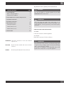
TABLE OF CONTENTS PAGE
1 - Special Warnings 2
Before Starting Installation 2
Mobile Home Installation 2
2 - Product Dimensions and Cutout Requirements 3
3 - Installation Information 8
4 - Installation Information 9
5 - Electrical Connections 10
General information 10
3-Wire branch circuit 11
4-Wire branch circuit 11
6 - Final checklist 12
IMPORTANT: Save these instructions for the local electrical
inspector use.
INSTALLER: Please leave this manual with owner for future
reference.
OWNER: Please keep this manual for future reference.
Pay attention to these symbols present in this manual:
DANGER
You can be killed or seriously injured if you don’t
IMMEDIATELY follow instructions.
WARNING
This is the safety alert symbol. This symbol alerts you to
potential hazards that can kill or hurt you and others. You
can be killed or seriously injured if you don’t follow these
instructions.
READ AND SAVE THESE INSTRUCTIONS.
To installer:
Leave these instructions with the appliance.
To customer:
Retain these instructions for future reference.
WARNING
If the information in this manual is not followed exactly, a fire
or explosion may resulting in product and property damage
and / or personal injury or death.
Do not store or use gasoline or other flammable vapours and
liquids in the vicinity of this or any other appliance.

EN
2
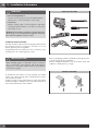
Proper installation is your responsibility.
Have a qualified technician install this rangetop.
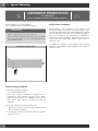
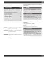
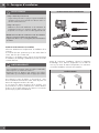
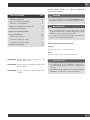
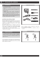
IMPORTANT
- Observe all governing codes and ordinances.
- Write down the model and serial numbers before installing
the range. Both numbers are on the serial rating plate refer
to the illustration below.
LOCATION OF RATING PLATE
Before Starting Installation
• Electrical grounding is required.
See “Electrical Requirements”
• Assure that electrical installation is adequate and in
conformance with National Electrical Code, ANSI/
NFPA 70 - latest edition**, or Canadian Electrical Code,
part 1 C22.1 (latest edition)*** and all local codes and
ordinances.
Copies of the standards listed may be obtained from:
** National Fire Protection Association One Batterymarch Park
Quincy, Massachusetts 02269
*** CSA International 8501 East Pleasant Valley Rd. Cleveland,
OH 44131-5575
Mobile Home Installation
The installation of this appliances must conform to the
Manufactured Home Construction and Safety Standards, Title
24 CFR, Part 3280 (formerly the Federal Standard for Mobile
Home Construction and Safety; Title 24 HUD part 280); or
when such standard is not applicable, the Standard for
Manufactured Home Installations (Manufactured Home Sites,
Communities and Setups), ANSI A225.1 - latest edition, or
with local codes.
In Canada, the installation of this appliances must conform
with the current standards CAN/CSA-Z240 - latest edition, or
with local codes.
1 - Special Warnings
IMPORTANT INSTRUCTION
Special Warnings
Please read all instruction before using this appliance.

EN
3
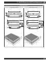
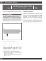
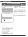
PRODUCT DIMENSIONS
36” Wide Rangetop Models 30” Wide Rangetop Models
35 3/4” (91,0)
29 1/2” (75,1)
min. 24” (61)
max. 25 5/8” (65)
2” (5)
7” (17,9)
2” (5)
2” (5)
7” (17,9)
10” (25,5)
16 3/8” (41,5)
2” (5)
27 3/8” (69,7)
36” (91,4)
29 3/4” (75,8)
29 1/2” (75,1)
30” (76,2)
min. 24” (61)
max. 25 5/8” (65)
2” (5)
7” (17,9)
2” (5)
2” (5)
7” (17,9)
10” (25,5)
16 3/8” (41,5)
2” (5)
27 3/8” (69,7)
27 3/8” (69,7)
35 3/4” (91,0)
7” (17,9)
27 3/8” (69,7)
29 3/4” (75,8)
7” (17,9)
2 - Product Dimensions and Cutout Requirements

EN
4
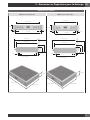
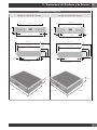
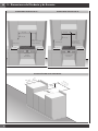
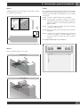
2 - Product Dimensions and Cutout Requirements
CUTOUT REQUIREMENTS 36” CUTOUT REQUIREMENTS 30”
min 18” (45,7)
max 13” (33)
36” (91,4)
min 6” (15,2) min 6” (15,2)
min 30” (76,2)
to bottom of
ventilation hood
Electrical
connection
in this area
min 18” (45,7)
max 13” (33)
30” (76,2)
min 6” (15,2) min 6” (15,2)
min 30” (76,2)
to bottom of
ventilation hood
Electrical
connection
in this area
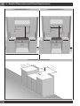
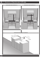
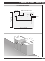
INSTALLATION WITH SEPARATOR SHEET
7” (17
,9)
min 24” (61)
max 25 1/2” (65)
36” (91,4)
30” (76,2)

EN
5
2 - Product Dimensions and Cutout Requirements
INSTALLATION WITH SEPARATOR SHEET
7 7/8” (20)
4 7/8”
(12,5)
7 1/2”
(19,2)
2 3/4” (7)
1 3/4”
(4,5)
1 3/4” (4,5)
7 7/8” (20)
24 1/4” (61,7) / 30 3/8” (77,1)
CUTOUT FOR ELECTRICAL
CUTOUT FOR FIXING BRAKETS
30” (76,2) / 36” (91,4)
max 25 1/2” (65)
min 24” (61)
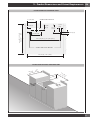
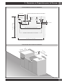
INSTALLATION WITHOUT SEPARATOR SHEET
7” (17,
9
)
2
”
(
5)
2” (
5
)
min 24”
(61)
max 25 1/2” (65)
2” (5)
36” (91,4)
30” (76,2)

EN
6
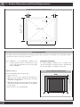
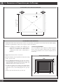
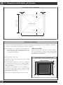
CUTOUT REQUIREMENTS
The surface of the entire back wall above the range and below the hood must be covered with a noncombustible material.
*Consult local code for exact location requirements.
Note: Clearances to non-combustible materials must
conform with local codes or, in the absence of local
codes, with the National Fuel Gas Code, ANSI
Z223.1/NFPA 54.
Minimum clearances:
Above cooking surface (above 36” [91.4 cm])
• Sides 3” (7.6 cm)
• Within 3” (7.6 cm) side clearance, wall cabinets no
deeper than 13” (33.0 cm) must be minimum 18” (45.7
cm) above cooking surface.
• Wall cabinets directly above product must be a minimum
of 30” (76.2 cm) above cooking surface, no deeper than
13” (33.0 cm).
• Rear - 0” with 3” (7.6 cm) backguard.
ADDITIONAL CLEARANCES:
For island installation, maintain 2-½ in. minimum from
cutout to back edge of countertop and 3 in. minimum from
cutout to side edges of countertop (see top view).
FLUSH ISLAND TRIM INSTALLATION
BACK
min 3” (7.6) min 3” (7.6)
min 2 1/2” (6.3)
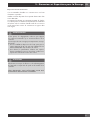
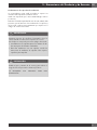
INSTALLATION WITHOUT SEPARATOR SHEET
2” (5) 2” (5)
2” (5)
2” (5)
30” (76,2) / 36” (91,4)
max 25 1/2” (65)
min 24” (61)
EMPTY SPACE
2 - Product Dimensions and Cutout Requirements

EN
7
Vent hood Combinations:
It is recommended that these rangetop be installed in
conjunction with a suitable overhead vent hood.
Install a hood with at least 450 CFM.
Due to the high heat capacity of this unit, particular attention
should be paid to the hood and ductwork installation to assure
it meets local building codes.
WARNING
Clearances to horizontal surfaces above the rangetop,
measured to the cooking surface are below. Failure to
comply may result in fire hazard.
• Installations without a hood require 30” (76 cm) minimum
to combustibles.
• For other installations with a hood, refer to the hood
installation instructions for specific hood clearances.
CAUTION
Due to the weight and size of the range and to reduce the
risk of personal injury or damage to the product:
TWO PEOPLE ARE REQUIRED FOR PROPER INSTALLATION.
2 - Product Dimensions and Cutout Requirements

EN
8
3 - Installation Information
WARNING
• Excessive Weight Hazard
Use two or more people to move and install rangetop.
Failure to do so can result in back or other injury.
• Cut Hazard
Beware of sharp edges. Use the polystyrene ends when
carrying the product. Failure to use caution could result in
minor injury or cuts.
DO NOT obstruct the flow of combustion and ventilation air.
All openings in the wall behind the appliance and in the
floor under the appliance must be sealed.
CHOOSING RANGE LOCATION
Carefully select the location where the rangetop will be placed.
The rangetop should be located for convenient use in the
kitchen, but away from strong drafts.
Strong drafts may be caused by open doors or windows, or by
heating and/or air conditioning vents or fans.
IMPORTANT NOTE
When installing against a combustible surface, a minimum
riser is required for a the rangetop, Follow all minimum
clearances to combustible surfaces shown in the illustration
on the previous pages.
To eliminate the risk of burns or fire by reaching over heated
surface units, cabinet storage space located above the surface
units should be avoided.
If cabinet storage is to be provided, the risk can be reduced by
installing a range hood that projects horizontally a minimum of
inches beyond the bottom of the cabinets.
TOOLS WILL YOU NEED
Remove packaging materials and literature package from the
cooktop before beginning installation.
Remove Installation Instructions from the literature pack and
read them carefully before you begin
MATERIALS PROVIDED

EN
9
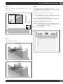
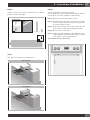
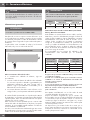
4 - Installation Instructions
STEP 1
Install the backsplash (if provided) by the three screws on the
back and the toe kick
3”9”
STEP 2
Slide the range top into place.
30’’ (76,2 cm)
36’’ (91,4cm)
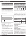
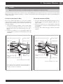
STEP 3
Two clamp brackets are provided with your unit.
After rangetop has been installed into the countertop, install the
brackets on the burner box as shown.
step A place the clamping screws into brackets.
step B attach brackets by using the attachment screws on the
selected location of burner box, tighten screws just
enough to hold brackets in place.
step C position brackets so that they are with the clamp screw
in contact with the counter top bottom.
step D tighten attachment screws securely.
step E check that the front edge of the rangetop is parallel
to the front edge of the countertop tighten the screw
clamping against the countertop.
DO NOT OVER TIGHTEN

EN
10
5 - Electrical Connections
DANGER
Disconnect power before servicing the product.
Failure to do so could result in death or electrical shock.
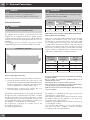
General information
WARNING
The models may be powered at 240V or 208V.
This rangetop does not require a neutral connection. If the
rangetop is to be completely enclosed in a cabinet, feed the
cooktop cable through the opening in the cabinet. Make the
electrical connection following the appropriate steps for your
installation.
Your rangetop must be connected to the proper electrical
voltage and frequency as specified in the table on the right.
LOCATION OF SERIAL TAG
Connect with copper wire only
If the house has aluminum wiring, follow the procedure below:
1. Connect the aluminum wiring to the copper wire by using
special connectors designed and Underwriters Laboratories-
listed for joining copper to aluminum. Follow the electrical
connector manufacturer’s recommended procedure.
2. Aluminum/copper connection must conform with local
codes and industry- accepted wiring practices.
The flexible conduit (supplied) 3 feet long (100 cm) located at
the right rear of the cooktop bottom box should be connected
directly to junction box. Do not cut the conduit. A U.L - or CSA
- listed conduit connector must be provided at each end of the
power supply cable (at the cooktop and at the junction box.) A
time delay fuse or circuit breaker is recommended.
Do not ground to a gas pipe. Do not have a fuse in the
grounding or neutral circuit.
Fuse both supply (phase) lines.
WARNING
Improper connection of aluminum house wiring to the copper
leads can result in a serious problem.
Model
Power Supply
240 V 60 Hz 208 V 60 Hz
30“
7.20 kW 30 A 6.45 kW 31 A
36“
10.80 kW 45 A 9.80 kW 47 A
National Fire Protection Association Batter/march Park
Quincy, Massachusetts 02269
A three-wire, single phase, 240 Volt 60 cycle electrical system
(properly circuit protected to meet Local Codes of NFPA
No.70) must be provided. Unit must be properly grounded
in accordance with local wiring code. The chart below
recommends the minimum circuit protector and wire size if the
appliance is the only unit on the circuit. If smaller sizes of wire
are used, the unit efficiency will be reduced and a fire hazard
may be created. It is advisable that the electrical wiring and
hookup be accomplished by a competent electrician.
Recommended Minimum
kW Rating on
serial plate
Circuit protection
in amperes
Wire size
(AWG)
0.1 - 4.8 20 12
4.9 - 6.9 30 10
7.0 - 9.9 40 8
10.0 - 11.9 50 8
12.0 - 14.9 60 6
Be sure your appliance is properly installed and grounded by a
qualified technician.
Ask your dealer to recommend a qualified technician or an
authorized repair service.
This rangetop does not require a neutral connection.
If the cooktop Is to be completely enclosed In a cabinet, feed the
cooktop cable through the opening in the cabinet.
Make the electrical connection following the appropriate steps
for your installation.
This appliance is manufactured with a green ground wire
connected to the cooktop chassis.
After making sure that the power has been turned off, connect
the flexible conduit from the appliance to the junction box
using a U.L. listed conduit connector.
The instructions provided below present the most common way
of connecting the cooktops.
Your local codes and ordinances, of course, take precedence
over these instructions. Complete electrical connections
according to local codes and ordinances

EN
11
DANGER
Risk of Electric Shock, frame grounded to neutral of appliance through a link.
Grounding through the neutral conductor is prohibited for new branch-circuit installations (1996 NEC); mobile homes; and
recreational vehicles, or in an area where local codes prohibit grounding through the neutral conductor.
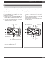
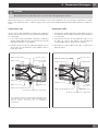
3-Wire branch circuit
Where local codes allow the connection of ground wire from
the cooktop to the branch circuit neutral wire (gray or white
colored wire) proceed as follows:
1. If local codes permit, connect the green GROUND wire
from the cooktop to the branch circuit neutral wire (gray or
white colored wire).
2. Connect the red and black leads from the cooktop to the
corresponding leads in the junction box.
Cable from power supply
Red Wires
White Wires
Bare or green wires
3-Wire cable from cooktop
Where local codes permit connecting the frame-ground
conductor to the neutral (white) junction box wire.
(Not used for Canadian installations)
Junction box
Twist-on connector
Black wires
U.L.-or CSA-listed conduit connector
4-Wire branch circuit
1. Connect the green ground wire from the cooktop to the
ground wire in the junction box (bare or green colored
wire).
2. Connect the red and black leads from the cooktop to the
corresponding leads in the junction box.
3. Terminate and insulate the neutral (gray or white colored
wire) in the junction box.
Red wires
Bare or green wires
3-Wire cable from cooktop
Twist-on
connector
Black wires
U.L. - or CSA-listed conduit connector
Junction box
White wire
Cable from power supply
5 - Electrical Connections

EN
12
6- Final checklist
To prevent improper connections leading to damage of
electrical components and so voiding the warranty, the
following steps must be performed:
1. Check the electrical requirements and make sure you have
the correct electrical supply and that the range is properly
grounded.
2. Before the range is connected, turn on the power supply.
3. Check power at the junction box wires using a voltmeter
having a range of 0-250 VAC.
IMPORTANT
Leave these INSTALLATION instructions as well as the USE
AND CARE MANUAL with the owner.

FR
1
TABLES DES MATIERES PAGE
1 - Avertissement Spéciaux 2
Avant de Procéder à l’Installation 2
Installation autocaravane 2
2 - Dimensions et Dispositions pour la Découpe 3
3 - Consignes d’installation 8
4 - Instructions d’Installation 9
5 - Connexions Electriques 10
Informations générales 10
Connexion à 3 fils 11
Connexion à 4 fils 11
6 - Liste de vérification finale 12
IMPORTANT: Gardez ces instructions pour une utilization
d’inspection électrique locale
INSTALLATEUR: Veuillez laisser ce manuel au propriétaire
pour de futures références.
PROPRIETAIRE: Veuillez garder ce manuel pour de futures
références.
Veuillez prêter attention à ces symboles que vous rencontrerez
dans ce manuel :
DANGER
Si vous ne suivez pas IMMEDIATEMENT ces instructions,
vous courez le risque de mourir ou d’être sérieusement
blessé.
AVERTISSEMENT
Ce symbole signifie que la sécurité est en danger. Il signale
les risques potentiels qui peuvent entraîner la mort ou des
blessures à l’opérateur ou aux autres.
Si vous ne suivez pas ces instructions à la lettre, vous courez
le risque de mourir ou d’être sérieusement blessé.
BIEN LIRE CES INSTRUCTIONS ET LES CONSERVER.
À l’installateur :
Laissez ces instructions avec l’appareil.
Au client :
Gardez ces instructions comme référence future.
AVERTISSEMENT
Le respect minutieux des indications fournies dans ce manuel
est indispensable pour éviter le risque de feu ou d’explosion
susceptible d’endommager les biens et les produits et de
provoquer des blessures, voire même la mort.
Ne pas stocker ou utiliser de l’essence ou d’autres liquides
inflammables à proximité de cet appareil ou de tout autre
appareil électroménager.

FR
2
Il est de votre responsabilité d’installer l’appareil correctement.
Confiez l’installation de cette cuisinières à un technicien qualifié.
AVERTISSEMENT
- Respecter les règlements et ordonnances en vigueur.
- Avant l’installation de la cuisinière, noter le modèle et
les numéros de série. Les deux numéros se trouvent sur
la plaque de données dans la position indiquée dans la
figure ci-dessous.
POSITION DE LA PLAQUE SIGNALÉTIQUE
Avant de Procéder à l’Installation
• L’appareil doit nécessairement être relié à la terre.
Voir «Conditions requises électricité».
• Veuillez vous assurer que l’installation électrique est
adéquate et conforme à la Réglementation Électrique
Nationale ANSI/NFPA 70 – dernière édition** ou à la
Réglementation Électrique du Canada, C22.1 – 1982 et
C22.2 N° 01982 (ou dernière édition)*** et à tous les
règlements et ordonnances en vigueur localement.
Vous pouvez demander une copie des standards répertoriés à:
** National Fire Protection Association One Batterymarch Park
Quincy, Massachusetts 02269
*** CSA International 8501 East Pleasant Valley Rd. Cleveland,
OH 44131 – 5575
Installation autocaravane
L’installation de cette table de cuisson doit être conforme
aux Normes de Construction et de Sécurité des Habitations,
titre 24 CFR, Partie 3280 (jadis la Norme Fédérale pour la
Construction et la Sécurité des Autocaravanes; titre 24HUD
partie 280); ou lorsque de telles normes ne sont pas
applicables, la Norme pour les Installations des Habitations
(Emplacements, Communautés et Structures Habitations),
ANSI 225.1 - dernière édition ou aux réglementations locales.
Au Canada, l’installation de cette table de cuisson doit être
conforme aux normes en vigueur CAN/CSA-Z240 - dernière
édition ou aux réglementations locales.
1 - Avertissement Spéciaux
INSTRUCTION IMPORTANT
Avertissement Spéciaux
Veuillez lire les instructions avant toute utilisation

FR
3
2 - Dimensions et Dispositions pour la Découpe
DIMENSIONS DU PRODUIT
Modèles de cuisinière 36” Modèles de cuisinière 30”
35 3/4” (91,0)
29 1/2” (75,1)
min. 24” (61)
max. 25 5/8” (65)
2” (5)
7” (17,9)
2” (5)
2” (5)
7” (17,9)
10” (25,5)
16 3/8” (41,5)
2” (5)
27 3/8” (69,7)
36” (91,4)
29 3/4” (75,8)
29 1/2” (75,1)
30” (76,2)
min. 24” (61)
max. 25 5/8” (65)
2” (5)
7” (17,9)
2” (5)
2” (5)
7” (17,9)
10” (25,5)
16 3/8” (41,5)
2” (5)
27 3/8” (69,7)
27 3/8” (69,7)
35 3/4” (91,0)
7” (17,9)
27 3/8” (69,7)
29 3/4” (75,8)
7” (17,9)

FR
4
2 - Dimensions et Dispositions pour la Découpe
DISPOSITIONS POUR LA DÉCOUPE 36” DISPOSITIONS POUR LA DÉCOUPE 36”
min 18” (45,7)
max 13” (33)
36” (91,4)
min 6” (15,2) min 6” (15,2)
min 30” (76,2)
de distance avec le fond
de la hotte d'aération
Branchement
électrique
dans cette zone
min 18” (45,7)
max 13” (33)
30” (76,2)
min 6” (15,2) min 6” (15,2)
min 30” (76,2)
de distance avec le fond
de la hotte d'aération
Branchement
électrique
dans cette zone
INSTALLATION AVEC PLAQUE DE SEPARATION
7” (17
,9)
min 24” (61)
max 25 1/2” (65)
36” (91,4)
30” (76,2)
La page charge ...
La page charge ...
La page charge ...
La page charge ...
La page charge ...
La page charge ...
La page charge ...
La page charge ...
La page charge ...
La page charge ...
La page charge ...
La page charge ...
La page charge ...
La page charge ...
La page charge ...
La page charge ...
La page charge ...
La page charge ...
La page charge ...
La page charge ...
La page charge ...
La page charge ...
La page charge ...
La page charge ...
-
 1
1
-
 2
2
-
 3
3
-
 4
4
-
 5
5
-
 6
6
-
 7
7
-
 8
8
-
 9
9
-
 10
10
-
 11
11
-
 12
12
-
 13
13
-
 14
14
-
 15
15
-
 16
16
-
 17
17
-
 18
18
-
 19
19
-
 20
20
-
 21
21
-
 22
22
-
 23
23
-
 24
24
-
 25
25
-
 26
26
-
 27
27
-
 28
28
-
 29
29
-
 30
30
-
 31
31
-
 32
32
-
 33
33
-
 34
34
-
 35
35
-
 36
36
-
 37
37
-
 38
38
-
 39
39
-
 40
40
-
 41
41
-
 42
42
-
 43
43
-
 44
44


