Fulgor Milano F6PIR365S1 Guide d'installation
- Catégorie
- Fours
- Taper
- Guide d'installation

INSTALLATION INSTRUCTIONS
INSTRUCTIONS D’INSTALLATION
INSTRUCCIONES PARA LA INSTALACIÓN
PRO-RANGE 30” - 36” ELECTRIC INDUCTION


EN
1
TABLE OF CONTENTS PAGE
1 - Special Warnings 2
Before Starting Installation 2
Mobile Home Installation 2
2 - Product Dimensions and Cutout Requirements 3
Anti-Tip Bracket Installation 5
3 - Installation Information 6
4 - Installation Instructions 7
5 - Electrical supply 9
6 - Electrical connections 11
4-wire connection 12
3-wire connection 12
Direct Electrical Connection to the Circuit Breaker,
Fuse Box or Junction Box 13
7 - Final checklist 14
IMPORTANT: Save these instructions for the local electrical
inspector use.
INSTALLER: Please leave this manual with owner for future
reference.
OWNER: Please keep this manual for future reference.
Pay attention to these symbols present in this manual:
DANGER
You can be killed or seriously injured if you don’t
IMMEDIATELY follow instructions.
WARNING
This is the safety alert symbol. This symbol alerts you to
potential hazards that can kill or hurt you and others. You
can be killed or seriously injured if you don’t follow these
instructions.
READ AND SAVE THESE INSTRUCTIONS.
To installer:
Leave these instructions with the appliance.
To customer:
Retain these instructions for future reference.
WARNING
If the information in this manual is not followed exactly, a fire
or explosion may resulting in product and property damage
and / or personal injury or death.
Do not store or use gasoline or other flammable vapours and
liquids in the vicinity of this or any other appliance.

EN
2
Proper installation is your responsibility. Have a qualified
technician install this range.
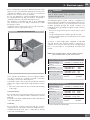
IMPORTANT
- Observe all governing codes and ordinances.
- Write down the model and serial numbers before installing
the range. Both numbers are on the serial rating plate refer
to the illustration below.
LOCATION OF RATING PLATE
Before Starting Installation
• Check location where range will be installed. The location
should be away from strong drafty areas, such as windows,
doors and strong heating vents or fans.
• Electrical grounding is required. See “Electrical
Requirements”
• Assure that electrical installation is adequate and in
conformance with National Electrical Code, ANSI/
NFPA 70 - latest edition**, or Canadian Electrical Code,
part 1 C22.1 (latest edition)*** and all local codes and
ordinances.
Copies of the standards listed may be obtained from:
** National Fire Protection Association One Batterymarch Park
Quincy, Massachusetts 02269
*** CSA International 8501 East Pleasant Valley Rd. Cleveland,
OH 44131-5575
Mobile Home Installation
The installation of this appliances must conform to the
Manufactured Home Construction and Safety Standards, Title
24 CFR, Part 3280 (formerly the Federal Standard for Mobile
Home Construction and Safety; Title 24 HUD part 280); or
when such standard is not applicable, the Standard for
Manufactured Home Installations (Manufactured Home Sites,
Communities and Setups), ANSI A225.1 - latest edition, or
with local codes.
In Canada, the installation of this appliances must conform
with the current standards CAN/CSA-Z240 - latest edition, or
with local codes.
1 - Special Warnings
IMPORTANT INSTRUCTION
Special Warnings
Please read all instruction before using this appliance.

EN
3
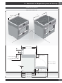
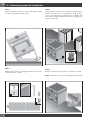
PRODUCT DIMENSIONS
30” Wide Range Models
29 3/4” (75,8)
35 3/4” (91,0)
35
3/4
”
(9
1,0)
”
7 3/8” (18.7)
1 3/8” (3.5)
3 3/8” (8.5)
TO
27 1/4” ( 69.1)
25 3/4” ( 65.4)
47 3/4” (121.4)
27 1/2” (69.7)
29 3/4” (75.6)
3/8” (1)
Max. 37 1/4” (94.7)
Min. 35 3/8” (89.8)
1" ( 2.5)
3" ( 7.6) [optional]
9" (22.8) [optional]
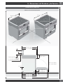
2 - Product Dimensions and Cutout Requirements

EN
4
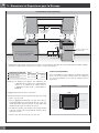
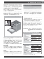
2 - Product Dimensions and Cutout Requirements
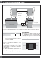
CUTOUT REQUIREMENTS
ELECTRICGAS
B B
*Suggested location
of utilities
2” (5.1) max. protusion from
wall for gas or electrical supply
3” (7.6)
4” 3/4 (12.3)
A
Min. 18” (45.7)
Min. 30” (76.2)
To bottom of
ventilation hood
Min. 18” (45.7)
Max. 13” (33)
Min. 6”
(15.2)
Min. 6”
(15.2)
C
The surface of the entire back wall above the range and below the hood must be covered with a noncombustible material.
*Consult local code for exact location requirements.
OPENING WIDTH A & C B
Range 30” 30" (76.2) 6” (15.2)
Range 36” 36" (91.4) 7” (17.8)
Note: Clearances to non-combustible materials must
conform with local codes or, in the absence of local
codes, with the National Fuel Gas Code, ANSI
Z223.1/NFPA 54.
Minimum clearances:
Above cooking surface (above 36” [91.4 cm])
• Sides 3” (7.6 cm)
• Within 3” (7.6 cm) side clearance, wall cabinets no
deeper than 13” (33.0 cm) must be minimum 18” (45.7
cm) above cooking surface.
• Wall cabinets directly above product must be a minimum
of 30” (76.2 cm) above cooking surface.
• Rear - 0” with 3” (7.6 cm) backguard.
ADDITIONAL CLEARANCES:
For island installation, maintain 2-½ in. minimum from
cutout to back edge of countertop and 3 in. minimum from
cutout to side edges of countertop (see top view).
FLUSH ISLAND TRIM INSTALLATION
BACK
min 3” (7.6) min 3” (7.6)
min 2 1/2” (6.3)

EN
5
2 - Product Dimensions and Cutout Requirements
Before moving the range, protect any finished flooring and
secure oven door(s) closed to prevent damage.
Vent hood Combinations:
It is recommended that these ranges be installed in conjunction
with a suitable overhead vent hood.
Install a hood with at least 450 CFM.
Due to the high heat capacity of this unit, particular attention
should be paid to the hood and ductwork installation to assure
it meets local building codes.
WARNING
Clearances to horizontal surfaces above the range, measured
to the cooking surface are below. Failure to comply may
result in fire hazard.
• Installations without a hood require 30” (76) minimum to
combustibles.
• A custom hood installation with exposed horizontal
combustible surfaces must have an Auto-On feature.
• For other installations with a hood, refer to the hood
installation instructions for specific hood clearances.
CAUTION
These ranges weigh up to 400 pounds. Some disassembly
will reduce the weight considerably. Due to the weight and
size of the range and to reduce the risk of personal injury or
damage to the product:
TWO PEOPLE ARE REQUIRED FOR PROPER INSTALLATION.
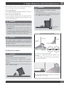
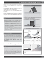
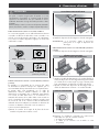
Anti-Tip Bracket Installation
WARNING
Tip Over Hazard
A child or adult can tip the range and be killed.
Ensure the anti-tip bracket is engaged when the range is
moved.
Do not operate range without anti-tip bracket installed and
engaged.
Failure to follow these instructions can result in death or serious
burns to children and adults.
WARNING
To verify the anti-tip bracket is installed and engaged:
• Slide range forward.
• Look for the anti-tip bracket securely attached to floor or wall.
• Slide range back so rear range foot is under anti-tip bracket.
• See installation instructions for details.
Range Foot
Anti-Tip Bracket
ANTI-TIP BRACKET INSTALLATION
ANTI-TIP
BRACKET
FLUSH
CABINET
SIDEWALL
BACKWALL
WALL
ANCHOR
For Concrete or Cement Construction:
You must use appropriate fastening hardware (not
provided).
Secure the bracket to the wall and/or floor with at least 4
wood screws (provided).
The anti-tip bracket should be inserted into the opening on
the anti-tip brace on the range.

EN
6
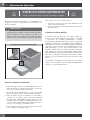
3 - Installation Information
WARNING
• Excessive Weight Hazard
Use two or more people to move and install range.
Failure to do so can result in back or other injury.
• Cut Hazard
Beware of sharp edges. Use the polystyrene ends when
carrying the product. Failure to use caution could result in
minor injury or cuts.
Do not obstruct the flow air at the oven vent nor around the
base or beneath the lower front panel of the range. Avoid
touching the vent openings or nearby surfaces as they may
become hot while the oven is in operation.
CHOOSING RANGE LOCATION
Carefully select the location where the range will be placed.
The range should be located for convenient use in the kitchen,
but away from strong drafts.
Strong drafts may be caused by open doors or windows, or by
heating and/or air conditioning vents or fans.
IMPORTANT NOTE
When installing against a combustible surface, a minimum
riser is required for a the range, Follow all minimum
clearances to combustible surfaces shown in the illustration
on the previous pages.
Before moving the range, protect any finished flooring and
secure oven door(s) closed to prevent damage.
Do not lift or carry the range door by the door handle.
To eliminate the risk of burns or fire by reaching over heated
surface units, cabinet storage space located above the surface
units should be avoided. If cabinet storage is to be provided,
the risk can be reduced by installing a range hood that projects
horizontally a minimum of inches beyond the bottom of the
cabinets.
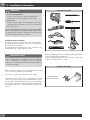
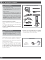
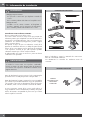
TOOLS WILL YOU NEED
Remove packaging materials and literature package from the
cooktop before beginning installation.
Remove Installation Instructions from the literature pack and
read them carefully before you begin
MATERIALS PROVIDED
ANTI-TIP BRACKET
BRACE ABD SCREWS

EN
7
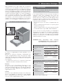
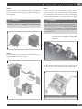
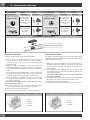
4 - Installation Instructions
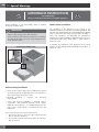
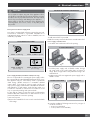
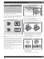
STEP 1
Cut the banding and remove the appliance from the pallet by a
hand-truck inserting the blade under the foam base.
CAUTION
Stand clear. The ends of the cut banding may snap toward you.
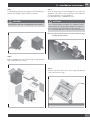
STEP 2
Remove Installation Instructions from the top of range and read
them carefully before you begin.
STEP 3
Move the range indoors before installing the legs, position the
appliance near its final location as the legs are not suitable for
moving the appliance over long distances.
Legs are packed in the cardboard top pack.
CAUTION
Doors and passageways leading to the installation location
require at least 31” opening. If the opening is less than 31”,
the oven door(s) and control knobs must be removed.
(see Use & Care manual for oven door removal instructions).
Note: the legs with collar must be mounted on the back of range
to engage the anti tip device.
STEP 4
With the foam base still in place, tilt the range laterally and
screw in the first pair of legs.

EN
8
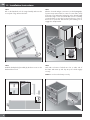
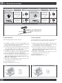
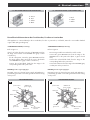
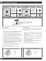
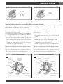
STEP 5
Pull out the hand-truck, tilt the range laterally and insert the
second pair of legs. Remove the base
STEP 6
Install the backsplash (if provided) by the three screws on the
back and the toe kick
3”9”
STEP 7
After the electrical and gas connections (see both paragraphs
for instructions) measure the four corners in cutout area to verify
if flooring is level. Adjust the leveling legs to the desired height
and ensure range is level. Turn the bottom section of each leg
counter-clockwise to raise the leg and clock wise to lower it.
Ensure floor is protected. Slide unit into place making sure to
engage the anti-tip bracket.
STEP 8
Hook tabs on bottom of toekick into slots on either side of
the frame and rotate up until clips at top of toekick engage
securely.
NOTE: Be sure the toekick snaps securely.
4 - Installation Instructions

EN
9
5 - Electrical supply
Before installing the oven have a qualified electrician verify
that your home is provided with adequate electrical service
and that the addition of the oven will not overload the
branch circuit on which it is to be installed.
Be sure your appliance is properly installed and grounded
by a qualified technician. Ask your dealer to recommend a
qualified technician or an authorized repair service.
This appliance is manufactured with a green GROUND
wire connected to the oven chassis Junction Box or Wall
Receptacle Location.
Suggested location of the junction box or wall receptacle is
showed in “Cutout requirements” Figure.
LOCATION OF RATING PLATE
Your local codes and ordinances, of course, take precedence
over these instructions. Complete electrical connections
according to local codes and ordinances.
A UL listed conduit connector must be provided at each end
of the power supply conduit (at the range and at the junction
box).
• Wire sizes and connections must conform with the rating
of the range.
In the United States:
Be sure that the electrical and grounding connections and
also wire size are adequate and in conformance with the
National
Electrical Code, ANSI/ NFPA 70-latest edition and all local
codes and ordinances.
In Canada:
Be sure that the electrical connection and wire size are
adequate and in conformance with CSA Standard C22.1,
Canadian Electrical Code, Part 1 - latest edition, and all
local codes and ordinances.
WARNING
Risk of Electric Shock, frame grounded to neutral of
appliance through a link
Grounding through the neutral conductor is prohibited for
new branch-circuit installations (1996 NEC); mobile homes;
and recreational vehicles, or in an area where local codes
prohibit grounding through the neutral conductor. For
installations where grounding through the neutral conductor
is prohibited:
- Disconnect the ground from the neutral at free end of
conduit;
- Use grounding terminal or lead to ground unit; and
- Connect neutral terminal or lead to branch circuit neutral
in usual manner.
A 3-wire* or 4-wire single phase 120/240 or 120/208
Volt, 60 Hz AC only electrical supply is required on a
separate circuit fused on both sides of the line (time-delay
fuse or circuit breaker is recommended). DO NOT fuse
neutral.
NOTE: FOR USE WITH 208 V, 60 HZ SUPPLY VOLTAGE,
SEE CONNECTING TO 208 VOLT CIRCUIT.
ELECTRICAL REQUIREMENTS 30”
Electrical Supply 120-240V or 120-208V, 60 Hz
Service 50 amp dedicated circuit
Total Amps 120/240V 45.8 Amps
120/208V 48.5 Amps
Max Connected Load 120/240V 11.00 kW
120/208V 10.00 kW
Min Supply Wire L1, L2, ground 8 AWG
Neutral 10 AWG
ELECTRICAL REQUIREMENTS 36”
Electrical Supply 120-240V or 120-208V, 60 Hz
Service 50 amp dedicated circuit
Total Amps 120/240V 61.0 Amps
120/208V 63.0 Amps
Max Connected Load 120/240V 14.60 kW
120/208V 13.30 kW
Min Supply Wire L1, L2, ground 8 AWG
Neutral 10 AWG
(*) Power limitation at 50.0 Amps

EN
10
WARNING
ELECTRICAL SHOCK HAZARD
• The electrical power to the appliance branch circuit
must be shut off while line connections are being made.
• Do not use an extension cord with this appliance.
• Electrical ground is required on this appliance.
• The free end of the green wire (the ground wire) must
be connected to a suitable ground. This wire must
remain grounded to the appliance.
• If cold water pipe is interrupted by plastic, non metallic
gaskets, union connections or other insulating materials,
DO NOT use for grounding.
• DO NOT ground to a gas pipe.
• DO NOT have a fuse in the NEUTRAL or GROUNDING
circuit. A fuse in the NEUTRAL or GROUNDING circuit
could result in an electrical shock.
• Check with a qualified electrician if you are in doubt as
to whether the appliance is properly grounded.
• Failure to follow these instructions could result in serious
injury or death.

EN
11
6 - Electrical connections
CAUTION
Do not repair or replace any part of the appliance unless
specifically recommended in the manual. All other servicing
should be done by a qualified technician. This may reduce
the risk of personal injury and damage to the appliance.
Never modify or alter the construction of the appliance by
removing panels, wire covers, screws, or any other part of
the product.
Factory Connected Power Supply Cord
Your range is equipped with a factory-connected power cord.
Cord must be connected to a grounded 120/240 volt or
120/208 volt range outlet. If no outlet is available, have one
installed by a qualified.
PLUG POWER SUPPLY CORD
NEMA 14-50P Plug NEMA 14-50R Receptacle
NEMA 10-50P Plug
(for US only)
NEMA 10-50R Receptacle
(for US only)
Power Supply Cord Kit or Flexible Conduit (for US only)
The user is responsible for connecting the power supply cord to
the connection block located behind the back panel access cover.
This appliance may be connected by means of permanent
“hard wiring” (flexible armored or nonmetallic shielded
copper cable), or by means of a power supply cord kit. Use
only a power supply cord kit rated at 125/250 volts minimum
and marked for use with ranges. Cord must have either 3 or
4 conductors. Terminals on end of wires must either be closed
loop or open-end spade lugs with upturned ends.
For 30” and 36” ranges use a power supply cord kit rated at
minimum 50A that is marked for use with nominal 1-3/8 in
(34.93 mm) diameter connection openings.
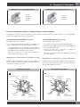
1) Disconnect power.
2) Remove the terminal block cover screws located on the back
of the range.
LOCATION OF ELECTRICAL CONNECTION
3) Add strain relief if not provided.
NOTE: If necessary remove the knockout to insert the strain relief.
Power supply cord strain relief
• Assemble a UL listed strain relief in the opening.
UL LISTED STRAIN RELIEF
• Feed the power supply cord or flexible conduit through
the strain relief in the cord/conduit plate on bottom of
range. Allow enough slack to easily attach the wiring to the
terminal block.
• Tighten strain relief screw against the power supply cord or
flexible conduit.
POWER SUPPLY CORD FLEXIBLE CONDUIT
4) Complete installation following instructions for your type of
electrical connection:
• 4-wire (recommended)
• 3-wire (if 4-wire is not available)

EN
12
4-wire connection
Part of metal ground strap must be removed.
1) Use Phillips screwdriver to remove the ground-link screw
from the back of the range. Save the ground-link screw and
the end of the ground link under the screw.
2) Feed the power supply cord through the strain relief in the
cord/conduit plate on bottom of range. Allow enough slack
to easily attach the wiring to the terminal block.
3) Use Phillips screwdriver to connect the green ground wire
from the power supply cord to the range with the ground-
link screw. The ground wire must be attached first.
4) Use 3/8” nut driver to connect the neutral (white) wire to the
enter terminal block post with one of the 10-32 hex nuts.
(Refer to the “Electric Connection Options” table to see the
appropriate connection type)
5) Connect line 1 (black) and line 2 (red) wires to the outer
terminal block posts with 10-32 hex nuts.
6) Securely tighten hex nuts.
7) Replace terminal block access cover.
“30” INDUCTION RANGE 4-WIRE CONNECTION
A
D
C
B
A. Red
B. White
C. Green
D. Black
3-wire connection
Use this method only if local codes permit connecting chassis
ground conductor to neutral wire of power supply cord:
1) Feed the power supply cord through the strain relief in the
cord/conduit plate on bottom of range. Allow enough slack
to easily attach the wiring to the terminal block.
2) Use 3/8 nut driver to connect the neutral (white) wire to the
center terminal block post with one of the 10-32 hex nuts.
(Refer to the “Electric Connection Options” table to see the
appropriate connection type)
3) Connect line 1 (black) and line 2 (red) wires to the outer
terminal block posts with 10-32 hex nuts.
4) Securely tighten hex nuts.
5) Replace terminal block access cover.
“30” INDUCTION RANGE 3-WIRE CONNECTION
A
C
B
A. Red
B. White
C. Black
6 - Electrical connections
ELECTRICAL CONNECTION OPTIONS
IF YOUR HOME HAS AND YOU WILL BE
CONNECTING TO:
CONNECTION
TYPE:
IF YOUR HOME HAS AND YOU WILL BE
CONNECTING TO:
CONNECTION
TYPE:
4-wire receptacle
(NEMA type 14-50R)
A UL listed, 250-
volt minimum,
50-amp, range
power supply
cord
3-wire receptacle
(NEMA type 10-50R)
A UL listed, 250-
volt minimum,
50-amp, range
power supply
cord
4-wire direct
A fused
disconnect or
circuit breaker
box
3-wire direct
A fused
disconnect or
circuit breaker
box
(12.7 cm)
5"
(12.7 cm)
5"
TERMINAL BLOCK - GROUND STRAP
A. Metal ground strap
B. Ground-link screw

EN
13
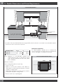
“36” INDUCTION RANGE 4-WIRE CONNECTION
A
C
B
D
A. Green
B. Red
C. White
D. Black
“36” INDUCTION RANGE 3-WIRE CONNECTION
A
B
C
A. Red
B. White
C. Black
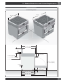
3-WIRE BRANCH CIRCUIT (for US only)
Refer to Figure A:
where local codes allow the connection of GROUND wire from
the range to the branch circuit NEUTRAL wire (gray or white
colored wire):
- If local codes permit, connect the green GROUND wire from
the range and the white wire from the oven to the branch
circuit NEUTRAL wire (gray or white colored wire).
- Connect the red and black leads from the range to the
corresponding leads in the junction box.
DO NOT ground to a gas supply pipe.
DO NOT connect to electrical power supply until appliance is
permanently grounded. Connect the ground wire before turning
on the power.
GROUNDED NEUTRAL
White wires
Cable from
power supply
Junction box
UL listed conduit
connector
Red wires
Black wires
Cable
from oven
Bare or
green wire
A
4-WIRE BRANCH CIRCUIT (for US only)
Refer to Figure B:
- Disconnect ground from neutral at free end of conduit.
- Connect the green GROUND wire from the range to the
GROUND wire in the junction box (bare or green colored
wire).
- Connect the red and black leads from the range to the
corresponding leads in the junction box.
- Connect the white wire from the range to the NEUTRAL (gray
or white) wire in the junction box.
DO NOT ground to a gas supply pipe.
DO NOT connect to electrical power supply until appliance is
permanently grounded. Connect the ground wire before turning
on the power.
UNGROUNDED NEUTRAL
Red wires
Junction box Cable from
power supply
White wires
Black wires
UL listed conduit
connector
Cable
from oven
Bare or
green wire
B
Direct Electrical Connection to the Circuit Breaker, Fuse Box or Junction Box
If the appliance is connected directly to the circuit breaker, fuse box or junction box, use flexible, armored or non metallic sheathed
copper cable (with grounding wire).
6 - Electrical connections

EN
14
7 - Final checklist
To prevent improper connections leading to damage of
electrical components and so voiding the warranty, the
following steps must be performed:
1. Check the electrical requirements and make sure you have
the correct electrical supply and that the range is properly
grounded.
2. Before the range is connected, turn on the power supply.
3. Check power at the junction box wires using a voltmeter
having a range of 0-250 VAC. If you have installed the
oven for use on 240 Volt supply, you should find that the
voltage reading between the black and red wires (Line to
Line) should be 220 to 240 Volts. If you have modified the
range(s) for use on 208 Volt, the voltage reading between
the black and red wires should be 190 to 208 Volts.
4 Connect the range to the power supply.
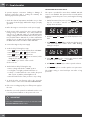
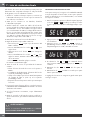
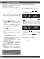
5. Set the clock by following these steps:
• Press
TIME
key twice until the display shows “SET TIME”.
• Immediately press
+
or
-
keys to set hours.
• Press
TIME
key again to change minutes.
• Immediately press
+
or
-
keys to set minutes, hold to
change by ten (10) minutes step.
• Press
TIME
key or wait for a few seconds.
Clock is now set.
6. Test the bake mode by following this step:
• Move cooking mode knob to “BAKE” position.
• Cooling fan, oven lights, preheat led will turn on.
• A beep is sounded when the oven reaches the preset
350 °F (175 °C) and the preheat light turn off.
• Move the knob back to “OFF” position to stop cooking.
7. To check the other oven functions refer to the “Using the
Oven Controls” section of the USE AND CARE MANUAL.
8. If the oven is working properly, turn off the power supply to
the oven.
9. Place the cover on the junction box and make sure the cover
is securely fastened and turn on the power to the oven.
IMPORTANT
Leave these INSTALLATION instructions as well as the USE
AND CARE MANUAL with the owner.
CONNECTING TO 208 VOLT CIRCUIT
This option is provided for areas where standard 240 Volt
service is not available. This option must be accessed with the
appliance connected to power source, and using the following
sequence:
1. Within five minutes from power up, hold
MENU
and
TIME
keys for 3 seconds to enter the user option menu. The
display shows as follows:
2. Hold then
TIME
and
LIGHT
keys until the display becomes
dark.
3. Hold
MENU
and
LIGHT
further, until the time display shows
“Volt” and temperature module shows “240” blinking,
waiting for an input.
4. Using
+
or
-
keys, the control toggles between 240V
and 208V options. Hold
MENU
to confirm.
5. Hold
TIME
and
LIGHT
keys in order to quit the selection.
6. Hold
MENU
key for 3 seconds to quit the user option menu.
The voltage setting is stored and kept even after a long
power-off.

FR
1
TABLES DES MATIERES PAGE
1 -
Avertissement Spéciaux
2
Avant de Procéder à l’Installation
2
Installation autocaravane
2
2 -
Dimensions et Dispositions pour la Découpe
3
Instructions d’installation des supports anti-bascules
5
3 -
Consignes d’installation
6
4 -
Instructions d’Installation
7
5 -
Alimentation électrique
9
6 -
Connexions électriques
11
Connexion 4 fils
12
Connexion 3 fils 12
Connexion directement au disjoncteur, à la boîte
à fusibles ou à la boîte de jonction
13
7 - Liste de vérification finale 14
IMPORTANT: Gardez ces instructions pour une utilization
d’inspection électrique locale
INSTALLATEUR: Veuillez laisser ce manuel au propriétaire
pour de futures références.
PROPRIETAIRE: Veuillez garder ce manuel pour de futures
références.
Veuillez prêter attention à ces symboles que vous rencontrerez
dans ce manuel :
DANGER
Si vous ne suivez pas IMMEDIATEMENT ces instructions,
vous courez le risque de mourir ou d’être sérieusement
blessé.
AVERTISSEMENT
Ce symbole signifie que la sécurité est en danger. Il signale
les risques potentiels qui peuvent entraîner la mort ou des
blessures à l’opérateur ou aux autres.
Si vous ne suivez pas ces instructions à la lettre, vous courez
le risque de mourir ou d’être sérieusement blessé.
BIEN LIRE CES INSTRUCTIONS ET LES CONSERVER.
À l’installateur :
Laissez ces instructions avec l’appareil.
Au client :
Gardez ces instructions comme référence future.
AVERTISSEMENT
Le respect minutieux des indications fournies dans ce manuel
est indispensable pour éviter le risque de feu ou d’explosion
susceptible d’endommager les biens et les produits et de
provoquer des blessures, voire même la mort.
Ne pas stocker ou utiliser de l’essence ou d’autres liquides
inflammables à proximité de cet appareil ou de tout autre
appareil électroménager.

FR
2
Il est de votre responsabilité d’installer l’appareil correctement.
Confiez l’installation de cette cuisinières à un technicien qualifié.
AVERTISSEMENT
- Respecter les règlements et ordonnances en vigueur.
- Avant l’installation de la cuisinière, noter le modèle et
les numéros de série. Les deux numéros se trouvent sur
la plaque de données dans la position indiquée dans la
figure ci-dessous.
POSITION DE LA PLAQUE SIGNALÉTIQUE
Avant de Procéder à l’Installation
• Vérifiez l’endroit où la cuisinières sera installée. La table de
cuisson ne doit pas se trouver dans une zone de courants
d’air forts, par exemple de fenêtres ou de portes ni près de
calorifères ou de ventilateurs.
• L’appareil doit nécessairement être relié à la terre. Voir
«Conditions requises électricité».
• Veuillez vous assurer que l’installation électrique est
adéquate et conforme à la Réglementation Électrique
Nationale ANSI/NFPA 70 – dernière édition** ou à la
Réglementation Électrique du Canada, C22.1 – 1982 et
C22.2 N° 01982 (ou dernière édition)*** et à tous les
règlements et ordonnances en vigueur localement.
Vous pouvez demander une copie des standards répertoriés à:
** National Fire Protection Association One Batterymarch Park
Quincy, Massachusetts 02269
*** CSA International 8501 East Pleasant Valley Rd. Cleveland,
OH 44131 – 5575
Installation autocaravane
L’installation de cette table de cuisson doit être conforme
aux Normes de Construction et de Sécurité des Habitations,
titre 24 CFR, Partie 3280 (jadis la Norme Fédérale pour la
Construction et la Sécurité des Autocaravanes; titre 24HUD
partie 280); ou lorsque de telles normes ne sont pas
applicables, la Norme pour les Installations des Habitations
(Emplacements, Communautés et Structures Habitations),
ANSI 225.1 - dernière édition ou aux réglementations locales.
Au Canada, l’installation de cette table de cuisson doit être
conforme aux normes en vigueur CAN/CSA-Z240 - dernière
édition ou aux réglementations locales.
1 - Avertissement Spéciaux
INSTRUCTION IMPORTANT
Avertissement Spéciaux
Veuillez lire les instructions avant toute utilisation

FR
3
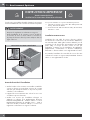
2 - Dimensions et Dispositions pour la Découpe
DIMENSIONS DU PRODUIT
Modèles de cuisinière 30”
29 3/4” (75,8)
35 3/4” (91,0)
35
3/4
”
(9
1,0
)
”
7 3/8” (18,7)
1 3/8” (3,5)
3 3/8” (8,5)
À
27 1/4” ( 69,1)
25 3/4” ( 65,4)
47 3/4” (121,4)
27 1/2” (69,7)
29 3/4” (75,6)
3/8” (1)
Max. 37 1/4” (94,7)
Min. 35 3/8” (89,8)
1" ( 2,5)
3" ( 7,6) [optionnel]
9" (22,8) [optionnel]

FR
4
2 - Dimensions et Dispositions pour la Découpe
DISPOSITIONS POUR LA DÉCOUPE
ÉLECTRIQUE
GAZ
B B
*Position suggérée des
équipements
Bordure minimale de 2 po (5,1)
depuis le mur pour l’alimentation
en gaz ou électrique
3” (7,6)
4” 3/4 (12,3)
A
Min. 18” (45,7)
Min. 30” (76,2)
Jusqu’au bas
de la hotte
Min. 18” (45,7)
Max.
13” (33)
Min. 6”
(15,2)
Min. 6”
(15,2)
C
La totalité de la surface du mur arrière ainsi que la surface se trouvant au-dessus de la table de cuisson doit être faite d’une matière ignifuge.
*Consulter les réglementations locales pour les exigences exactes de localisation.
LARGEUR D’OUVERTURE A & C B
Cuisinière 30 po 30" (76,2) 6” (15,2)
Cuisinière 36 po 36" (91.4) 7” (17.8)
Remarque: La distance par rapport aux matériaux non
combustible doit respecter les réglementations
locales ou, en l’absence de celles-ci, avec le
« National Fuel Gas Code », ANSI Z223.1/
NFPA 54.
Dégagements minimums d’une construction:
Au-dessus de la surface de cuisson [au-dessus de 36 po (91,4 cm)]
• Côtés - 3 po (7,6 cm)
• Avec un dégagement latéral de 3 po (7,6 cm) ou moins,
les placards muraux ne mesurant pas plus de 13 po (33
cm) de profondeur doivent se trouver à 18 po (45,7 cm)
minimum au-dessus de la surface de cuisson.
• Les armoires murales juste au-dessus du produit doivent
se trouver à 30 po (76.2 cm) minimum au-dessus de la
surface de cuisson
• Arrière - 0 po avec dosseret de 3 po (7,6 cm).
ESPACE SUPPLÉMENTAIRES:
Pour une installation en îlot, maintenir une distance minimum
de 6,3 cm (2 ½ po) entre le bord et le dos du comptoir et
7,6 cm (3 po) minimum sur les côtés du comptoir (voir vue
de dessus).
INSTALLATION ÉBARBER
DOS
min 3” (7,6) min 3” (7,6)
min 2 1/2” (6,3)
La page charge ...
La page charge ...
La page charge ...
La page charge ...
La page charge ...
La page charge ...
La page charge ...
La page charge ...
La page charge ...
La page charge ...
La page charge ...
La page charge ...
La page charge ...
La page charge ...
La page charge ...
La page charge ...
La page charge ...
La page charge ...
La page charge ...
La page charge ...
La page charge ...
La page charge ...
La page charge ...
La page charge ...
La page charge ...
La page charge ...
La page charge ...
La page charge ...
-
 1
1
-
 2
2
-
 3
3
-
 4
4
-
 5
5
-
 6
6
-
 7
7
-
 8
8
-
 9
9
-
 10
10
-
 11
11
-
 12
12
-
 13
13
-
 14
14
-
 15
15
-
 16
16
-
 17
17
-
 18
18
-
 19
19
-
 20
20
-
 21
21
-
 22
22
-
 23
23
-
 24
24
-
 25
25
-
 26
26
-
 27
27
-
 28
28
-
 29
29
-
 30
30
-
 31
31
-
 32
32
-
 33
33
-
 34
34
-
 35
35
-
 36
36
-
 37
37
-
 38
38
-
 39
39
-
 40
40
-
 41
41
-
 42
42
-
 43
43
-
 44
44
-
 45
45
-
 46
46
-
 47
47
-
 48
48


Fulgor Milano F6PIR365S1 Guide d'installation
- Catégorie
- Fours
- Taper
- Guide d'installation