Beta 1860BH/200A Mode d'emploi
- Catégorie
- Système de soudage
- Taper
- Mode d'emploi

77612137
MANUALE D’ISTRUZIONEMANUALE D’ISTRUZIONE
ITIT
WELDING INVERTERWELDING INVERTER
INVERTER DI SALDATURAINVERTER DI SALDATURA
INVERTER DE SOLDADURAINVERTER DE SOLDADURA
ONDULEUR DE SOUDAGE ONDULEUR DE SOUDAGE
SCHWEISSINVERTERSCHWEISSINVERTER
INVERSOR DE SOLDAINVERSOR DE SOLDA
СВАРОЧНЫЙ АППАРАТСВАРОЧНЫЙ АППАРАТ
LASAPPARAATLASAPPARAAT
INSTRUCTION MANUALINSTRUCTION MANUAL
ENEN
PLEASE READ THESE INSTRUCTIONS BEFORE INSTALLING, OPERATING, OR SERVICING THIS
PRODUCT. DO NOT DESTROY THIS MANUAL.
LEGGETE LE ISTRUZIONI PRIMA DI INSTALLARE, UTILIZZARE O RIPARARE QUESTO IMPIANTO.
CONSERVATE QUESTO MANUALE.
LEAN LAS INSTRUCCIONES ANTES DE INSTALAR, UTILIZAR O REPARAR ESTOS APARATOS.
CONSERVEN ESTE MANUAL.
LIRE CES INSTRUCTIONS AVANT L’INSTALLATION, L’UTILISATION OU LA REPARATION DE CET
APPAREIL. NE PAS JETER LE PRÉSENT MANUEL.
LESEN SIE DIESE ANLEITUNG VOR DER INSTALLATION, DEM BETRIEB ODER
DER WARTUNG DIESES PRODUKTS. NICHT ZERSTÖREN SIE DIESES HANDBUCH.
LEIA AS INSTRUÇÕES ANTES DE INSTALAR, USAR OU CONSERTAR ESTE EQUIPAMENTO.
CONSERVE ESTE MANUAL.
ПОЖАЛУЙСТА, ВНИМАТЕЛЬНО ПРОЧИТАЙТЕ ДАННУЮ ИНСТРУКЦИЮ ПЕРЕД УСТАНОВКОЙ,
ЭКСПЛУАТАЦИЕЙ И ТЕХНИЧЕСКИМ ОБСЛУЖИВАНИЕМ АППАРАТА. СОХРАНИТЕ ИНСТРУКЦИЮ.
LEES DEZE HANDLEIDING ZORGVULDIG DOOR VOOR U DE MACHINE. DEZE
GEBRUIKSAANWIJZING S.V.P. VOOR GEBRUIK ZORGVULDIG DOORLEZEN.
MANUEL D’INSTRUCTIONSMANUEL D’INSTRUCTIONS
FRFR
MANUAL DE INSTRUCCIONESMANUAL DE INSTRUCCIONES
ESES
MANUAL DE INSTRUÇÕESMANUAL DE INSTRUÇÕES
PTPT
BEDIENUNGSANLEITUNGBEDIENUNGSANLEITUNG
DEDE
ИНСТРУКЦИЯ ПО ЭКСПЛУАТАЦИИИНСТРУКЦИЯ ПО ЭКСПЛУАТАЦИИ
RURU
GEBRUIKSAANWIJZINGGEBRUIKSAANWIJZING
NLNL

2
INDEX
1.0 INTRODUCTION .............................EN-1
1.1 EQUIPMENT IDENTIFICATION EN-1
1.2 RECEIPT OF EQUIPMENT EN-1
2.0 SAFETY WARNING ........................EN-1
2.1 GENERAL INSTRUCTIONS EN-1
2.2 LOCATION EN-1
2.3 SAFETY INSTRUCTIONS EN-3
2.4 FIRE PREVENTION EN-3
2.5 SHIELDING GAS EN-4
2.6 PERMITTED NOISE LEVELS
86/188/EEC RULE. EN-4
2.7 ELECTROMAGNETIC COMPATIBILITY EN-4
2.8 MEDICAL AND FIRST AID TREATMENT EN-4
3.0 BRIEF INTRODUCTION .................EN-5
3.1 TECHNICAL DATA EN-5
4.0 INSTALLATION OF THE
EQUIPMENT .........................................EN-5
5.0 INVERTER FUNCTIONS AND
CONNECTIONS ....................................EN-6
6.0 STICK WELDING ............................ EN-6
7.0 QUALITY OF THE WELD ...............EN-7
8.0 ORDINARY MAINTENANCE ..........EN-7
9.0 POSSIBLE WELDING DEFECTS ..EN-8
10.0 TROUBLESHOOTING ..................EN-8
DECLARATIONS OF CONFORMITY .......... I
TECHNICAL DATA ....................................VI
INDICE
1.0 INTRODUZIONE ...............................IT-1
1.1 TIPO DI GENERATORE DI SALDATURA IT-1
1.2 RICEVIMENTO DELLA SORGENTE DI
SALDATURA IT-1
2.1 ISTRUZIONI GENERALI IT-1
2.2 LUOGO DI UTILIZZO IT-1
2.3 ISTRUZIONI PER LA SICUREZZA IT-3
2.4 PREVENZIONE DI INCENDIO IT-3
2.5 GAS DI PROTEZIONE IT-4
2.6 LIVELLO DI RUMORE PERMESSO
DALLA LEGGE 86/188/EEC IT-4
2.7 COMPATIBILITÀ ELETTROMAGNETICA IT-4
2.8 CURE MEDICHE E DI PRIMO SOCCORSO IT-4
3.0 CARATTERISTICHE GENERALI .....IT-5
3.1 TECHNICAL DATA IT-5
4.0 INSTALLAZIONE
DELL’APPARECCHIATURA ................... IT-5
5.0 FUNZIONI E CONNESSIONI
DELL’INVERTER ....................................IT-6
6.0 SALDATURA AD ARCO ...................IT-6
7.0 QUALITA’ DELLA SALDATURA ......IT-7
8.0 MANUTENZIONE ORDINARIA ........IT-7
9.0 POSSIBILI DIFETTI DI SALDATURA . IT-8
10.0 POSSIBILI INCONVENIENTI DI
FUNZIONAMENTO .................................IT-8
DICHIARAZIONI DI CONFORMITÀ ........... I
DATI TECNICI ........................................... VI
CONTENIDO
1.0 INTRODUCCIÓN .............................ES-1
1.1 TIPO DE GENERADOR DE SOLDADURA ES-1
1.2 RECEPCIÓN DEL EQUIPO DE
SOLDADURA ES-1
2.0 PRECAUCIONES DE SEGURIDAD ES-1
2.1 INSTRUCCIONES GENERALES ES-1
2.2 LUGAR DE UTILIZACIÓN ES-1
2.3 INSTRUCCIONES PARA LA SEGURIDAD ES-3
2.4 PREVENCIÓN ANTINCENDIO ES-3
2.5 GAS DE PROTECCIÓN ES-4
2.6 NIVEL DE RUIDO PERMITIDO POR LA
LEY 86/188/CEE. ES-4
2.7 COMPATIBILIDAD ELECTROMAGNÉTICA ES-4
2.8 ATENCIONES MÉDICAS Y PRIMEROS
AUXILIOS ES-4
3.0 INTRODUCCIÓN .............................ES-5
3.1 DATOS TÉCNICOS ES-5
4.0 INSTALLACIÓN DEL APARATO .... ES-5
5.0 FUNCIONES Y CONEXIONES ...... ES-6
6.0 SOLDADURA POR ARCO .............ES-6
7.0 CALIDAD DE LA SOLDADURA ..... ES-7
8.0 MANUTENCIÓN ORDINARIA ........ES-7
9.0 POSIBLES DEFECTOS DE
SOLDADURA ........................................ES-8
10.0 POSIBLES INCONVENIENTES DE
FUNCIONAMIENTO ..............................ES-8
DECLARACIONES DE CONFORMIDAD ..........
I
DATOS TÉCNICOS ...................................VI
CONTENU
1.0 INTRODUCTION ............................. FR-1
1.1TYPE DE GÉNÉRATEUR DE SOUDAGE FR-1
1.2 RÉCEPTION DE LA SOURCE DE
SOUDAGE FR-1
2.0 PRÉCAUTIONS DE SÉCURITÉ ....FR-1
2.1 RECOMMANDATIONS GÉNÉRALES FR-1
2.2 LIEU D’UTILISATION FR-1
2.3 RECOMMANDATIONS POUR LA
SÉCURITÉ FR-3
2.4 PRÉVENTION D’INCENDIE FR-4
2.5 GAZ DE PROTECTION FR-4
2.6 NIVEAU D’ÉMISSIONS SONORES
AUTORISÉES PAR LA LOI 86/188/EEC FR-4
2.7 COMPATIBILITÉ ÉLECTROMAGNÉTIQUE FR-4
2.8 PREMIERS SOINS DE SECOURS FR-4
3.0 CARACTÉRISTIQUES
GÉNÉRALES .......................................FR-4
3.1 DONNÉES TECHNIQUES FR-5
4.0 INSTALLATION DE L’APPAREIL ... FR-5
5.0 FONCTIONS ET CONNEXIONS
DES ONDULEURS ...............................FR-6
6.0 SOUDAGE À L’ARC ....................... FR-6
7.0 QUALITÉ DE LA SOUDURE .......... FR-7
8.0 MANUTENTION ORDINAIRE .........FR-7
9.0 DÉFAUTS DE SOUDAGE
POSSIBLES .......................................... FR-8
10.0 INCONVÉNIENTS DE SOUDAGE
POSSIBLES .......................................... FR-8
DÉCLARATIONS DE CONFORMITÉ UE ... I
DONNÉES TECHNIQUES ........................VI

3
INHALT
1.0 EINFÜHRUNG ................................... D-1
1.1 IDENTIFIKATION DES EQUIPMENTS D-1
1.2 ERHALT DES EQUIPMENTS D-1
2.0 SICHERHEITSWARNUNG ............... D-1
2.1 ALLGEMEINE ANWEISUNGEN D-1
2.2 STANDORT D-1
2.3 SICHERHEITSANWEISUNGEN D-3
2.4 BRANDSCHUTZ D-3
2.5 SCHUTZGAS D-4
2.6 ZULÄSSIGE LÄRMPEGEL 86/188/EEC-
REGEL. D-4
2.7 ELEKTROMAGNETISCHE
KOMPATIBILITÄT. D-4
2.8 MEDIZINISCHE BEHANDLUNG UND
NOTFALLBEHANDLUNG D-4
3.0 KURZE EINFÜHRUNG ..................... D-5
3.1 TECHNISCHE DATEN .................................D-5
4.0 INSTALLATION DES EQUIPMENTS D-5
5.0 INVERTERFUNKTIONEN UND
ANSCHLÜSSE ........................................ D-6
6.0 STICK-SCHWEISSEN ...................... D-6
7.0 QUALITÄT DER SCHWEISSNAHT .. D-7
8.0 GEWÖHNLICHE WARTUNG ............ D-7
9.0 MÖGLICHE SCHWEISSFEHLER ..... D-8
10.0 FEHLERBEHEBUNG...................... D-8
KONFORMITÄTSERKLÄRUNGEN ............ I
TECHNISCHE DATEN ...............................VI
ÍNDICE
1.0 INTRODUÇÃO ................................ PT-1
1.1 TIPO DE GERADOR DE SOLDA PT-1
1.2 RECEBIMENTO DA SOLDADEIRA PT-1
2.0 PRECAUÇÕES DE SEGURANÇA PT-1
2.1 INSTRUÇÕES GERAIS PT-1
2.2 LUGAR DE UTILIZAÇÃO PT-1
2.3 INSTRUÇÕES PARA A SEGURANÇA PT-3
2.4 PREVENÇÃO DE INCÊNDIOS PT-3
2.5 GÁS DE PROTEÇÃO PT-4
2.6 NÍVEL DE RUÍDO PERMITIDO PELA
LEI 86/188/EEC PT-4
2.7 COMPATIBILIDADE ELETROMAGNÉTICA PT-4
2.8 CUIDADOS MÉDICOS E DE PRIMEIROS-
SOCORROS. PT-4
3.0 CARACTERÍSTICAS GERAIS ....... PT-5
3.1 DADOS TÉCNICOS PT-5
4.0 INSTALAÇÃO DO EQUIPAMENTO PT-5
5.0 CONEXÕES E FUNÇÕES DO
INVERSOR ............................................ PT-6
6.0 SOLDA A ARCO ............................. PT-6
7.0 QUALIDADE DA SOLDA ................ PT-7
8.0 MANUTENÇÃO ORDINÁRIA ......... PT-7
8.0 POSSÍVEIS DEFEITOS DE SOLDA . PT-8
10.0 POSSÍVEIS INCONVENIENTES
DE FUNCIONAMENTO ......................... PT-8
DECLARAÇÕES DE CONFORMIDADE .... I
DADOS TÉCNICOS ..................................VI
ИНДЕКС
1.0 ВВЕДЕНИЕ ....................................RU-1
1.1 ИДЕНТИФИКАЦИЯ ОБОРУДОВАНИЯ RU-1
1.2 ПРИЕМ ОБОРУДОВАНИЯ RU-1
2. МЕРЫ БЕЗОПАСНОСТИ ................RU-1
2.1 ОБЩИЕ ПОЛОЖЕНИЯ RU-1
2.2 РАЗМЕЩЕНИЕ RU-1
2.3 ИНСТРУКЦИИ ПО БЕЗОПАСНОСТИ. RU-3
2.4 ПРЕДОТВРАЩЕНИЕ ПОЖАРА. RU-4
2.5 ЗАЩИТНЫЙ ГАЗ. RU-4
2.6 ДОПУСТИМЫЙ УРОВЕНЬ ШУМА ПО
НОРМАМ 86/188/ПОЛОЖЕНИЕ ЕЭС RU-4
2.7 ЭЛЕКТРОМАГНИТНАЯ
СОВМЕСТИМОСТЬ. RU-4
2.8 ОКАЗАНИЕ ПЕРВОЙ ПОМОЩИ RU-5
3.0 КРАТКАЯ ИНФОРМАЦИЯ ............RU-5
3.1 ТЕХНИЧЕСКИЕ ХАРАКТЕРИСТИКИ RU-5
4.0 УСТАНОВКА ОБОРУДОВАНИЯ ...RU-6
5.0 ПОДСОЕДИНЕНИЕ И ФУНКЦИИ
ИНВЕРТЕРА .........................................RU-7
6.0 ЭЛЕКТРОДНАЯ СВАРКА .............RU-7
7.0 КАЧЕСТВО СВАРКИ .....................RU-8
8.0 ТЕХНИЧЕСКОЕ ОБСЛУЖИВАНИЕ .RU-8
9.0 ВОЗМОЖНЫЕ ДЕФЕКТЫ ПРИ
СВАРКЕ ................................................RU-9
10.0 УСТРАНЕНИЕ НЕИСПРАВНОСТЕЙ
...............................................................RU-9
ДЕКЛАРАЦИИ СООТВЕТСТВИЯ ............. I
ТЕХНИЧЕСКИЕ ХАРАКТЕРИСТИКИ ..... VI
INDEX
1.0 INLEIDING ......................................NL-1
1.1 SOORT LASGENERATOR NL-1
1.2 DE LASBRON ONTVANGEN NL-1
2.0 VEILIGHEIDSWAARSCHUWINGEN NL-1
2.1 PERSOONLIJKE BESCHERMING NL-1
2.2 LICHT NL-1
2.3 WERKGEBIED NL-2
2.4 ELEKTRISCHE INSTALLATIE NL-3
2.5 BRANDPREVENTIE NL-4
2.6 BESCHERMEND GAS NL-4
2.7 GELUID NL-5
2.8 E.H.B.O. NL-5
3.0 ALGEMENE EIGENSCHAPPEN ....NL-5
3.1 TECHNISCHE GEGEVENS NL-5
4.0 DE GENERATOR INSTALLEREN .. NL-6
5.0 FUNCTIES EN AANSLUITINGEN VAN
DE INVERTER ......................................NL-6
6.0 BOOGLASSEN ............................... NL-7
7.0 LASKWALITEIT .............................. NL-7
8.0 NORMAAL ONDERHOUD ..............NL-8
9.0 MOGELIJKE DEFECTEN TIJDENS
HET LASSEN ........................................NL-9
10.0 MOGELIJKE STORINGEN TIJDENS
DE FUNCTIONERING ...........................NL-9
VERKLARINGEN VAN
OVEREENSTEMMING ............................... I
TECHNISCHE GEGEVENS ...................... VI

4

EN-1
- an adequate maintenance of the equipment.
Therefore, be sure this manual is carefully
read and understood by the maintenance
and technical operators.
2.2 LOCATION
Welding processes of any kind can be dange-
rous not only to the operator but to any person
situated near the equipment if safety and opera-
ting rules are not strictly observed.
Therefore the owner and the operator must
be aware of all possible risks so that they
may take the necessary safety precautions to
avoid any kind of accident at work.
The main precautions to be observed are:
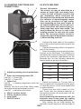
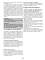
- Operators should protect their body by
wearing non ammable, close tting protec-
tive clothing, without
pockets or turned-up
trousers. Oil or grea-
se should be carefully
removed from all arti-
cles, before wearing.
Operators should also
wear closed safety bo-
ots with steel toe caps
and with rubber soles
( Fig. 1).
1. Leather gloves
2. Leather aprons
3. Shoes Cover
4. Security shoes
5. Face mask
6. Crust leather slee-
ves to protect the
arms.
According to the requirements
in 2006/25/EC Directive and EN
12198 Standard, the equipment
is a category 2. It makes compul-
sory the adoption of Personal Protective
Equipment (PPE) having lter with a pro-
tection degree up to a maximum of 15, as
required by EN169 Standard.
- Operators should wear a non- ammable
welding helmet or face shield designed so as
to shield the neck and the face, also on the
sides. The helmet or the face shield should
be tted with protective glasses adequate to
the welding process and current used. Glass
screens must always be kept clean, and im-
mediately replaced if they are broken or cra-
cked (Fig.2). It is good practice to install a
IMPORTANT
CAREFULLY READ THE FOLLOWING IN-
STRUCTIONS BEFORE INSTALLING THE
UNIT AND MAKE SURE THAT THE YEL-
LOW AND GREEN GROUNDING CON-
DUCTOR IS DIRECTLY CONNECTED TO
THE GROUND IN THE WELDING LOCA-
TION.
THE UNIT MUST NEVER BE OPERATED
WITHOUT PANELS AS THIS COULD BE
DANGEROUS FOR THE OPERATOR AND
COULD CAUSE SERIOUS DAMAGE TO
THE EQUIPMENT.
THE UNIT WORKS ONLY WITH INPUT
VOLTAGE OF 230Vac -50 Hz-1Ph.
THE INPUT CABLE IS ENERGIZED EVEN
WHEN THE MAIN SWITCH IS ON THE “0”
POSITION. THEREFORE, BEFORE SER-
VICING THE EQUIPMENT, MAKE SURE
THAT THE 2 POLE PLUG IS DISCON-
NECTED FROM THE LINE SOCKET.
1.0 INTRODUCTION
1.1 EQUIPMENT IDENTIFICATION
The unit’s identication number (specication
or part number) model, and serial number
usually appear on a nameplate attached to the
rear panel. Equipment which does not have a
control panel such as gun and cable assem-
blies is identied only by the specication or
part number printed on the shipping container.
Record these numbers for future reference.
1.2 RECEIPT OF EQUIPMENT
When you receive the equipment, compare
it with the invoice to make sure it is complete
and inspect the equipment for possible dama-
ge due to shipping. All machines dispatched
have been scrupulously checked. However,
should your machine not work properly, con-
sult the section on TROUBLE SHOOTING in
this manual. If the fault persists, consult your
authorized dealer.
2.0 SAFETY WARNING
2.1 GENERAL INSTRUCTIONS
This manual contains all the necessary in-
structions for:
- the installation of the equipment;
- a correct operating procedure;
Optical Radiation Emission
Category 2
(EN 12198)

EN-2
pane of transparent glass on top of the adiac-
tinic glass, between it and the welding area.
This pane can be frequently replaced when
incandescent spatters and deposits greatly
reduce visibility. When working with coated
plates that emit toxic fumes when heated,
use an air-supplied respirator.
- Welding should be done in a closed area
that does not open onto other working areas,
in order to protect all workers against radia-
tion and fumes. If such an area cannot be
provided, the welding area must be delimi-
ted by protective screens painted in opaque
black large enough to restrain the visibility of
any person situated near the area (Fig. 3).
- Remove all chlorinated solvents from the
welding area before welding. Certain chlori-
nated solvents decompose when exposed to
ultraviolet radiation to form phosgene gas.
- Never, under any circumstances, look at
an electric arc without suitable eye protection
(Fig. 4).
- Always wear protective goggles with tran-
sparent lenses to prevent splinters or other fo-
reign particles from harming the eyes (Fig. 5).
- Adequate local exhaust ventilation must
be used in the area. It should be provided
through a mobile hood or through a built-in sy-
stem on the workbench that provides exhaust
ventilation from the sides, the front and below,
but not from above the bench so as to avoid
raising dust and fumes. Local exhaust ventila-
tion must be provided together with adequate
general ventilation and air circulation, particu-
larly when work is done in a conned space.
(Fig.6). Any symptom of stain or soreness to
the eyes, the nose or the throat may be cause
by inadequate ventilation; work must be stop-
ped immediately and all necessary steps must
be taken to provide adequate ventilation.
- Welding process must be performed on
metal coatings thoroughly cleaned from la-
yers of rust or paint, to avoid production of
harmful fumes. The parts degreased with a
solvent must be dried before welding.
- Do not weld metal or painted metal contai-
ning zinc, lead, cadmium or beryllium unless
the operator, or anyone else subjected to the
fumes, is wearing respiratory equipment or
an air-supplied helmet.
Fig.2
Fig.3
Fig.4
Fig.6
Fig.5

EN-3
- The employer is required to evaluate the
risks to which workers are exposed during the
use of welding machines, focusing in particu-
lar on the risks deriving from the welding of
stainless steel alloys. In relation to the legisla-
tion in force in the country where the welding
machines are sold, the employer who uses
the welding machines to weld stainless steel
alloys is required to evaluate the carcinogenic
risk deriving from the development of welding
fumes containing nickel and hexavalent chro-
mium in gaseous form (remember that nickel
and hexavalent chromium in the gaseous state
are carcinogenic).
2.3 SAFETY INSTRUCTIONS
For your safety, before connecting the source
to the line, closely follow these instructions:
- an adequate two-pole switch must be in-
serted before the two-pole main outlet; this
switch must be equipped with time-delay fu-
ses and it must match the data specied in
the chapter “Technical Specication”;
- the mono-phase connection with ground
must be made with a two-pole plug compati-
ble with the above mentioned socket;
- two wires of the two-pole input cable are
used for the connection with the mono-phase
line and the yellow-green wire for the compul-
sory connection to the ground in the welding
location;
- connect all the metal parts which are near
the operator in the welding location by using
cables bigger or of the same cross section of
the welding cable to a ground terminal;
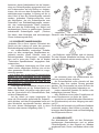
- when working in a conned space, the po-
wer source must be kept outside the welding
area and the ground cable should be welded
to the workpiece; do not work in a damp or
wet area in these conditions (Fig. 7).
- do not use damaged welding or input ca-
bles (Fig. 8);
- the operator should never touch, with any
part of his body, high temperature or electri-
cally hot metal parts (Fig. 9);
- the operator should never wind the wel-
ding cables around his body;
- the welding gun should never be pointed
at the operator or at another person. The po-
wer source has a protection level IP 22; the-
refore, it prevents:
- any manual contact with hot or moving in-
ternal parts;
- the insertion of any solid body with more
than 12mm diameter;
- protected against vertically falling drops
of water (condensation) with inclination max
of 15°.
The source must never be operated wi-
thout its panels; this could cause serious
injury to the operator and could damage the
equipment itself.
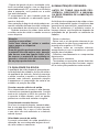
2.4 FIRE PREVENTION
The working area should conform to the Sa-
fety Regulations, and therefore, re extin-
guishers should be provided in the area
and walls, ceiling and oor should be non-
ammable. All combustible material must
be moved from the welding area (Fig. 10). If
combustibles cannot be moved, they must be
protected with re-resistant cover. Ventilate
potentially ammable atmospheres before
welding. Never operate in an atmosphere
which contains heavy concentrations of dust,
ammable gas or combustible liquid vapor.
The power source must be located in a safe
area with a rm and at oor; it should not be
put against a wall. Do not weld containers in
which fuel, lubricant or any other ammable
material have been stored. After having com-
Fig.7
Fig.8
Fig.9

EN-4
pleted your work, always check that the area
is free of glowing or smoldering material.
2.5 SHIELDING GAS
Use the correct shielding gas for the welding
process. Be sure that the regulator/owmeter
mounted on the cylinder is working well.
Remember to keep away the cylinder from
any source of heat.
2.6 PERMITTED NOISE LEVELS 86/188/
EEC RULE.
Under normal circumstances the equipment
used for electric arc welding does not exceed
the permitted 80 dBA. However in certain
conditions eg. high welding parameters in
conned spaces, noise levels may exceed
the permitted level. For this reason it is stron-
gly recommended that operatives wear ap-
propriate ear protection.
2.7 ELECTROMAGNETIC
COMPATIBILITY.
Before installing the STICK/TIG welding unit,
carry out an inspection of the surrounding
area, observing the following guidelines:
1- Make sure that there are no other power
supply cables, control lines, telephone leads
or other equipment near the unit.
2- Make sure that there are no radio recei-
vers or television appliances.
3- Make sure there are no computers or other
control systems.
4- Make sure that there is no-one with a pa-
cemaker or hearing aid in the area around
the unit.5- Check the immunity of any other
equipment operating in the same envi-
ronment.
In certain cases additional protective measu-
res may be required.
Interference can be reduced in the following
ways:
1- If there is interference in the power sup-
ply line, an E.M.C. lter should be inserted
between the mains and the unit.
2- The output cables of the unit should be
shortened; these should be kept close toge-
ther and stretched along the ground.
3- All the panels of the unit should be cor-
rectly closed after carrying out maintenance.
2.8 MEDICAL AND FIRST AID
TREATMENT
First aid facilities and a qualied rst aid per-
son should be available for each shift for im-
mediate treatment of electrical shock victims.
A medical facility should be close by for im-
mediate treatment of ash burns of the eye
and skin burns.
EMERGENCY FIRST AID:
Call physician and ambulance immedia-
tely.
Use First Aid techniques recommended
by The Red Cross.
DANGER: ELECTRIC SHOCK CAN BE
FATAL
If person is unconscious and electric
shock is suspected , do not touch the
person if he or she is in contact with wel-
ding equipment, or other live electrical
parts. Disconnect (open) power at wall
switch and then use First Aid. Dry wood,
wooden broom, or other insulating ma-
terial can be used to move cables, if ne-
cessary, away from the person.
Fig.10

EN-5
3.0 BRIEF INTRODUCTION
Your welder belongs to a range of welding in-
verters for MMA - Manual Metal Arc Welding
that adopts the latest pulse width modulation
(PWM) technology and the insulated gate
bipolar transistor (IGBT) power module to
grant optimal performances: constant current
output to make welding arc more stable and
stepless current regulation.
3.1 TECHNICAL DATA
You may nd the data table of your machi-
ne in the last page of this manual.
The data may also vary according to the
torch that is gonna be used with the ge-
nerator.
4.0 INSTALLATION OF THE
EQUIPMENT
Proper operation of the generator is ensu-
red by adequate installation. The assem-
bly of the inverter must be done by expert
people, following the instructions and in
full respect of the safety standards.
- Remove the welder from the carton box.
BEFORE ATTEMPTING ANY ELECTRI-
CAL CONNECTION CHECK THE DATA
PLATE AND MAKE SURE THAT THE IN-
PUT VOLTAGE AND THE FREQUENCY
ARE THE SAME OF THE MAINS OUTLET
TO BE USED.
EARTHING
- To protect users the welding machi-
nes must be connected properly to the
earth (ground) system (INTERNATIONAL
SAFETY REGULATIONS).
- It is indispensable to earth (ground)
the machine properly with the yellow-
green conductor of the power supply ca-
ble, in order to avoid discharges due to
accidental contacts with earthed objects.
- The chassis (that is conductive) is
electrically connected to the earth con-
ductor. Failure to earth the equipment
correctly can cause electric shocks dan-
gerous to the users.
- Plug the inverter to the mains.
Do not use the generator with input ca-
bles’ extensions longer than 10m and
thinner than 2.5mm². Remember to keep
them layed and not wound or entangled.
Do not use the welder with the side panels
partially or completely removed in order
to avoid accidental contacts with inner
live parts.
- The inverter is now ready for use. Make
sure you are welding in a properly ventilated
area and that the ventilation openings of the
machine are not obstructed (poor air ventila-
tion may reduce the duty cycle of the unit and
cause damages). Now you may choose the
welding process by connecting the accesso-
ries as showed in the following pages.

EN-6
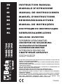
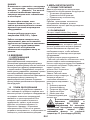
5.0 INVERTER FUNCTIONS AND
CONNECTIONS
1 Adjusting welding current potentiome-
ter
2 Green Led indicating power ON
Led ON = Power ON
Led OFF = Power OFF
3 Yellow Led
Led ON = indicating temperature limits are
exceeded.
Warning: Let unit to cool down. When ready,
the orange led will automatically shut off.
Led ON = indicating short circuit.
4 25mm² positive socket
5 25mm² negative socket
6 Input Cable
7 ON/OFF Switch
6.0 STICK WELDING
General information
The electric arc may be described as a
source of bright light and strong heat;
in fact, the ow of electric current in the
gas atmosphere which surrounds the
electrode and the workpiece determines
the radiation of electromagnetic waves
that can be perceived as light and/or
heat depending on their wave length. At
an unperceivable level, the arc also pro-
duces ultra-violet and infra-red light; io-
nizing rays have never been noted. The
heat produced by the arc is used in the
welding process to melt and join metal
parts. The necessary electric current is
supplied by special equipment common-
ly called welding machine.
- Connect the earth cable to the negative
pole of the Inverter and the earth clamp to the
workpiece.
- Connect the welding cable to the positive
pole of the Inverter.
- Select the welding current using the poten-
tiometer on the front panel. The welding cur-
rent should be chosen following the instruction
given by the electrodes manufacturer on the
electrode box, but the following indications
may be useful as general information:
- Switch the Inverter on. The two leds on
the front panel will be respectively the green
= lit and the yellow = off (for more details refer
to section before).
- Protect your face with a mask or a hel-
met. Touch, with the electrode fastened, in
the electrode holder, the work piece until the
arc will be struck.
Avoid hammering the workpiece with the
electrode since it may loose the coating
and increase the arc striking difculties.
- After striking the arc keep feeding the
electrode into the weld pool with an angle of
RETEMAIDEDORTCELETNERRUCGNIDLEW
mm5.1A04-A03
mm0.2A56-A05
mm5.2A001-A07
mm52.3A041-A001
mm0.4A061-A041
3
2
4
5
1
7
6

EN-7
about 60° and moving left to right so that you
may control visually the welding. The length
of the arc can also be controlled by lifting or
lowering slightly the electrode. Also a varia-
tion of the welding angle may increase the
size of the weld pool improving the capacity
of surfacing of the slag.
- At the end of the weld let the slag cool off
before removing it, using the brush-hammer.
CAUTION:
Protect your eyes when hitting the slag
with the chip hammer to avoid damages.
CAUTION:
A bad start can be due to the dirty
workpiece, a bad connection between
earth cable and work piece, or the bad
fastening of the electrode in the electro-
de holder.
7.0 QUALITY OF THE WELD
The quality of the weld will depend mainly on
the ability of the welder, on the type of weld
and on the quality of the electrode: Choose
the proper electrode before attempting to
weld, paying attention to the thickness and
composition of the metal to be welded.
Correct welding current.
If the current is too high the electrode will burn
fast and the weld pool will be wide irregular
and difcult to be controlled. If the current is
too low you will lack power and the weld pool
will be narrow and irregular.
Correct arc length.
If the arc is too long it will cause spatters and
small fusion of the welding piece. If the arc is
too short the arc heat will be insufcient cau-
sing the electrode to stick to the workpiece.
Correct welding speed.
The correct welding speed will consent to
achieve a weld of proper width, without wa-
ves or craters.
8.0 ORDINARY MAINTENANCE
CAUTION!!!
BEFORE CARRY OUT ANY MAINTENAN-
CE, UNPLUG THE MACHINE FROM THE
MAINS POWER SUPPLY.
The efciency of the welding system over
time is directly related to the frequency of
maintenance jobs, such as:
For welding machines only need to be taken
care inside. The dustier the working environ-
ment is, the more often this should be done.
- Take off the lid.
- Remove all traces of dust in the inner
parts of the generator with a jet of compres-
sed air at a pressure under 3Kg/cm.
- Check all electrical connections, making
sure that nuts and screws have been rmly
tightened.
- Do not delay in replacing worn-out parts.
- Put the lid back on.
- After completing the above operations,
the generator is ready to be restarted fol-
lowing the instructions given in this manual.

EN-8
9.0 POSSIBLE WELDING DEFECTS
DEFECT CAUSES SUGGESTIONS
POROSITY Acid electrode on steel with high
sulphur content.
Electrode oscillates too much.
Workpieces are too far apart.
Workpiece being welded is cold.
Use basic electrodes.
Move edges to be welded closer
together.
Move slowly at the beginning.
Lower welding current.
CRACKS Material to be welded is dirty (e.g.
oil, paints, rust, oxides).
Not enough current.
Cleaning workpieces before
welding is an essetial method of
achieving neat weld beads.
LIMITED
PENETRATION
Low current.
High welding rate.
Reversed polarity.
Electrode inclined in position
opposite to its movement.
Make sure operating parameters
are regulated and improve prepa-
ration of workpieces.
HIGH SPRAYS Electrode is too inclined. Make appropriate corrections.
PROFILE DEFECTS Welding parameters are incorrect.
Pass rate is not related to opera-
ting parameters requirements.
Follow basic and general welding
principles.
ARC INSTABILITY Not enough current. Check condition of electrode and
earth wire connection.
ELECTRODE MELTS
OBLIQUELY
Electrode core is not centered.
Magnetic blow phenomenon.
Replace electrode.
Connect two earth wires to opposi-
te sides of the workpiece.
INCONVENIENCE CAUSE REMEDY
SPARK WILL NOT
START
Bad primary connection.
Inverter PCB is defective.
Check primary connection.
Contact after sales service centre.
NO OUTPUT
VOLTAGE
Overheated unit, yellow LED lit
Internal relay has failed.
Inverter PCB is defective.
Wait for thermal cutout to be reset.
Check power line. Reset the unit
by turning it off and on after 20
seconds.
Contact after sales service centre.
Contact after sales service centre.
WRONG OUTPUT
CURRENT
Defective control potentiometer.
Low primary power supply
voltage.
Contact after sales service centre.
Check power line.
10.0 TROUBLE SHOOTING

IT-1
IMPORTANTE
LEGGETE ATTENTAMENTE LE ISTRUZIONI
PRIMA DI INSTALLARE L’APPARECCHIO
E ACCERTATEVI CHE IL CONDUTTORE
DI MESSA A TERRA GIALLO E VERDE
SIA DIRETTAMENTE COLLEGATO ALLA
TERRA NEL LUOGO DI SALDATURA.
L’APPARECCHIO NON DEVE MAI
ESSERE UTILIZZATO SENZA I PANNELLI,
IN QUANTO CIO’ POTREBBE ESSERE
PERICOLOSO PER L’OPERATORE E
POTREBBE CAUSARE GRAVI DANNI
ALL’ATTREZZATURA .
L’UNITA’ LAVORA SOLO CON UNA
TENSIONE DI ALIMENTAZIONE DI 230Vac-
50Hz-1Ph.
IL CAVO DI ALIMENTAZIONE HA
UNA TENSIONE ANCHE QUANDO
L’INTERRUTTORE PRINCIPALE É SULLA
POSIZIONE “0”. QUINDI PRIMA DI RIPARARE
L’APPARECCHIO ASSICURATEVI CHE LA
SPINA A DUE POLI NON SIA COLLEGATA
ALLA PRESA DI CORRENTE.
1.0 INTRODUZIONE
1.1 TIPO DI GENERATORE DI
SALDATURA
Il dati identicativi del generatore e il suo nu-
mero di serie compaiono sempre sulla targa
dati sul pannello posteriore. Le torce e i cavi
sono identicati dalle speciche o dal numero
di serie stampati sul loro imballo. Prendete nota
di questi numeri per un eventuale riferimento.
1.2 RICEVIMENTO DELLA SORGENTE
DI SALDATURA
Quando ricevete l’apparecchiatura confrontatela
con la fattura per assicurarvi che ci sia corrispon-
denza e controllatela bene al ne di individuare
possibili danni dovuti al trasporto. Tutte le appa-
recchiature spedite sono state sottoposte ad un
rigoroso controllo di qualità. Se tuttavia la Vostra
apparecchiatuta non dovesse funzionare corret-
tamente, consultate la sezione RICERCA GUA-
STI di questo manuale. Se il difetto permane,
consultate il Vostro concessionario autorizzato.
2.0 PRECAUZIONI SULLA SICUREZZA
2.1 ISTRUZIONI GENERALI
Questo manuale contiene tutte le istruzioni
necessarie per :
- l’installazione della sorgente di saldatura;
- un corretto utilizzo;
- un’adeguata manutenzione.
Assicuratevi che questo manuale venga letto
e capito sia dall’operatore che dal personale
tecnico addetto alla manutenzione.
2.2 LUOGO DI UTILIZZO
Se le norme di sicurezza e di utilizzo non
vengono osservate attentamente, le opera-
zioni di saldatura possono risultare perico-
lose non solo per l’operatore, ma anche per
le persone che si trovano nelle vicinanze del
luogo di saldatura.
Percio’ il proprietario e l’utilizzatore devono
essere a conoscenza di tutti i rischi possibili,
in modo tale da poter prendere le precauzioni
necessarie per evitare incidenti sul lavoro.
Le precauzioni principali da osservare sono:
- Gli operatori devono proteggere il proprio
corpo indossando tute di protezione chiuse
e non inammabili, senza tasche o risvolti.
Eventuali tracce di olio
o grasso devono es-
sere rimosse da tutti
gli indumenti prima di
indossarli. Gli opera-
tori devono anche cal-
zare stivali con punta-
le di acciaio e suole di
gomma ( Fig. 1).
1. Guanti in pelle
2. Grembiule in pelle
3. Copriscarpe
4. Scarpe di
sicurezza
5. Mashera
6.Maniche in cuoio di
crosta a protezione
delle braccia.
Conformemente a quanto pre-
scritto nella Direttiva 2006/25/
CE e alla norma EN 12198, l’ap-
parecchiatura è di categoria 2. Si rende
obbligatoria l’adozione di Dispositivi di
Protezione Individuale (DPI) con grado
di protezione del ltro no ad un mas-
simo di 15, secondo quanto prescritto
dalla Norma EN169.
- Gli operatori devono indossare un casco
o una maschera per saldatore, non inam-
mabile, disegnato in modo da proteggere il
collo e il viso, anche dai lati. L’elmetto o la
Optical Radiation Emission
Category 2
(EN 12198)

IT-2
- Indossate sempre occhiali di protezione
con lenti trasparenti per evitare schegge ed
altre particelle estranee che possono dan-
neggiare gli occhi (Fig.5).
- L’area di saldatura deve essere fornita di
un’ adeguata aspirazione locale che può es-
sere data da una cappa di aspirazione o da
un sistema precostruito sul banco di lavoro
che provveda all’aspirazione dai lati, davanti
e sotto, ma non sopra al banco così da evi-
tare il formarsi di polvere e fumi. L’apirazione
locale deve essere abbinata ad una adegua-
ta ventilazione generale ed al ricircolo d’aria
specialmente quando si sta lavorando un uno
spazio ristretto (Fig.6). Qualsiasi sintomo di
fastidio o dolore agli occhi, al naso o alla gola
può essere causato da una inadeguata ven-
tilazione; in tal caso interrompete immedia-
tamente il lavoro e provvedete all’adeguata
ventilazione dell’area.
maschera devono essere dotati di vetri pro-
tettivi scuri adatti al processo di saldatura e
alla corrente usata. Occorre mantenere sem-
pre puliti i vetri di protezione e sostituirli se
sono rotti o crepati (Fig.2). E’ buona abitudi-
ne installare un vetro trasparente tra il vetro
inattinico e l’area di saldatura. Questo vetro
deve essere sostituito con frequenza quan-
do spruzzi e schegge riducono notevolmente
la visibilità. Utilizzate un respiratore quando
lavorate con piastre rivestite, che emettono
fumi tossici se riscaldate.
- L’operazione di saldatura deve essere
eseguita in un ambiente isolato rispetto alle
altre zone di lavoro, così da proteggere gli
operatori contro radiazioni e fumi. Se ciò non
è possibile, l’area di saldatura deve essere
delimitata con pannelli di protezione color
nero larghi abbastanza da restringere il cam-
po visivo delle persone nelle vicinanze della
zona (Fig.3).
- Prima di saldare allontanate dal luogo di
lavoro tutti i solventi che contengono cloro.
Alcuni solventi clorinati si decompongono
una volta esposti a radiazioni ultraviolette,
formando così gas fosgene.
- Non guardate mai, per nessun motivo, un
arco voltaico senza una adatta protezione
agli occhi ( Fig.4 ).
Fig.2
Fig.3
Fig.4
Fig.5
Fig.6

IT-3
- non utilizzate cavi di alimentazione o di
saldatura danneggiati (Fig.8);
- l’operatore non deve mai toccare, con
nessuna parte del corpo, pezzi di metallo ri-
scaldati ad alta temperatura o carichi elettri-
camente (Fig.9);
- l’operatore non deve mai avvolgere i cavi
di saldatura attorno al proprio corpo;
- la torcia di saldatura non deve mai essere
puntata verso l’operatore o un’altra persona.
L’apparecchio ha una protezione in classe IP
22, quindi impedisce:
- ogni contatto manuale con parti inter-
ne calde o in movimento;
- l’inserimento di corpi solidi con un dia-
metro superiore a 12mm;
- una protezione contro le cadute verti-
cali di acqua (condensazione) con inclinazio-
ne massima di 15°.
Il generatore non deve mai essere utilizzato
senza i suoi pannelli; ciò potrebbe causare
gravi lesioni all’operatore oltre a danni alla
apparecchiatura stessa.
2.4 PREVENZIONE DI INCENDIO
L’ area di lavoro deve essere conforme alle
norme di sicurezza, quindi occorre siano pre-
senti gli estintori. Mentre il softto, il pavimen-
to e le pareti devono essere non inammabili.
- Il procedimento di saldatura deve esse-
re eseguito su superci metalliche ripulite
da strati di ruggine o vernice e ciò al ne di
evitare il formarsi di fumi dannosi. Prima di
saldare occorre asciugare le parti che sono
state sgrassate con solventi.
- Non saldate metalli o metalli verniciati
che contengono zinco, piombo, cadmio o be-
rillio a meno che l’operatore e le persone vici-
ne non indossino un respiratore o un elmetto
con bombola di ossigeno.
- Il datore di lavoro è tenuto valutare i rischi
a cui sono esposti i lavoratori durante l’impie-
go delle saldatrici, soffermandosi in particolar
modo sui rischi derivanti dalla saldatura delle
leghe in acciaio inox. In relazione alla legi-
slazione vigente nel paese in cui le saldatrici
vengono commercializzate, il datore di lavo-
ro che impiega le saldatrici per effettuare la
saldatura di leghe in acciaio inox è tenuto a
valutare il rischio cancerogeno derivante dal-
lo svilupparsi dei fumi di saldatura contenenti
nichel e cromo esavalente in forma gassosa
(si ricorda che il Nichel e il Cromo esavalente
nello stato gassoso sono cancerogeni).
2.3 ISTRUZIONI PER LA SICUREZZA
Per salvaguardare la vostra sicurezza, se-
guite attentamente queste istruzioni prima di
collegare il generatore alla linea:
- un interruttore adeguato a due poli deve
essere inserito prima della presa principale di
corrente; questa deve essere dotata di fusibili
ritardati che devono essere conformi ai valori
indicati nel capitolo “Dati Tecnici”;
- il collegamento mono-fase con cavo di terra
deve essere eseguito con una spina a due poli
compatibile con la presa menzionata sopra;
- i due li del cavo di alimentazione a due
poli sono impiegati per il collegamento con la
linea mono-fase mentre il lo giallo-verde è
usato per il collegamento obbligatorio a terra
nel luogo di saldatura;
- collegate al terminale di terra tutte le parti
metalliche che sono vicine all’operatore, uti-
lizzando cavi più grossi o della stessa sezio-
ne dei cavi di saldatura;
- quando state lavorando in un luogo ri-
stretto, l’apparecchio deve essere collocato
fuori dell’area di saldatura e il cavo di massa
deve essere ssato al pezzo in lavorazione.
Non operate in una zona umida o bagnata in
queste condizioni (Fig.7);
Fig.7
Fig.8
Fig.9

IT-4
Tutto il materiale combustibile deve essere
spostato dal luogo di lavoro (Fig.10). Se non
si può allontanare il combustibile, copritelo
con una copertura resistente al fuoco. Prima
di cominciare a saldare, ventilate gli ambien-
ti dove l’area è potenzialmente inammabi-
le. Non operate in un’atmosfera che ha una
concentrazione notevole di polvere, gas in-
ammabile o vapore liquido combustibile. Il
generatore deve essere situato in un luogo
con pavimento solido e liscio; non deve esse-
re appoggiato al muro. Non saldate recipienti
che contenevano benzina, lubricante o al-
tre sostanze inammabili. Dopo aver nito di
saldare, accertatevi sempre che nella zona
non siano rimasti materiali incandescenti o in
amme.
2.5 GAS DI PROTEZIONE
Per il processo di saldatura utilizzate il gas
corretto. Assicuratevi che il regolatore instal-
lato sulla bombola funzioni correttamente.
Ricordate di conservare la bombola lontano
da fonti di calore.
2.6 LIVELLO DI RUMORE PERMESSO
DALLA LEGGE 86/188/EEC
Operando in condizioni normali, l’apparecchiatu-
ra utilizzata per la saldatura ad arco non supera
gli 80 dBA. Comunque in condizioni particolari,
ad esempio alti parametri di saldatura in ambien-
ti limitati, i livelli del rumore possono eccedere il
limite permesso. Per questa ragione è fortemen-
te raccomandato di indossare idonee protezioni
per le orecchie.
2.7 COMPATIBILITÀ
ELETTROMAGNETICA
Prima di installare una unità di saldatura
STICK/TIG, effettuate una ispezione dell’a-
rea circostante, osservando quanto segue:
1- Accertatevi che vicino all’ unità non vi si-
ano altri cavi di generatori, linee di controllo,
cavi telefonici o apparecchiature varie.
2- Controllate che non siano presenti ricevitori
telefonici o apparecchiature televisive.
3- Assicuratevi che non vi siano computer o
altri sistemi di controllo.
4- Nell’area attorno alla macchina non
devono essere presenti persone con pa-
cemaker o protesi per l’udito.
5- Controllate l’immunità di ogni strumento
che opera nello stesso ambiente.
In casi particolari possono essere richieste
misure di protezione aggiuntive.
Le interferenze possono venire ridotte se-
guendo questi accorgimenti:
1- Se c’è una interferenza nella linea del ge-
neratore, si può inserire un ltro E.M.C tra la
rete e l’unità.
2- I cavi di uscita della macchina dovrebbero
essere accorciati, tenuti assieme e allungati
a terra.
3- Dopo aver terminato la manutenzione,
occorre chiudere in maniera corretta tutti i
pannelli del generatore.
2.8 CURE MEDICHE E DI PRIMO
SOCCORSO
Ogni luogo di lavoro deve essere dotato di
una cassetta di pronto soccorso e deve esse-
re presente una persona qualicata in cure di
primo soccorso, per un aiuto immediato alle
persone vittime di uno shock elettrico. Inoltre
devono essere disponibili tutti i trattamenti
per la cura di bruciature degli occhi e della
pelle.
CURE DI PRIMO SOCCORSO:
Chiamate subito un medico e una ambu-
lanza. Ricorrete a pratiche di Primo Soc-
corso raccomandate dalla Croce Rossa.
ATTENZIONE: LO SHOCK ELETTRICO
PUO’ ESSERE MORTALE
Se la persona è incosciente e c’è il so-
spetto di uno shock elettrico, non tocca-
te la persona se lei o lui sono in contatto
con comandi. Togliete l’alimentazione alla
macchina e ricorrete a pratiche di Primo
Soccorso. Per allontanare i cavi dalla vit-
tima puo’ essere usato, se necessario, le-
gno asciutto o una scopa di legno o altro
materiale isolante.
Fig.10

IT-5
3.0 CARATTERISTICHE GENERALI
La vostra saldatrice fa parte di una serie
composta da inverter per saldatura al elet-
trodo (MMA - Manual Metal Arc Welding) che
adottano la tecnologia della moduloazione
della larghezza degli impulsi (PWM - Pulse
Width Modulation) e moduli di potenza con
transistor bipolare con gate isolato (IGBT - In-
sulated Gate Bipolar Transistor) per garantire
ottime prestazioni: corrente costante in uscita
per rendere l’arco di saldatura più stabile e
regolazione lineare della corrente.
3.1 DATI TECNICI
È possibile trovare la tabella dei dati del
dispositivo nell’ultima pagina di questo
manuale.
I dati possono variare in funzione della
torcia che si va ad usare con il generatore.
4.0 INSTALLAZIONE
DELL’APPARECCHIATURA
Il buon funzionamento del generatore è
assicurato da una sua adeguata instal-
lazione che deve quindi essere eseguita
da personale esperto, seguendo le istru-
zioni e nel pieno rispetto delle norme
anti-infortunio.
- Togliete la saldatrice dal cartone.
Prima di effettuare qualsiasi collegamen-
to elettrico controllate la targa dati tecnici
ed accertatevi che la tensione in entrata
e la frequenza siano gli stessi della rete
principale che deve essere usata.
MESSA A TERRA
- Per la protezione degli utenti la salda-
trice dovrà essere assolutamente colle-
gata correttamente all’impianto di terra
(NORMATIVE INTERNAZIONALI DI SICU-
REZZA)
- E’ indispensabile predisporre una
buona messa a terra tramite il condutto-
re giallo-verde del cavo di alimentazione,
onde evitare scariche dovute a contatti
accidentali con oggetti messi a terra.
- Lo chassis, che è conduttivo, è con-
nesso elettricamente con il conduttore
di terra; non collegare correttamente a
terra l’apparecchiatura può provocare
shock elettrici pericolosi per l’utente.
- Collegate l’inverter alla rete.
Non utilizzate l’inverter con prolunghe di
cavi di alimentazione che superino i 10m
o con sezione inferiore a 2.5mm². Ricor-
datevi di tenere i cavi ben distesi e non
avvolti o ingarbugliati.
Non usate l’inverter con i pannelli par-
zialmente o completamente rimossi al
ne di evitare il contatto accidentale con
le parti più interne che sono cariche.
- L’inverter è adesso pronto per l’utilizzo. Ac-
certatevi di saldare in un’area adeguatamente
ventilata e che le prese per l’aria della macchi-
na non siano ostruite (una scarsa ventilazione
potrebbe ridurre il rendimento della macchina
e causare danni). Ora potete scegliere il pro-
cesso di saldatura collegando gli accessori
come indicato nelle pagine seguenti.

IT-6
5.0 FUNZIONI E CONNESSIONI
DELL’INVERTER
1 Potenziometro regolazione corrente di
saldatura
2 Led verde di rete
Led ON =generatore acceso
Led OFF = generatore spento
3 Led giallo
Led ON = allarme per sovratemperatura.
Attenzione: Lasciate che l’unità si raffreddi,
quando pronta il led si spegnerà automatica-
mente.
Led ON = cortocircuito
4 presa positiva
5 presa negativa
6 Cavo di alimentazione (retro)
7 Interruttore ON/OFF (retro)
6.0 SALDATURA AD ARCO
Norme generali
L’arco elettrico può essere descritto come
una fonte di luce brillante e di calore in-
tenso. Infatti il usso di corrente elettrica
nell’atmosfera del gas che circonda l’elet-
trodo e il pezzo da saldare provocano l’e-
manazione di onde elettromagnetiche che
vengono percepite come una luce o una
fonte di calore, a seconda della lunghezza
d’onda. Ad un livello impercettibile, l’arco
produce anche luce ultra-violetta e infra-
rossa; i raggi ionizzati non vengono mai
percepiti. Il calore prodotto dall’arco è uti-
lizzato nel processo di saldatura per fonde-
re e unire assieme parti di metallo. La cor-
rente elettrica necessaria è fornita da una
apparecchiatura comunemente chiamata
saldatrice.
- Collegate il cavo di massa al polo negati-
vo dell’inverter e la pinza di massa al pezzo
di saldatura.
- Collegate il cavo di saldatura al polo posi-
tivo dell’inverter.
- Selezionate la corrente di saldatura utiliz-
zando la manopola di controllo sul pannello
frontale. La corrente di saldatura deve essere
scelta seguendo le istruzioni fornite dal pro-
duttore degli elettrodi e scritte sulla confezio-
ne degli stessi.
Le indicazioni seguenti possono essere utili
come informazioni generali:
- Accendete l’inverter. I due leds sul pan-
nello saranno rispettivamente:
quello verde = acceso, quello giallo = spento
(per maggiori dettagli fate riferimento al para-
grafo precedente).
- Proteggete la vostra faccia con una ma-
schera o con un elmetto. Toccate con l’e-
lettrodo inserito nella pinza portaelettrodo
ODORTTELE'LLEDORTEMAIDARUTADLASIDETNERROC
mm5.1A04-A03
mm0.2A56-A05
mm5.2A001-A07
mm52.3A041-A001
mm0.4A061-A041
3
2
4
5
1
7
6

IT-7
il pezzo da saldare, no a che l’arco non si
innesca.
Evitate di danneggiare il pezzo da saldare
con l’elettrodo, perche’ potrebbe liberare
il rivestimento e aumentare le difcolta’ di
innesco dell’arco.
- Dopo l’innesco dell’arco mantenete l’elet-
trodo nella stessa posizione con un angolo
di circa 60° e muovendo da sinistra a destra
potrete controllare visivamente la saldatura.
La lunghezza dell’arco puo’ essere controlla-
ta anche alzando o abbassando leggermente
l’elettrodo. Una variazione dell’angolo di sal-
datura potrebbe aumentare la misura dell’a-
rea di saldatura, migliorando la capacita’ di
copertura della scoria.
- Alla ne della saldatura lasciate raffred-
dare il residuo prima di toglierlo, usando la
spazzola con il puntale.
Attenzione:
-proteggete i vostri occhi
-evitate danni quando togliete il residuo
con la spazzola ed il puntale.
ATTENZIONE!
Un cattiva partenza puo’ essere provocata
dal materiale da saldare sporco, da un cat-
tivo collegamento tra il cavo di massa ed
il pezzo da saldare o da errato ssaggio
dell’elettrodo nella pinza porta elettrodo.
7.0 QUALITA’ DELLA SALDATURA
La qualità della saldatura dipende principal-
mente dall’ abilità del saldatore, dal tipo di
saldatura e dalla qualità dell’ elettrodo. Prima
di cominciare a saldare scegliete il modello e
il diametro dell’ elettrodo più adatti, prestan-
do attenzione allo spessore e alla composi-
zione del metallo da saldare e alla posizione
della saldatura.
Corrente corretta di saldatura.
Se l’intensità di corrente è troppo alta, l’elet-
trodo si brucierà in fretta, mentre la saldatura
risulterà molto irregolare e difcile da control-
lare. Se la corrente è invece troppo bassa,
perderete potenza e la saldatura risulterà
stretta e irregolare.
Lunghezza corretta dell’arco.
Se l’arco è troppo lungo, esso causerà sba-
vature e una piccola fusione del pezzo in
lavorazione. Se invece l’arco è troppo corto
il suo calore risulterà insufciente e di con-
seguenza l’elettrodo si attaccherà al pezzo in
lavorazione.
Velocità corretta di saldatura.
La corretta velocità di saldatura consentirà
di ottenere una saldatura dall’ ampiezza più
adatta, senza onde o scanalature.
8.0 MANUTENZIONE ORDINARIA
ATTENZIONE!!!
PRIMA DI OGNI INTERVENTO SCONNE-
TERE LA MACCHINA DALLA RETE PRI-
MARIA DI ALIMENTAZIONE.
L’efcienza dell’impianto di saldatura nel tem-
po, è direttamente legata alla frequenza delle
operazioni di manutenzione, in particolare:
Per le saldatrici è sufciente avere cura della
loro pulizia interna, che va eseguita tanto più
spesso, quanto più polveroso è l’ambiente di
lavoro.
- Togliete la copertura.
- Togliete ogni traccia di polvere dalle parti
interne del generatore mediante getto d’aria
compressa con pressione non superiore a 3
KG/cm.
- Controllate tutte le connessioni elettriche, as-
sicurandovi che viti e dadi siano ben serrati.
- Non esitate nel sostitiuire i componenti
deteriorati.
- Rimontare la copertura.
- Esaurite le operazioni sopra citate, il ge-
neratore è pronto per rientrare in servizio se-
guendo le istruzioni riportate in questo ma-
nuale.

IT-8
9.0 POSSIBILI DIFETTI DI SALDATURA
10.0 POSSIBILI INCONVENIENTI DI FUNZIONAMENTO
INCOVENIENTE CAUSA RIMEDIO
MANCATA
ACCENSIONE
Allacciamento primario non
corretto.
Scheda inverter difettosa.
Controllare il collagamento pri-
mario.
Rivolgersi al proprio centro di
assistenza.
ASSENZA DI
TENSIONE IN
USCITA
Macchina surriscaldata, Led giallo
acceso.
Relè interno guasto.
Scheda inverter difettosa.
Aspettare il ripristino termico.
Rivolgersi al proprio centro di
assistenza.
Rivolgersi al proprio centro di
assistenza.
CORRENTE IN
USCITA NON
CORRETTA
Potenziometro di regolazione
difettoso.
Tensione di alimentazione prima-
ria bassa.
Rivolgersi al proprio centro di
assistenza.
Controllare la rete di distribuzione.
DIFETTO CAUSE CONSIGLI
POROSITA’ Elettrodo acido su acciao ad alto
tenore di zolfo.
Oscillazioni eccessive dell’elet-
trodo.
Distanza eccessiva tra i pezzi da
saldare.
Pezzo in saldatura freddo.
Usare elettrodo basico.
Avvicinare i lembi da saldare.
Avanzare lentamente all’inizio.
Diminuire la corrente di saldatura.
CRICCHE Materiale da saldare sporco (es.
olio, vernice, ruggine, ossidi).
Corrente insufciente.
Pulire il pezzo prima di saldare è
principio fondamentale per ottene-
re buoni cordoni di saldatura.
SCARSA
PENETRAZIONE
Corrente bassa.
Velocità di saldatura elevata.
Polarità invertita.
Elettrodo inclinato in posizione
opposta al suo movimento.
Curare la regolazione dei parame-
tri operativi e migliorare la prepara-
zione del pezzo da saldare.
SPRUZZI ELEVATI Inclinazione eccessiva dell’elet-
trodo.
Effettuare le opportune correzioni.
DIFETTI DI PROFILI Parametri di saldatura non
corretti.
Velocità passata non legata alle
esigenze dei parametri operativi.
Rispettare i principi basilari e
generali di saldatura.
INSTABILITA’
DELL’ARCO
Corrente insufciente. Controllare lo stato dell’elettrodo ed
il collegamento del cavo di massa.
FUSIONE OBLIQUA
DELL’ELETTRODO
Elettrodo con anima non centrata.
Fenomeno del sofo magnetico.
Sostituire l’elettrodo.
Connettere due cavi di massa ai
lati opposti del pezzo da saldare.
La page est en cours de chargement...
La page est en cours de chargement...
La page est en cours de chargement...
La page est en cours de chargement...
La page est en cours de chargement...
La page est en cours de chargement...
La page est en cours de chargement...
La page est en cours de chargement...
La page est en cours de chargement...
La page est en cours de chargement...
La page est en cours de chargement...
La page est en cours de chargement...
La page est en cours de chargement...
La page est en cours de chargement...
La page est en cours de chargement...
La page est en cours de chargement...
La page est en cours de chargement...
La page est en cours de chargement...
La page est en cours de chargement...
La page est en cours de chargement...
La page est en cours de chargement...
La page est en cours de chargement...
La page est en cours de chargement...
La page est en cours de chargement...
La page est en cours de chargement...
La page est en cours de chargement...
La page est en cours de chargement...
La page est en cours de chargement...
La page est en cours de chargement...
La page est en cours de chargement...
La page est en cours de chargement...
La page est en cours de chargement...
La page est en cours de chargement...
La page est en cours de chargement...
La page est en cours de chargement...
La page est en cours de chargement...
La page est en cours de chargement...
La page est en cours de chargement...
La page est en cours de chargement...
La page est en cours de chargement...
La page est en cours de chargement...
La page est en cours de chargement...
La page est en cours de chargement...
La page est en cours de chargement...
La page est en cours de chargement...
La page est en cours de chargement...
La page est en cours de chargement...
La page est en cours de chargement...
La page est en cours de chargement...
La page est en cours de chargement...
La page est en cours de chargement...
La page est en cours de chargement...
La page est en cours de chargement...
La page est en cours de chargement...
La page est en cours de chargement...
La page est en cours de chargement...
La page est en cours de chargement...
La page est en cours de chargement...
La page est en cours de chargement...
La page est en cours de chargement...
-
 1
1
-
 2
2
-
 3
3
-
 4
4
-
 5
5
-
 6
6
-
 7
7
-
 8
8
-
 9
9
-
 10
10
-
 11
11
-
 12
12
-
 13
13
-
 14
14
-
 15
15
-
 16
16
-
 17
17
-
 18
18
-
 19
19
-
 20
20
-
 21
21
-
 22
22
-
 23
23
-
 24
24
-
 25
25
-
 26
26
-
 27
27
-
 28
28
-
 29
29
-
 30
30
-
 31
31
-
 32
32
-
 33
33
-
 34
34
-
 35
35
-
 36
36
-
 37
37
-
 38
38
-
 39
39
-
 40
40
-
 41
41
-
 42
42
-
 43
43
-
 44
44
-
 45
45
-
 46
46
-
 47
47
-
 48
48
-
 49
49
-
 50
50
-
 51
51
-
 52
52
-
 53
53
-
 54
54
-
 55
55
-
 56
56
-
 57
57
-
 58
58
-
 59
59
-
 60
60
-
 61
61
-
 62
62
-
 63
63
-
 64
64
-
 65
65
-
 66
66
-
 67
67
-
 68
68
-
 69
69
-
 70
70
-
 71
71
-
 72
72
-
 73
73
-
 74
74
-
 75
75
-
 76
76
-
 77
77
-
 78
78
-
 79
79
-
 80
80


Beta 1860BH/200A Mode d'emploi
- Catégorie
- Système de soudage
- Taper
- Mode d'emploi
dans d''autres langues
- italiano: Beta 1860BH/200A Istruzioni per l'uso
- español: Beta 1860BH/200A Instrucciones de operación
- Deutsch: Beta 1860BH/200A Bedienungsanleitung
- Nederlands: Beta 1860BH/200A Handleiding
- português: Beta 1860BH/200A Instruções de operação