LG ARNU093SJS4 Guide d'installation
- Catégorie
- Climatiseurs split-system
- Taper
- Guide d'installation
Ce manuel convient également à

ENGLISH FRANÇAIS ESPAÑOL
MFL69485426
Rev.01_041921
INSTALLATION MANUAL
AIR
CONDITIONER
Please read this installation manual completely before installing the product.
Please retain this installation manual for future reference after reading it thoroughly.
WALL MOUNTED
Original instruction
www.lghvac.com
www.lg.com
Copyright © 2018 - 2021 LG Electronics Inc. All Rights Reserved.

2
ENGLISH
IMPORTANT!
Please read this instruction sheet completely before installing the product.
This air conditioning system meets strict safety and operating standards. As the installer or service person, it
is an important part of your job to install or service the system so it operates safely and efficiently.
WARNING
• Installation or repairs made by unqualified persons can result in hazards to you and others. Installation of all field wiring and
components MUST conform with local building codes or, in the absence of local codes, with the National Electrical Code 70 and the
National Building Construction and Safety Code or Canadian Electrical code and National Building Code of Canada.
• The information contained in the manual is intended for use by a qualified service technician familiar with safety procedures and
equipped with the proper tools and test instruments.
• Failure to carefully read and follow all instructions in this manual can result in equipment malfunction, property damage, personal
injury and/or death.
CAUTION
Improper installation, adjustment, alteration, service or maintenance can void the warranty. The weight of the condensing unit
requires caution and proper handling procedures when lifting or moving to avoid personal injury. Use care to avoid contact with
sharp or pointed edges.
Safety Precautions
• Always wear safety eye wear and work gloves when installing equipment.
• Never assume electrical power is disconnected. Check with meter and equipment.
• Keep hands out of fan areas when power is connected to equipment.
• R-410A causes frostbite burns.
• R-410A is toxic when burned.
NOTE TO INSTALLING DEALER
: The Owners Instructions and Warranty are to be given to the owner or prominently displayed near the indoor Furnace/Air Handler
Unit.
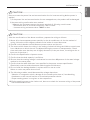
!
WARNING
When wiring:
Electrical shock can cause severe personal injury or death. Only a qualified, experienced electrician should attempt to wire this
system.
• Do not supply power to the unit until all wiring and tubing are completed or reconnected and checked.
• Highly dangerous electrical voltages are used in this system. Carefully refer to the wiring diagram and these instructions when
wiring. Improper connections and inadequate grounding can cause accidental injury or death.
• Ground the unit following local electrical codes.
• Connect all wiring tightly. Loose wiring may cause overheating at connection points and a possible fire hazard.
• The choice of materials and installations must comply with the applicable local/national or international standards.
When transporting:
Be careful when picking up and moving the indoor and outdoor units. Get a partner to help, and bend your knees when lifting to
reduce strain on your back. Sharp edges or thin aluminum fins on the air conditioner can cut your finger.
When installing...
... in a wall: Make sure the wall is strong enough to hold the unit's weight. It may be necessary to construct a strong wood or metal
frame to provide added support.
... in a room: Properly insulate any tubing run inside a room to prevent "sweating" that can cause dripping and water damage to wall
and floors.
... in moist or uneven locatinons: Use a raised concrete pad or concrete blocks provide a solid, level foundation for the outdoor unit.
This prevents water damage and abnormal vibration.
... in an area with high winds: Securely anchor the outdoor unit down with bolts and a metal frame. Provide a suitable air baffle.
... in a snowy area(for Heat Pump Model): Install the outdoor unit on a raised platform that is higher than drifting snow. Provide
snow vents.
When connecting refrigerant tubing
• Keep all tubing runs as short as possible.
• Use the flare method for connecting tubing.
• Check carefully for leaks before starting the test run.
When servicing
• Turn the power OFF at the main power box(mains) before opening the unit to check or repair electrical parts and wiring.
• Keep your fingers and clothing away from any moving parts.
• Clean up the site after you finish, remembering to check that no metal scraps or bits of wiring have been left inside the unit being
serviced.
!

TIPS FOR SAVING ENERGY 3
ENGLISH
• Do not cool excessively indoors. This may be harmful for your health and may consume more
electricity.
• Block sunlight with blinds or curtains while you are operating the air conditioner.
• Keep doors or windows closed tightly while you are operating the air conditioner.
• Adjust the direction of the air flow vertically or horizontally to circulate indoor air.
• Speed up the fan to cool or warm indoor air quickly, in a short period of time.
• Open windows regularly for ventilation as the indoor air quality may deteriorate if the air
conditioner is used for many hours.
• Clean the air filter once every 2 weeks. Dust and impurities collected in the air filter may block the
air flow or weaken the cooling / dehumidifying functions.
For your records
Staple your receipt to this page in case you need it to prove the date of purchase or for warranty
purposes. Write the model number and the serial number here:
Model number :
Serial number :
You can find them on a label on the side of each unit.
Dealer’s name :
Date of purchase :
Here are some tips that will help you minimize the power consumption when you use the air
conditioner. You can use your air conditioner more efficiently by referring to the instructions
below:
TIPS FOR SAVING ENERGY

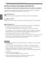
4IMPORTANT SAFETY INSTRUCTIONS
ENGLISH
IMPORTANT SAFETY INSTRUCTIONS
READ ALL INSTRUCTIONS BEFORE USING THE APPLIANCE.
Always comply with the following precautions to avoid
dangerous situations and ensure peak performance of your
product
WARNING
It can result in serious injury or death when the directions are
ignored
CAUTION
It can result in minor injury or product damage when the
directions are ignored
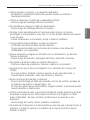
WARNING
• Installation or repairs made by unqualified persons can result
in hazards to you and others.
• Installation MUST conform with local building codes.
• The information contained in the manual is intended for use
by a qualified service technician familiar with safety
procedures and equipped with the proper tools and test
instruments.
• Failure to carefully read and follow all instructions in this
manual can result in equipment malfunction, property
damage, personal injury and/or death.
Installation
• Don’t use a power cord, a plug or a loose socket which is
damaged.
- Otherwise, it may cause a fire or electrical shock.
• For electrical work, contact the dealer, seller, a qualified
electrician, or an Authorized Service Center.
- Do not disassemble or repair the product. There is risk of fire
or electric shock.
!
!
!

IMPORTANT SAFETY INSTRUCTIONS 5
ENGLISH
• Always ground the product.
- There is risk of fire or electric shock.
• Install the panel and the cover of control box securely.
- There is risk of fire or electric shock.
• Always install a dedicated circuit and breaker.
- Improper wiring or installation may cause fire or electric
shock.
• Use the correctly rated breaker or fuse.
- There is risk of fire or electric shock.
• Do not modify or extend the power cable.
- There is risk of fire or electric shock.
• Do not let the air conditioner run for a long time when the
humidity is very high and a door or a window is left open.
- Moisture may condense and wet or damage furniture.
• Be cautious when unpacking and installing the product.
- Sharp edges could cause injury. Be especially careful of the
case edges and the fins on the condenser and evaporator.
• For installation, always contact the dealer or an Authorized
Service Center.
- There is risk of fire, electric shock, explosion, or injury.
• Do not install the product on a defective installation stand.
- It may cause injury, accident, or damage to the product.
• Be sure the installation area does not deteriorate with age.
- If the base collapses, the air conditioner could fall with it,
causing property damage, product failure, and personal
injury.
• There is a risk of fire and explosion.
- Inert gas (nitrogen) should be used when you check
plumbing leaks, cleaning or repairs of pipes etc.
If you are using combustible gases including oxygen,
product may have the risk of fires and explosions.
• Use a vacuum pump or Inert (nitrogen) gas when doing
leakage test or air purge. Do not compress air or Oxygen and
do not use Flammable gases. Otherwise, it may cause fire or
explosion.
- There is the risk of death, injury, fire or explosion.

6IMPORTANT SAFETY INSTRUCTIONS
ENGLISH
• Do not turn on the breaker or power under condition that front
panel, cabinet, top cover, control box cover are removed or
opened.
-
Otherwise, it may cause fire, electric shock, explosion or death.
-
For refrigerant leakage, consult your dealer. When the air
conditioner is to be installed in a small room, it is necessary to
take proper measures so that the amount of any leaked
refrigerant does not exceed the limiting concentration even
when it leaks. If the refrigerant leaks exceeding the level of
limiting concentration, an oxygen deficiency accident may
happen.
• The appliance shall be installed in accordance with the national
wiring regulation.
Operation
• Do not store or use flammable gas or combustibles near the
product.
- There is risk of fire or failure of product.
• Never use flammable spray such as hair spray, lacquer, or
paint near the unit.
• Tear apart and throw away plastic packaging bags so that
children will not play with them.
CAUTION
Installation
• Always check for gas (refrigerant) leakage after installation or
repair of product.
- Low refrigerant levels may cause failure of product.
• Install the drain hose to ensure that water is drained away
properly.
- A bad connection may cause water leakage.
• Keep level even when installing the product.
- To avoid vibration or water leakage.
• Use two or more people to lift and transport the product.
- Avoid personal injury.
• Do not install the unit in potentially explosive atmospheres.
!

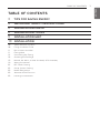
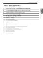
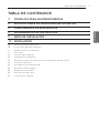
TABLE OF CONTENTS 7
ENGLISH
3TIPS FOR SAVING ENERGY
4IMPORTANT SAFETY INSTRUCTIONS
8INSTALLATION PARTS
8INSTALLATION TOOLS
9INSTALLATION MAP
10 INSTALLATION
10 Select the best Location
10 Fixing Installation Plate
11 Drill a Hole in the Wall
11 Flaring Work
12 Connecting the Piping
16 Checking the Drainage
18 Manual the decor, air filter Assembly & Disassembly
19 Wiring Connection
22 DIP Switch Setting
23 Group Control Setting
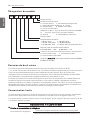
28 Model Designation
28 Airborne Noise Emission
28 Limiting concentration
TABLE OF CONTENTS

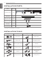
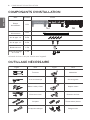
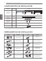
8INSTALLATION PARTS
ENGLISH
INSTALLATION TOOLS
Name Quantity Shape
Installation plate 1 EA
1 EA
Type "A" screw
5 EA
Type "C" screw
2 EA
Cloth tape 1 EA
1 EA
Drain hose
Conduit
mounting plate
SJ SK
Cloth tape is not attached to the product.
Figure FigureName
Screw driver
Electric drill
Measuring tape, Knife
Hole core drill
Spanner
Torque wrench
Multi-meter
Hexagonal wrench
Ammeter
Gas-leak detector
Thermometer,
Level
Flaring tool set
Name
INSTALLATION PARTS

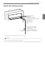
INSTALLATION MAP 9
ENGLISH
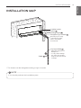
INSTALLATION MAP
Vinyl tape (Wide)
• Apply after carrying out a
drainage test.
• To carry out the drainage
test, remove the air filters
and pour water into the heat
exchanger.
Saddle
Installation plate
Sleeve
Bushing-Sleeve
Putty(Gum Type Sealant)
Bend the pipe as closely
on the wall as possible,
but be careful that it
doesn't break.
NOTE
!
• You should purchase the installation parts.
* The feature can be changed according to type of model.

10 INSTALLATION
ENGLISH
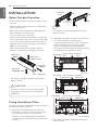
Select the best Location
- There should not be any heat or steam near
the unit.
- Select a place where there are no obstacles
around of the unit.
- Make sure that condensation drainage can
be conveniently routed away.
- Do not install near a doorway.
- Ensure that the interval between a wall and
the left (or right) of the unit is more than 100
mm. The unit should be installed as high as
possible on the wall, allowing a minimum of
200 mm from ceiling.
- Use a metal detector to locate studs to
prevent unnecessary damage to the wall.
* The feature can be changed according to
type of model.
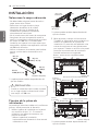
Fixing Installation Plate
The wall you select should be strong and solid
enough to prevent vibration
1Mount the installation plate on the wall
with type "A" screws. If mounting the unit
on a concrete wall, use anchor bolts.
- Mount the installation plate horizontally
by aligning the centerline using Horizontal
meter .
* The feature can be changed according to
type of model.
2Measure the wall and mark the centerline.
It is also important to use caution
concerning the location of the installation
plate. Routing of the wiring to power
outlets is through the walls typically.
Drilling the hole through the wall for piping
connections must be done safely.
More than
200(7-14/16)
More than
More than
100(4)
100(4)
More than
2300(90-9/16)
Unit : mm(inch)
CAUTION
Install the indoor unit on the wall where
the height from the floor is more than
2300 mm.
!
INSTALLATION
Ø65
(Ø2-9/16)
152(6) 98(3-7/8) 134(5-1/4)
194(7-5/8)
Right rear piping
Left rear piping
Place a level on raised tab
Unit Outline
418(16-7/16) 418(16-7/16)
Installation Plate
Ø65
(Ø2-9/16)
Ø 65
113 76 134 178
Ø 65
Right rear piping
Left rear piping
Place a level on raised tab
Unit Outline 407 397
Unit : mm
Installation
Plate
Chassis
Hook
Type
"A" Screws
Tubatura posteriore sinistra
Measuring
Tape
Measuring Tape
Hanger
Right rear piping
Place a level on raised tab
Unit Outline
Unit : mm(inch)
494(19-7/16)
504(19-7/8)
134(5-1/4)
150(5-7/8)
83(3-1/4)
83(3-1/4)
83(3-1/4)
Ø
65
65
(Ø
2-9/16)
2-9/16)
Ø65
(Ø2-9/16)
Ø
65
65
(Ø
2-9/16)
2-9/16)
Ø65
(Ø2-9/16)
83(3-1/4)
83(3-1/4)
83(3-1/4)
* The feature can be changed according to
type of model.

INSTALLATION 11
ENGLISH
Drill a Hole in the Wall
- Drill the piping hole with a Ø 65 mm hole
core drill. Drill the piping hole at either the
right or the left with the hole slightly slanted
to the outdoor side.
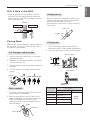
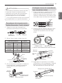
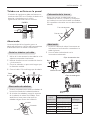
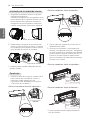
Flaring Work
Main cause for gas leakage is due to defect of
flaring work. Carry out correct flaring work in
the following procedure.
1Use the piping kit accessory or the pipes
purchased locally.
2Measure the distance between the indoor
and the outdoor unit.
3Cut the pipes a little longer than measured
distance.
4Cut the cable 1.5m longer than the pipe
length.
1. Completely remove all burrs from the cut
cross section of pipe/tube.
2. While removing burrs put the end of the
copper tube/pipe in a downward direction
while removing burrs location is also
changed in order to avoid dropping burrs
into the tubing.
- Remove flare nuts attached to indoor and
outdoor unit, then put them on pipe/tube
having completed burr removal.
(not possible to put them on after finishing
flare work)
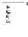
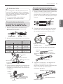
1
Firmly hold copper pipe in a bar with the
dimension shown in below table table below.
2Carry out flaring work with the flaring tool.
5-7mm
(3/16"~5/16")
Indoor
WALL
Outdoor
Cut the pipes and the cable
Copper
pipe
90 °
Slanted Uneven Rough
Burrs removal
Putting nut on
Flaring work
Pipe
Reamer
Point down
Flare nut
Copper tube
Bar
Copper pipe
"A"
<Wing nut type>
<Clutch type>
Pipe diameter
Inch (mm)
A inch (mm)
Wing nut type Clutch type
Ø 1/4 (Ø 6.35)
0.04~0.05 (1.1~1.3)
0~0.02
(0~0.5)
Ø 3/8 (Ø 9.52)
0.06~0.07 (1.5~1.7)
Ø 1/2 (Ø 12.7)
0.06~0.07 (1.6~1.8)
Ø 5/8 (Ø 15.88)
0.06~0.07 (1.6~1.8)
Ø 3/4 (Ø 19.05)
0.07~0.08 (1.9~2.1)

12 INSTALLATION
ENGLISH
1Compare the flared work with the figure
by.
2If a flared section is defective, cut it off
and do flaring work again.
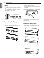
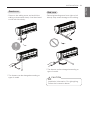
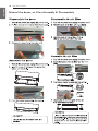
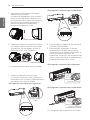
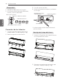
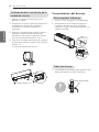
Connecting the Piping
1Pull the cover at the bottom of the indoor
unit. Pull the cover ① → ②.
2Remove the cover from the indoor unit.
3Pull back the tubing holder.
4Remove pipe port cover and positioning
the tubing
* The feature can be changed according to
type of model.
1Insert 3 hooks of the chassis cover into
gap of the chassis certainly.
2Push the hooks to assemble chassis
cover. Push the chassis cover ① → ②.
Check
Inclined
Inside is shiny without scratches
Smooth all round
Even length
all round
Surface
damaged Cracked Uneven
thickness
= Improper flaring =
ڸڸڸ
ڹ
ڹ
Right
Indoor unit back side view Tubing holder
Downwards
Left
Backwards
Assembly of chassis cover
ڹ
ڹ
ڸڸ
ڸڸ

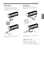
INSTALLATION 13
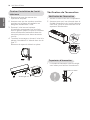
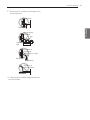
ENGLISH
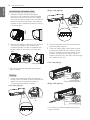
- Press on the tubing cover and unfold the
tubing to downward slowly. And then bend
to the left side slowly.
* The feature can be changed according to
type of model.
- Following bending case from right to left
directly may cause damage to the tubing.
* The feature can be changed according to
type of model.
Good case Bad case
CAUTION
Installation Information. For right piping.
Follow the instruction above.
!

14 INSTALLATION
ENGLISH
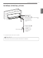
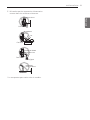
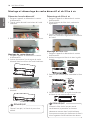
Installation of Indoor Unit
1Hook the indoor unit onto the upper
portion of the installation plate.( engage
the three hooks at the top of the indoor
unit with the upper edge of the installation
plate) Ensure that the hooks are properly
seated on the installation plate by moving
it left and right
2Unlock the tubing holder from the chassis
and mount between the chassis and
installation plate in order to separate the
bottom side of the indoor unit from the
wall.
* The feature can be changed according to
type of model.
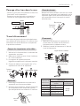
Piping
1Insert the connecting cable through the
bottom side of indoor unit and connect the
cable (You can see detail contents in
'Connecting the cables' section)
<Left side piping>
<Right side piping>
2Secure the cable onto the control board
with the cable retainer.
3Tape the tubing pipe, drain hose and the
connection cable. Be sure that the drain
hose is located at the lowest side of the
bundle. Locating at the upper side can
cause overflow from the drain pan through
the inside of the unit.
<Left side piping>
<Right side piping>
* The feature can be changed according to
type of model.
View Slide up the metal
plate cover
Terminal block of indoor unit
L(L1) N(L2) 3(A) 4(B)
Indoor power input Outdoor unit
Installation plate
Tubing Holder
View Slide up the metal
plate cover
Terminal block of indoor unit
L(L1) N(L2) 3(A) 4(B)
Indoor power input Outdoor unit
Connecting pipe
Connecting
cable
Tape
Drain hose
Connecting pipe
Connecting
cable
Tape
Drain hose

INSTALLATION 15
ENGLISH
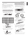
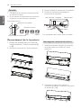
1Align the center of the pipes and
sufficiently tighten the flare nut by hand
2Tighten the flare nut with a wrench
3When needed to extend the drain hose of
indoor unit, assembly the drain pipe as
shown on the drawing
Wrap the insulation material
around the connecting portion.
1Overlap the connection pipe insulation
material and the indoor unit pipe insulation
material. Bind them together with vinyl
tape so that there may be no gap.
2Set the tubing cutting line upward.
Wrap the area which accommodates the
rear piping housing section with vinyl tape.
3For left rear piping, bundle the piping and
drain hose together by wrapping them
cloth tape over the range within which
they fit into the rear piping housing
section.
* Wrap the piping of the indoor unit that are
visible from the outside with vinyl tape.
CAUTION
If the drain hose is routed inside the room
insulate the hose with an insulation material*
so that dripping from sweating condensation)
will not damage furniture or floors.
* Foamed polyethylene or equivalent is
recommended.
!
Outside diameter Torque
Connecting the installation pipe
and drain hose to the indoor unit.
Indoor unit tubing Flare nut Pipes
mm inch kgf.m
Ø6.35 1/4 1.8~2.5
Ø9.52 3/8 3.4~4.2
Ø12.7 1/2 5.5~6.5
Ø15.88 5/8 6.3~8.2
Ø19.05 3/4 9.9~12.1
Torque wrench
Indoor unit tubing
Open-end wrench
(fixed)
Connection pipe
Flare nut
Vinyl tape(narrow)
Adhesive
Drain pipe
Indoor unit drain hose
Insulation material
Gas Pipe Liquid Pipe
Cutting Line
Cutting Line
Good Case Bad Case
* Tubing cutting line have to be upward.
Vinyl tape(narrow)
Connection pipe
Connecting cable
Vinyl tape (wide) Wrap with vinyl tape
Indoor unit pipe
Pipe
Wrap with cloth tape
Drain hose
Pipe
Cloth tape

16 INSTALLATION
ENGLISH
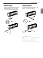
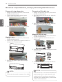
Type 'C' screw
Finishing the indoor unit
installation
1Mount the tubing holder in the original
position.
2Ensure that the hooks are properly seated
on the installation plate by moving it left
and right.
3Press the lower left and right sides of the
unit against the installation plate until the
hooks engage into their slots (clicking
sound).
4Finish the assembly by screwing the unit
to the installation plate by using two
pieces of type "C" screws. And assemble a
chassis cover.
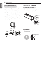
Checking the Drainage
To check the drainage
1Pour a glass of water on the evaporator.
2Ensure the water flows through the drain
hose of the indoor unit without any
leakage and goes out the drain exit.
Drain piping
1The drain hose should point downward for
easy drain flow.
Drain pan
Drain
hose
Leakage
checking
Connecting area
drain hose
Leakage
checking
Downward slope

INSTALLATION 17
ENGLISH
2Do not make drain piping like the
following.
* The feature can be changed according to
type of model.
Do not raise
Water
leakage
Accumulated
drain water
Air
Waving
Water
leakage
Tip of drain hose
dipped in water
Water
leakage Ditch
Less than
50mm gap

18 INSTALLATION
ENGLISH
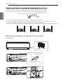
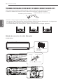
Manual the decor, air filter Assembly & Disassembly

INSTALLATION 19
ENGLISH
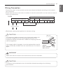
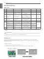
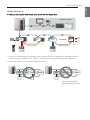
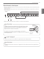
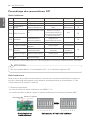
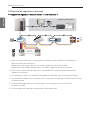
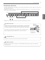
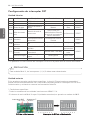
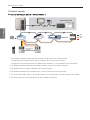
Wiring Connection
- Connect the wires to the terminals on the control board individually according to the outdoor
unit connection.
- Ensure that the color of the wires of outdoor unit and the terminal No. are the same as those of
indoor unit respectively.
※Resistance measurement position for incorrect wiring.
Terminal block of indoor unit
Terminal block of outdoor unit
L(L1) N(L2) 3(A) 4(B)
Indoor power input
SJ/SK
IDU IDU
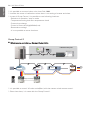
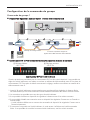
Outdoor unit Indoor unit
Central controller
ODU ODU
DRY1 DRY2 GND
INTERNET 12V
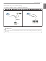
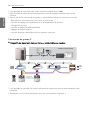
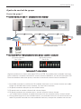
CAUTION
The Power cord connected to the unit should be selected according to the following
specifications.
!
CAUTION
The connecting cable connected to the indoor and outdoor unit
should be complied with the following specifications (This
equipment shall be provided with a cable set complying with the
national regulation).
If the supply cable is damaged, it must be replaced by a special
cable or assembly available from the manufacturer of its service
agent.
!
WARNING
!
Make sure that the screws of the terminal are free from looseness.
NORMAL
CROSS-SECTIONAL
AREA 0.75 mm
2
20 mm
35±5 mm
GN/YL
10±3 mm

20 INSTALLATION
ENGLISH
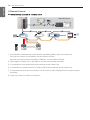
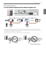
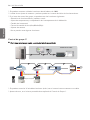
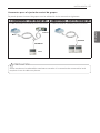
Precautions when laying power and ground wiring
Use round pressure terminals for connections to the power terminal block.
When laying ground wiring, you must use round pressure terminals.
Round pressure terminal Power wire (Ground wire)
When none are available, follow the instructions below.
- Do not connect wiring of different thicknesses to the power terminal block. (Slack in the power
wiring may cause abnormal heat.)
- When connecting wiring which is the same thickness, do as shown in the figure below.
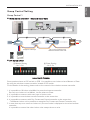
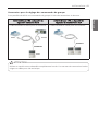
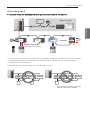
Connection method of the connecting cable(Example)
SJ/SK Chassis
3(A) 4(B)
Power Supply
High Voltage
Transmission
Lock nut
Conduit mounting plate
Conduit
L(L1)
N(L2)
La page est en cours de chargement...
La page est en cours de chargement...
La page est en cours de chargement...
La page est en cours de chargement...
La page est en cours de chargement...
La page est en cours de chargement...
La page est en cours de chargement...
La page est en cours de chargement...
La page est en cours de chargement...
La page est en cours de chargement...
La page est en cours de chargement...
La page est en cours de chargement...
La page est en cours de chargement...
La page est en cours de chargement...
La page est en cours de chargement...
La page est en cours de chargement...
La page est en cours de chargement...
La page est en cours de chargement...
La page est en cours de chargement...
La page est en cours de chargement...
La page est en cours de chargement...
La page est en cours de chargement...
La page est en cours de chargement...
La page est en cours de chargement...
La page est en cours de chargement...
La page est en cours de chargement...
La page est en cours de chargement...
La page est en cours de chargement...
La page est en cours de chargement...
La page est en cours de chargement...
La page est en cours de chargement...
La page est en cours de chargement...
La page est en cours de chargement...
La page est en cours de chargement...
La page est en cours de chargement...
La page est en cours de chargement...
La page est en cours de chargement...
La page est en cours de chargement...
La page est en cours de chargement...
La page est en cours de chargement...
La page est en cours de chargement...
La page est en cours de chargement...
La page est en cours de chargement...
La page est en cours de chargement...
La page est en cours de chargement...
La page est en cours de chargement...
La page est en cours de chargement...
La page est en cours de chargement...
La page est en cours de chargement...
La page est en cours de chargement...
La page est en cours de chargement...
La page est en cours de chargement...
La page est en cours de chargement...
La page est en cours de chargement...
La page est en cours de chargement...
La page est en cours de chargement...
La page est en cours de chargement...
La page est en cours de chargement...
La page est en cours de chargement...
La page est en cours de chargement...
La page est en cours de chargement...
La page est en cours de chargement...
La page est en cours de chargement...
La page est en cours de chargement...
La page est en cours de chargement...
-
 1
1
-
 2
2
-
 3
3
-
 4
4
-
 5
5
-
 6
6
-
 7
7
-
 8
8
-
 9
9
-
 10
10
-
 11
11
-
 12
12
-
 13
13
-
 14
14
-
 15
15
-
 16
16
-
 17
17
-
 18
18
-
 19
19
-
 20
20
-
 21
21
-
 22
22
-
 23
23
-
 24
24
-
 25
25
-
 26
26
-
 27
27
-
 28
28
-
 29
29
-
 30
30
-
 31
31
-
 32
32
-
 33
33
-
 34
34
-
 35
35
-
 36
36
-
 37
37
-
 38
38
-
 39
39
-
 40
40
-
 41
41
-
 42
42
-
 43
43
-
 44
44
-
 45
45
-
 46
46
-
 47
47
-
 48
48
-
 49
49
-
 50
50
-
 51
51
-
 52
52
-
 53
53
-
 54
54
-
 55
55
-
 56
56
-
 57
57
-
 58
58
-
 59
59
-
 60
60
-
 61
61
-
 62
62
-
 63
63
-
 64
64
-
 65
65
-
 66
66
-
 67
67
-
 68
68
-
 69
69
-
 70
70
-
 71
71
-
 72
72
-
 73
73
-
 74
74
-
 75
75
-
 76
76
-
 77
77
-
 78
78
-
 79
79
-
 80
80
-
 81
81
-
 82
82
-
 83
83
-
 84
84
-
 85
85


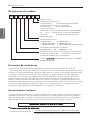
LG ARNU093SJS4 Guide d'installation
- Catégorie
- Climatiseurs split-system
- Taper
- Guide d'installation
- Ce manuel convient également à
dans d''autres langues
- English: LG ARNU093SJS4 Installation guide
- español: LG ARNU093SJS4 Guía de instalación