
USER GUIDE
InterMetro Industries Corporation
North Washington Street, Wilkes-Barre, PA USA 18705
For Product Information Call: 1-800-992-1776
Visit Our Web Site: www.metro.com
MAINTENANCE
REPLACEMENT PARTS
USER GUIDE
BRAKE / SWIVEL LOCK SYSTEM
MODELS: BL6P24, BL8P24, 6P, 6PR, 8P, 8PR
This User Guide is Sectionalized into "Instructions For Use",
"Maintenance Procedure" and "Replacement Parts List"
Brake / Swivel Lock System

Brake / Swivel Lock System
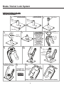
INSTRUCTIONS FOR USE
Main
Stud
Brake / Swivel Caster
Plate Assembly
1
Pivot Pin
Swivel Caster
Plate Assembly
2
Inner Race
3
Thrust
Bearing
Thrust
Washer
4
CARE MUST BE
TAKEN WHEN
INSERTING
SEALS, O-RINGS
AND WASHERS
TO AVOID
DAMAGE AND
ASSURE A
PROPER SEAL
5
6" / 8"
Caster
Horn
Seal
(Flange Up)
6
7
8
O-Ring
Flat
Washer
Nut
9
10
Tighten Nut to
170 ft. lbs Torque
GREASE THE
CASTER HORN
REFER TO
PAGES 8-9
Main
Stud
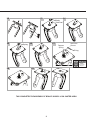
CASTER HORN ASSEMBLY
2
11
Swivel Caster Assembly
Brake / Swivel Caster Assembly
Brake Shoe
Assembly
Plain Brake
Shoe

12 13 14
Brake
Stud Seal
15
16
Spring
1
2
Depress
Spring
Insert Into
Groove
17
E-ring
18 19
THIS COMPLETES THE ASSEMBLY OF BRAKE / SWIVEL LOCK CASTER HORN
3
RISK OF EYE
INJURY
Eye Protection
Required

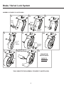
Brake / Swivel Lock System
ASSEMBLY OF WHEEL TO CASTER HORN
Plain
Axle
1
2
Spacer
Retainer
Washer
3
4
5
6
6" / 8"
Poly
Wheel
Spacer
Retainer
Washer
7
8
Nut
GREASE THE
CASTER WHEEL
REFER TO
PAGES 8-9
Tighten Nut to
30 ft. lbs Torque
THIS COMPLETES THE ASSEMBLY OF WHEEL TO CASTER HORN
4
9

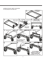
ASSEMBLY OF BRAKE / SWIVEL LOCK SYSTEM
Two People Required to Assemble Unit.
1
2
INVERT DOLLY
ASSEMBLY
Brake / Swivel
Lock Casters
3
Nut (x4)
Washer(x4)
Screw
(x4)
Tighten Nuts
Completely
4
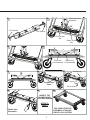
TURN THE DOLLY
UPRIGHT AND
POSITION CASTERS
5
6
7
Brake Torsion
Bar
APPLY
GREASE
Pivot Torsion
Bar
8
9
10
Spring
Pivot Pin
TAP THE BRIDGE
TOWARDS OUTSIDE FOR
FREE UP AND DOWN
MOVEMENT OF PIVOT PIN
5
FOR GREASE SPECS
REFER TO PAGE 8

Brake / Swivel Lock System
SWIVEL
BRAKE
ON
OFF
ON
OFF
12
13
11
Ramp
Left Side
Right Side
Right Side
Cover Top
Cam Wire -
Brake Lock
Cover Top
Cam Wire -
Pivot Lock
Left Side
14
Shaft
Spacer
15
SWIVEL
BRAKE
16
Pedal Assembly
SWIVEL
BRAKE
17
TURN COVER
UPRIGHT
SWIVEL
BRAKE
18
Washer (x4)
Acorn Nut
(x4)
SWIVEL
BRAKE
19
SWIVEL
BRAKE
BRAKE
20
Left Side
Right Side
COVER
6
Apply Loctite No.271

SWIVEL
BRAKE
21
90°
22
End Gasket
End Gasket
Pivot Torsion
Bar
Brake Torsion
Bar
Pivot Lock Cam
Assembly
23
24
Pivot Lock
Cam Assembly
Brake Lock
Cam Assembly
25
SWIVEL
BRAKE
26
Outside Legs
Down
SWIVEL
BRAKE
27
Washer (x4)
Nut (x4)
Screw (x4)
SWIVEL
BRAKE
28
Tighten Nuts
Completely
29
INSPECT THE
BRAKE/SWIVEL
LOCK MECHANISM
REFER TO
PAGE 9
30
THIS COMPLETES THE
ASSEMBLY OF BRAKE /
SWIVEL LOCK SYSTEM
7

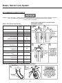
RECOMMENDED MAINTENANCE
Regularly inspect the casters. Tighten loose fasteners and replace worn or damaged parts with new InterMetro approved
parts. For mobile units, replace worn or damaged casters immediately; lubricate casters regularly.
Use EP1 grease or equivalent.
Table 1: EP1 Grease Specication
TEST DESCRIPTION ASTM
TEST
METHOD
PROPERTIES
TYPE OF SOAP CALCIUM
COMPLEX
Mineral Oil Viscosity, SUS, @ 100° F D88 500
Color Brown
Oxidation Inhibitors Present
Penetration -
Worked 60 Strokes
Worked 100, 000 Strokes
% Change from 60 Strokes
D217
313
275
12.1
Dropping Point, ° F D566 500+
Oil Separation, % D1742 0.95
Four Ball Wear Test
(1200 rpm, 1hr., 40 kg., 75° C) -
Scar Diameter (mm)
D2266
0.46
Four Ball EP Test (U.S. Steel Method)
-
Load Wear Index
Weld Point, kg.
40.0
260
Timken EP Test, lbs. D2509 50
Wheel Bearing Test
(60 mph [660rpm] @ 250° F) -
Leakage, gms.
D1263
0.8
Oxidation Stability -
100 hrs., psi drop
500 hrs., psi drop
D942
1
4
Water Washout Test -
% Loss @ 75° F
D1264
10.0
NLG1 Grade No.1
Brake / Swivel Lock System
Swivel
Seal
1
2
3
INSPECTION OF GREASE EP1 IN CASTER HORN
AND WHEEL ASSEMBLY
Roll Back
The Flange
of Swivel
Seal
FRONT
VIEW
Bearing
Caster
Plate
Area Where
Grease
Is Visible
Around
Bearing And
Caster Plate
IF GREASE IS
NOT VISIBLE
IN STEP 3
FOLLOW THE
PROCEDURE
IN PAGES 8 - 9
4
Grease
Fitting
APPLYING GREASE EP1 IN CASTER HORN AND WHEEL ASSEMBLY
2
LOCATION
DO NOT OVER GREASE
TO WHERE GREASE
IS ESCAPING FROM
BETWEEN THE SWIVEL
SEAL AND CASTER
PLATE.
1
8
GREASE
THE CASTER
HORN

O-Ring
(Installed In Step8
of Page2)
Grease Flows In
Upward Direction
Grease Flows In Downward
Direction. Replace O-Ring
O-Ring Properly Installed
O-Ring Not Properly
Installed (Or) Defective
3
SECTIONAL VIEW
4
GREASE THE
CASTER WHEEL
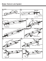
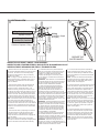
INSPECTION OF BRAKE / SWIVEL LOCK ASSEMBLY
INSPECTION DE L’ENSEMBLE FREIN / DISPOSITIF DE BLOCAGE BASCULANT
INSPECCIÓN DEL MECANISMO DE FRENO / TRABA DE RUEDA
1. With the inside end of the swivel pedal on the left hand
side of the dolly depressed toward the U channel, swivel
both casters. The casters must rotate freely through
360 degrees and there will be no drag or momentary
hesitation in the rotation.
NOTE: If a drag or momentary hesitation exists, it is an
indication that the pivot pin is extending down too far in
the mechanism. Disassemble the cover and recheck
STEP 10 of PAGE 5.
2. Check the swivel locking system by depressing the
outside end of the pedal on the left side of the dolly
toward the U channel. Swivel both casters. If the
mechanism is working correctly for this mode, the pivot
pins will drop into position locking the casters in a front to
back direction of the dolly. The casters will lock into this
position in two modes. One being with the swivel radii of
the casters toward the center of the dolly, and the other
with the swivel radii toward the outside end of the dolly.
NOTE: If the swivel lock does not work of the two modes,
tap the caster at the caster plate area tightly with a
hammer in the direction toward the inside of the dolly. If
the swivel lock action still does not work, it is an indication
that the pivot pin is not dropping down far enough in the
mechanism. Disassemble the cover and recheck STEP
10 of PAGE 5.
3. Check the brake action by depressing the inside end
of the brake pedal on the right hand side of the dolly
toward the U channel. If the mechanism is working
correctly the brake shoe will extend down, engaging and
locking the wheels.
NOTE: If the brake lock action does not work either
wheel, tap the caster at the caster plate area lightly with a
hammer in the direction toward the inside of the dolly.
1. Con el lado interno del pedal a la izquierda del
carrito presionado hacia el perl U, girar ambas
ruedas. Las ruedas deben girar libremente los 360
grados sin impedimentos o resistencia momentánea
al movimiento.
NOTA: Si hubiera una resistencia momentánea al
movimiento signica que el pasador de la rótula no
llega tan abajo como debe llegar. Quitar la tapa y
repetir el PASO 10 de la Página 5.
2. Probar el mecanismo de traba presionando el lado
externo del pedal a la izquierda del carrito, hacia el
perl U. Girar ambas ruedas. Si el mecanismo está
funcionando correctamente, los pasadores de la
rótula caerán para bloquear las ruedas en dirección
de avance y retroceso. Las ruedas se bloquearán
de dos maneras: Una es con la circunferencia de la
rótula hacia el centro del carrito y la otra es con la
circunferencia de la rótula hacia afuera.
NOTA: Si el bloqueo no funciona de las dos maneras,
golpear la placa de apoyo de la rueda hacia el lado
interno del carrito. Si el bloqueo de la rótula continúa
sin funcionar, signica que el pasador no llega tan
abajo como debe llegar. Quitar la tapa y repetir el
PASO 10 de la página 5.
3. Probar el mecanismo de freno presionando el
lado interno del pedal ubicado en la parte derecha
del carrito, hacia el perl U. Si el mecanismo está
funcionando correctamente, la zapata de freno de
extenderá hacia abajo para bloquear las ruedas.
NOTA: Si el freno no funciona en ninguna rueda,
golpear la placa de apoyo de la rueda hacia el lado
interno del carrito.
1. L’extrémité intérieure de la pédale basculante
située sur le côté gauche du chariot étant enfoncée
en direction du prolé en U, faire pivoter les deux
roulettes. Les roulettes doivent pivoter sans
résistance de 360 degrés et il ne doit se produire
aucune résistance ou ralentissement momentané
dans la rotation.
REMARQUE: IUne résistance ou un ralentissement
momentané indique que l’axe du pivot descend trop
bas dans le mécanisme. Démonter le couvercle et
vérier à nouveau L’ÉTAPE 10 de la PAGE 5.
2. Vérier le système de blocage basculant en
appuyant sur l’extrémité extérieure de la pédale
située du côté gauche du chariot en direction
du prolé. Faire pivoter les deux roulettes. Si le
mécanisme fonctionne correctement pour ce mode,
les axes de pivot descendront en position pour bloquer
les roues dans la direction avant à arrière du chariot.
Les roulettes se bloqueront dans cette position dans
les deux modes. L’un étant le rayon des roulettes
vers le centre du chariot et l’autre avec le rayon vers
l’extrémité extérieure du chariot.
REMARQUE: Si le blocage basculant ne fonctionne
dans aucun des deux modes, taper légèrement sur
la plaque de la roulette avec un marteau en direction
de l’intérieur du chariot. Si le dispositif de blocage
basculant ne fonctionne toujours pas, cela indique
que l’axe de pivot ne descend pas assez loin dans
le mécanisme. Démonter le couvercle et vérier à
nouveau l’ÉTAPE 10 de la PAGE 5.
3. Vérier le fonctionnement du frein en appuyant
sur l’extrémité intérieure de la pédale de frein du
côté droit du chariot en direction du prolé en U. Si le
mécanisme fonctionne correctement, le sabot du frein
s’abaissera, s’engagera et bloquera les roues.
REMARQUE: Si l’action de blocage du frein ne
fonctionne sur aucune roue, taper légèrement sur la
roulette avec un marteau au niveau de la plaque de la
roulette en direction de l’intérieur du chariot.
9

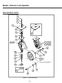
REPLACEMENT PARTS
1010
1
2
3
4-1
5
6
5
7
4-2
8-1
11
12
13
14-1
15
16
17
17
19
16
20
8-2
14-2
18-1
18-2
21-1
21-2
21-3
21-4
21-5
21-6
NOTE:
Items 18-1 / 18-2 Are Supplied From
The Factory Along With Item 19.
Figure 1 - Caster Assembly
Brake / Swivel Lock System
10

22
23
24
25
26
25
26
27
28
29
28
32
31
30
32
30
33
31
33
34-1
34-2
35-1
35-2
34-3
34-4
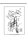
For Illustrative
Purpose Only
Figure 2 - Swivel / Brake Lock Assembly
11

InterMetro Industries Corporation
North Washington Street, Wilkes-Barre, PA USA 18705
For Product Information Call: 1-800-992-1776
Visit Our Web Site: www.metro.com
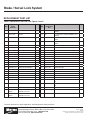
REPLACEMENT PART LIST
Table 2: Replacement Parts No.s for Figures 1 and 2
Item
No.
Replace-
ment
Part No:
Description Qty. Item
No.
Replace-
ment Part
No:
Description Qty.
1 RPF07-009 E-RING 1 21-3 6P 6" COMPLETE CASTER ASSEMBLY POLY
SWIVEL
1
2 RPC10-006 SPRING 1 21-4 8P 8" COMPLETE CASTER ASSEMBLY POLY
SWIVEL
1
3 RPC08-005 BRAKE STUD SEAL 1 21-5 6PR 6" COMPLETE CASTER ASSEMBLY POLY
RIGID
1
4-1 RPBL00-110L CASTER PLATE (BRAKE) 1 21-6 8PR 8" COMPLETE CASTER ASSEMBLY POLY
RIGID
1
4-2 RPS000-110L CASTER PLATE (SWIVEL) 1 22 RPBL50-1102 24" PIVOT LOCK CAM ASSEMBLY 1
5 RPC01-010 THRUST WASHER 2 23 RPBL50-1105 24" BRAKE TORSION BAR ASSEMBLY 1
6 RPC01-009 THRUST BEARING 1 24 RPBL50-1108 PIVOT TORSION BAR ASSEMBLY 1
7 RPC08-001 SWIVEL SEAL 1 25 RPC11-055 PIVOT PIN 2
8-1 RPS600-1101 HORN (BRAKE/SWIVEL) - 6" 1 26 RPC10-006 SPRING 2
8-2 RPS800-1101 HORN (BRAKE/SWIVEL) - 8" 1 27 RPBL50-1104 BRAKE LOCK CAM ASSEMBLY 1
10 RPC11-056 INNER RACE 1 28 RPC06-830 END GASKET COVER 2
11 RPC08-009 O-RING 1 29 RPBL50-1011 COVER 1
12 RPF06-030 WASHER 1 30 RPF02-017A ACORN NUT, 5/16-18 4
13 RPF02-007 HEX JAM NUT 5/8-18 1 31 RPF06-044 WASHER 4
14-1 RPBLBS-1101 BRAKE SHOE ASSEMBLY 1 32 RPC11-031 SHAFT SPACER 4
14-2 RPC03-016 BRAKE SHOE PLAIN 1 33 RPBL30-1100 PEDAL ASSEMBLY 2
15 RPF04-002 AXLE PLAIN 1 34-1 RPS600-1100 6" CASTER HORN ASSEMBLY - SWIVEL 1
16 RPC11-026A SPACER 2 34-2 RPS800-1100 8" CASTER HORN ASSEMBLY - SWIVEL 1
17 RPF06-003 WHEEL RETAINER WASHER 2 34-3 RPBL60-1100 6" CASTER HORN ASSEMBLY - B.L 1
18-1 RPC02-105 6" POLY WHEEL 1 34-4 RPBL80-1100 8" CASTER HORN ASSEMBLY - B.L 1
18-2 RPC02-108 8" POLY WHEEL 1 35-1 BL6P 6" COMPLETE CASTER ASSEMBLY POLY
B.L
2
19 RPC02-106A SPANNER BUSHING 1 35-2 BL8P 8" COMPLETE CASTER ASSEMBLY POLY
B.L
2
20 RPF02-023 AXLE NUT 1
21-1 BL6P_LESS_
MECH
6" COMPLETE CASTER
ASSEMBLY POLY B.L
1
21-2 BL8P_LESS_
MECH
8" COMPLETE CASTER
ASSEMBLY POLY B.L
1
Brake / Swivel Lock System
L01-010 Rev. D
03/2018
Information and specications are subject to change
without notice. Please conrm at time of order.
*Save this document for future application, load rating and/or safety reference.
-
 1
1
-
 2
2
-
 3
3
-
 4
4
-
 5
5
-
 6
6
-
 7
7
-
 8
8
-
 9
9
-
 10
10
-
 11
11
-
 12
12


