AntennaCraft Mini State 5MS9000 Manuel utilisateur
- Taper
- Manuel utilisateur

HDTV Ready
Amplified UHF/VHF
Indoor/Outdoor TV Antenna
with Internal Rotator
Model 5MS9000
AC/DC Remote Controlled for
RV, Boat or Home
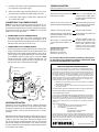
Your Antennacraft Mini-State Directional, Rotating Antenna
provides excellent reception of VHF/UHF TV channels in most
viewing locations. The UV protective housing is made of im-
pact-resistant filled co-polymer, making the exterior resistant
to weathering. It features both AC and DC operation and is
excellent for use on recreational vehicles, boats, or in the
home.
The VHF section is a circular shaped, slot tuned, broadband,
unidirectional traveling wave antenna. The UHF section is a
broadband, multi-element array. Both UHF and VHF signals
are amplified with a built-in split-band amplifier that provides
up to 20 dB gain.
The Mini-State Antenna system is designed for long life and
requires no routine maintenance. Should the unit ever quit
working, refer to the troubleshooting tips to help determine
possible causes. Do not attempt to service this product your-
self, as opening or removing covers may expose you to dan-
gerous voltage or other hazards. Refer all servicing to quali-
fied service personnel.
WARNING: INSTALLATION OF
THIS PRODUCT NEAR POWERLINES
IS DANGEROUS. FOR YOUR SAFETY,
FOLLOW THE INSTALLATION
DIRECTIONS
CAUTION
WARNING:
To reduce the risk of fire or electric shock, do not expose this
appliance to rain or moisture.
RISK OF ELECTRIC SHOCK DO NOT OPEN
CAUTION:
Use of controls or adjustments or performance of procedures
other than those specified may result in hazardous radiation
exposure.
CAUTION: TO REDUCE THE RISK OF ELECTRIC
SHOCK, DO NOT REMOVE COVER (OR BACK).
NO USER-SERVICING. REFER ALL SERVICING TO
QUALIFIED SERVICE PERSONNEL.
The lightning flash with arrowhead symbol, within an equilateral
triangle is intended to alert the user to the presence of unin-sulated
“dangerous voltage” within the product’s enclosure that may be
of significant magnitude to constitute a risk of electric shock to
persons.
The exclamation point within an equilateral triangle is intended
to alert the user to the presence of important operating and main-
tenance (servicing) instructions in the literature accompanying
the appliance.
BEFORE INSTALLATION
Note: to CATV SYSTEM INSTALLER
Article 820-40 of the NEC specified that the cable ground shall
be connected to the grounding system of the building “as close
to the point of cable entry as practical”.
Note: Do not plug your Mini-State power supply into an AC out-
let or DC power source until all electrical and antenna connec-
tions have been made. Doing so may short out the power sup-
ply/transformer and void your warranty.
Included in the Mini-State Antenna System:
• VHF/UHF antenna with amplifier and internal rotator
• Remote hand control unit with 8’ cable
• 12 VDC/120 VAC power supply unit
• 12VDC Adapter with fused powercord
• 60’ combination coaxial/3-wire rotator cable
• Stainless steel mounting hardware kit
MINI STATEMINI STATEMINI STATE
MINI STATEMINI STATE

1. READ INSTRUCTIONS—All the safety and operating instructions should be read before the appliance is operated.
2. RETAIN INSTRUCTIONS—The safety and operating instructions should be retained for future reference.
3. HEED WARNING—All warnings on the appliance and in the operating instructions should be adhered to.
4. FOLLOW INSTRUCTIONS—All operating and use instructions should be followed.
5. WATER AND MOISTURE—The appliance should not be used near water, for example—near a bathtub, washbowl,
kitchen sink, laundry tub, swimming pool, or in a wet basement.
6. VENTILATION—The appliance should be situated so that its location or position does not interfere with its proper
ventilation. For example, the appliance should not be situated on a bed, sofa, rug, or similar surface that may block
the ventilation openings; or, placed in a built-in installation, such as a bookcase of cabinet that may impede the flow
of air through the ventilation openings.
7. HEAT—The appliance should be situated away from heat sources such as radiators, heat registers, stoves, or other
appliances that produce heat.
8. POWER SOURCES—This product should be operated only from the type of power source indicated on the marking
label. If you are not sure of the type of power supply to your home, consult your product dealer or local power
company.
9. GROUNDING OR POLARIZATION—This product is equipped with a polarized alternating-current line plug (a plug
having one blade wider than the other). This plug will fit into the power outlet only one way. This is a safety feature.
If you are unable to insert the plug full into the outlet, try reversing the plug. If the plug should still fail to fit, contact
your electrician to replace your obsolete outlet. Do not defeat the safety purpose of the polarized plug.
10. POWER-CORD PROTECTION—Power-supply cords should be routed so that they are not likely to be walked on or
pinched by items placed upon or against them, paying particular attention to cords at plugs, convenience recep-
tacles, and the point at which they exit from the appliance.
11. CLEANING—Unplug this product from the wall outlet before cleaning. Do not use liquid cleaners or aerosol clean-
ers. Use a damp cloth for cleaning.
12. ATTACHMENTS—Do not use attachments not recommended by the product manufacturer as they may cause
hazards.
13. ACCESSORIES—Do not place this product on an unstable cart, stand, tripod, bracket, or table. The product may
fall, causing serious injury to a child or adult, and serious damage to the product. Use only with a cart, stand, tripod,
bracket, or table recommended by the manufacturer, or sold with the product. By mounting of the product should
follow the manufacturer’s instructions, and should use a mounting accessory recommended by the manufacturer.
14. POWER LINES—An outside antenna system should not be located in the vicinity of overhead power lines or other
electric light or power circuits, or where it can fall into such power lines or circuits. /when installing an outside
antenna system, extreme care should be taken to keep from touching such power lines or circuits as contact with
them might be fatal.
15. LIGHTNING—For added protection for this product during lightning storm or when it is left unattended and unused
for long periods of time, unplug it from the wall outlet and disconnect the antenna or cable system. This will prevent
damage to the product due to lightning and power-line surges.
16. OBJECTS AND LIQUID ENTRY—Never push objects or any kind into this product through openings are they may
touch dangerous voltage points or shortout parts that could result in a fire or electric shock. Never spill liquid of any
kind on the product.
17. CARTS OR STANDS—If the appliance is used with a cart or stand, the cart or stand should be a type recommended
by the manufacturer.
IMPORTANT SAFETY INSTRUCTIONS
An appliance and cart combination should be moved
with care. Quick stops, excessive force, and uneven
surfaces may cause the appliance and cart combi-
nation to overturn.
2

18. MOUNTING—The appliance should be mounted only as recommended by the manufacturer.
19. DAMAGE REQUIRING SERVICE—The appliance should be serviced by qualified service personnel when:
A. The power-supply cord or plug has been damaged;
B. Objects have fallen onto, or liquid has been spilled into the appliance enclosure;
C. The appliance has been exposed to rain.
D. The appliance has been dropped; or the enclosure damaged.
E. The appliance does not appear to operate normally or exhibits a marked change in performance.
F. The product does not operate normally by following the operating inscriptions. Adjust only those
controls that are covered by the operating instructions as an improper adjustment of other controls
may result in damage and will often require extensive work by a qualified technician to restore the
product to its normal operation.
20. SERVICING—Do not attempt to service this product yourself as opening or removing covers may expose you to
dangerous voltage or other hazards. Refer all servicing to qualified service personnel.
21. OVERLOADING—Do not overload wall outlets and extension cords as this can result in a risk of fire or electric
shock.
22. REPLACEMENT PARTS—When replacement parts are required, be sure the service technician has used replace-
ment parts specified by the manufacturer or have the same characteristics as the original part. Unauthorized
substitutions may result in fire, electric chock or other hazards.
23. SAFETY CHECK—Upon completion of any service or repairs to this appliance, ask the service technician to
perform safety checks to determine that the appliance is in proper operating condition.
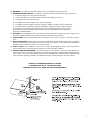
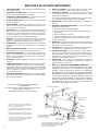
24. OUTDOOR ANTENNA GROUNDING—If an outside antenna or cable system is connected to the appliance, be
sure the antenna or cable system is grounded so as to provide some protection against voltage surged and built-up
static charges. Section 810 of the National electrical Code, ANSI/NFPA No. 70-1984, provides information with
respect to proper grounding electrodes, and requirements for the grounding electrode. See Figure below.
EXAMPLE OF ANTENNA GROUNDING ACCORDING
TO NATIONAL ELECTRICAL CODE INSTRUCTIONS
CONTAINED IN ARTICLE 810-”RADIO AND TELEVISION EQUIPMENT”
3

Terminal Board
Cover
Coaxial Cable
3-Wire
Rotator Cable
(1)
Yellow Wire
(2) Black Wire
(3) White Wire
Threaded Coax
Receptacle
Terminal Board
Cover Screws
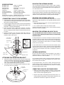
ANTENNA ORIENTATION
Because of the built-in rotator, antenna orientation is not critical. A
double-arrowhead is molded into the outer rim of the housing to
indicate the antenna’s center-of-rotation.
In a residential or fixed location, pointing the double arrowhead to-
ward the most often used TV station will reduce the amount of rota-
tion needed for best reception.
For non-fixed locations, such as RVs or boats, the antenna may be
installed with the double arrowheads facing in any direction. Opti-
mum TV reception may be obtained from any location or orienting
the antenna with its built-in rotator.
CONNECTING CABLE TO THE ANTENNA
1. Loosen the two screws on the terminal board cover on the bottom
of the antenna. This will expose a threaded coaxial receptacle and
three special screw-type terminals.
2. Screw the supplied coaxial cable’s lead-in connector onto the threaded
terminal. Caution: Be sure the center conductor of the cable is in the
hole of the F connector before tightening.
3. Fasten the yellow rotator control wire to terminal 1, the black
wire to terminal 2, and the white wire to terminal 3. Insert the
wire into clamping terminals between the terminal body and nut
as shown.
4. Replace the terminal cover so that the coaxial cable comes out
through the notch. Tighten the terminal cover screws. This will
clamp the rotator cable in place.
MOUNTING THE ANTENNA INDOORS
You can mount the antenna in an attic, closet or other out-of-the-
way indoor location. The antenna can be mounted on a vertical mast,
or on a short piece of mast suspended from a roof support by a 4-
inch wall-mount bracket .
You can also insert the three legs into the matching holes on the
underside of the antenna so that they angle outward to form a tripod
support. Then place the antenna on a shelf in a closet. Be sure the
antenna is not in a position where it could easily fall or be damaged.
MOUNTING THE ANTENNA OUTDOORS
For the best results, mount the antenna away from trees or other
obstructions. Higher frequencies are noticeably affected by these
obstructions.
1. Mount the antenna onto a mast. Secure it by tightening the hex
nuts evenly onto the U-bolt.
2. Use a wall-thru tube to neatly route cable thru walls.
Follow the instructions on pages 2 and 3 of this manual to properly
ground your antenna installation.
MOUNTING THE ANTENNA ON A BOAT OR RV
It is recommended that several locations be tried to find the
one that provides optimum performance before you permanently
install the antenna.
For best performance on vehicles and boats, the antenna should be
mounted as high as practical and as far away from metal objects as
possible. If the interior areas of the vehicle or boat are substantially
enclosed or surrounded by metal surfaces, an exterior mounting
location must be selected.
For RVs with metal roofs, the antenna should be mounted at least
six inches above the roof surface. For boats, best reception will be
obtained if the antenna is mounted above the boat’s highest deck
or cabin structure. RV/boat mount kits are available to do these
installations.
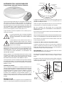
ATTACHING THE MOUNTING BRACKET
1. Attach the antenna mounting bracket to the four slotted metal
inserts on the bottom of the antenna using the four screws and
lockwashers provided. (Do not unscrew recessed metal in-
serts. They hold the internal motor in place.)
2. Insert the U-bolt to the mounting bracket using the two wash-
ers and hex nuts. Do not tighten.
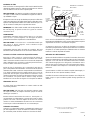
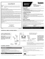
CONNECTING CABLES TO THE POWER SUPPLY
1. Attach the coaxial cable’s downlead connector to the threaded
coaxial terminal on the power supply unit, centering the inner con-
ductor in the hole before tightening the nut.
2. Slip the 3-wire rotator cable through the strain relief clamp. Con-
nect the yellow wire to Terminal 1, the black wire to Terminal 2, and
the white wire to Terminal 3. Tighten the connections.
SPECIFICATIONS
Bandpass VHF 54-88, 174-216 MHz
Bandpass UHF 470-806 MHz
FM trap (fixed) 88-108 MHz, 20 dB typical
VHF/UHF Gain up to 20dB
Impedance 75 Ohms, Unbalanced
Power Requirement 12VDC, 120 VAC, 60 Hz
Weatherproof housing UV-protected, filled copolymer
Mounting 1-1/2 inch round mast
Specifications are typical: Individual units may vary. Specifications
are subject to change and improvement without notice.
Mounting
Bracket
Metal
Inserts
U-Bolt
Screws and
Lockwashers
Washers and
Hex Nuts
Loosened
Terminal Screw
Tightened
Terminal Screw
2
13
4

CONNECTING TO A POWER SOURCE
Note: Do not plug your antenna’s power supply into an AC out-
let or DC power source until all electrical and antenna connec-
tions have been made. Doing so may short out the power supply’s
transformer and void your warranty. Caution: Do not use both
power sources at the same time.
• CONNECTING TO AN AC POWER SOURCE
Insert the power supply unit’s power cord into the nearest
120-volt AC outlet. The cord may be left plugged in at all
times since the amount of standby power used is very small,
about the same as that of an electric clock.
• CONNECTING TO A DC POWER SOURCE
Insert the DC power cord plug into the DC jack on the power
supply unit. Attach the red wire to the positive terminal and
the black wire to the negative terminal of the DC source used.
The DC power cord’s spade terminal ends can be removed if
your installation requires another type of connector. Note:
The DC power cord contains an inline protective fuse. For
continuous protection against fire hazard, replace fuse only
with the same type 0.8 ampere/250 volt rating.
ANTENNA OPERATION
With the TV set on and a station tuned in, rotate the antenna by
pressing the rocker switch located on the hand remote control.
Pressing the right side of the switch will turn the antenna in a
clockwise direction. Pressing the left side will turn it counter-
clockwise.
Although the actual antenna movement cannot be seen, the in-
dicator arrow on the control unit will light, showing the antenna’s
rotation. In about 30 seconds the antenna has made one full
turn and the End of Rotation light will come on. Observe the
picture while rotating the antenna first in one direction and then
the other, until the best picture quality is obtained. Releasing the
rocker switch stops rotation.
Antenna will not rotate, direction indi-
cator lamps do not light
Antenna will not rotate; at least one
direction indicator lamp lights properly
Antenna at end stop; will not rotate
Antenna rotating in wrong direction;
Left button indication flashes when
right button is pressed, etc.
Weak picture; no noticeable differ-
ence in picture when antenna is ro-
tated
3. Insert the 5-pin remote control unit plug into the matching 5-
pin receptacle on the power supply.
4. Attach the power supply mounting bracket to any conve-
nient flat surface and slide the power supply into place.
5. Connect the power supply’s coaxial cable’s output to your
TV’s coaxial cable input.
TV
TROUBLESHOOTING–
Refer any problems to your service technician.
SYMPTOM PROBABLE CAUSE
Do not service this product yourself, as opening or removing cov-
ers may expose you to dangerous voltage or other hazards. Refer
all servicing to qualified service personnel.
Power cord not plugged in, no
voltage to power supply, defec-
tive power supply, defective hand
remote control
3-wire rotator cable open or incor-
rectly connected; Defective motor;
Defective end stop switch
End stop switch defective
Power supply connections 1 and
3 are reversed
Defective amplifier; Open con-
nection between antenna and
amplifier; Open, shorted coaxial
lead-in cable; Shorted or open
amplifier coax wrap-around
cable inside antenna housing;
Defective power supply
MINI-STATE ANTENNA LIMITED WARRANTY
We warrant that if anything goes wrong with your ANTENNACRAFT Mini-
State Antenna within 90 days of purchase, and it is a manufacturing defect,
we will repair the unit or replace it at no cost. This warranty excludes all costs
arising from installation, removal, reinstallation or setup, transportation to
and from the dealer, and damage due to lightning, misuse or neglect. In addi-
tion, indirect, incidental, or consequential damages are not covered. Some
states do not allow the exclusion or limitation of indirect, incidental, or conse-
quential damages, so the above limitation or exclusion may not apply to you.
To obtain warranty service, please do the following:
1. Take the unit to the dealer from which it was purchased or any ANTEN-
NACRAFT Mini-State dealer.
2. Present your bill of sale or other evidence of the date on which the unit
was first purchased.
IT IS NECESSARY THAT YOU RETAIN YOUR BILL OF SALE OR PROOF OF
PURCHASE IN ORDER TO OBTAIN WARRANTY SERVICE.
OUT-OF-WARRANTY SERVICE
In the event your ANTENNACRAFT Mini-State 5MS9000 should fail after the
90 day limited warranty period, the ANTENNACRAFT Service Center will ei-
ther repair the non-functioning unit at a cost to be determined by the Service
Center and approved by you before the actual repair process is started, or
replace it with a remanufactured unit if available. The unit will be returned to
you C.O.D.
When returning for repair:
1. Call 319-758-8050 for a Return Authorization Number
2. Package the unit properly to prevent damage
3. Ship prepaid to:
ANTENNACRAFT,
1719 West Mount Pleasant Street
West Burlington, IA 52655
Please enclose your name, home phone number, daytime phone number, email
address, return ship address, proof of purchase and a description of the prob-
lem. You may be contacted by phone for more information about the antenna’s
malfunction. If the antenna is found not to be defective, there will be a fee of
$20 for servicing plus shipping costs.
4/05
www.antennacraft-tdp.com
Available Replacement Parts:
5MS9000 Hand Control
5MS9000 Power Supply
5MS9000 30’ Coaxial cable
5MS9000 RV Mounts (1 pair)
5
END OF
ROTATION
4
5
Coaxial
Cable
to TV
Coaxial
Cable
3-Wire Cable
1-Yellow
2-Black
3-White
Remote
Control
Power Supply Unit
Mounting
Bracket
Slot
5-Pin
Remote
Control
Plug
Rocker
Switch
120 VAC Plug
DC
Jack
To Antenna
Strain
Relief Clamp

DIRECTIVES DE SÉCURITÉ IMPORTANTES
1. LIRE LES DIRECTIVES – Lisez les directives de sécurité et d’utilisation
avant d’utiliser l’appareil.
2. CONSERVER LES DIRECTIVES – Conservez les directives de
sécurité et d’utilisation pour référence ultérieure.
3. RESPECTER LES MISES EN GARDE – Respectez toutes les mises
en garde sur l’appareil et dans la documentation.
4. SUIVRE LES DIRECTIVES – Suivez toutes les directives d’utilisation
et de fonctionnement.
5. EAU ET HUMIDITÉ – N’utilisez pas l’appareil près de l’eau - comme
près d’un évier, d’un lavabo, d’une baignoire ou d’une piscine ou en-
core, dans un sous-sol détrempé.
6. VENTILATION – Placez l’appareil là où il sera bien ventilé. Ainsi, ne le
placez pas sur un lit, un divan, un tapis ou une surface semblable où
les ouvertures pourraient devenir obstruées. Ne le placez pas dans
un meuble encastré ou une étagère où un courant d’air pourrait ne
pas être assuré à travers les ouvertures de ventilation.
7. CHALEUR – Placez l’appareil loin de sources de chaleur comme les
radiateurs, les bouches de chauffage, les cuisinières ou autres
appareils qui dégagent de la chaleur (comme un amplificateur)
8. ALIMENTATION – L’appareil devrait être branché à une alimentation
du type décrit dans les directives d’utilisation ou sur les étiquettes de
l’appareil.
9. MISE À LA TERRE OU POLARITÉ – Assurez-vous de ne pas contrer
les dispositifs de mise à la terre ou de polarité de l’appareil.
10. CORDON D’ALIMENTATION – Le cordon devrait être acheminé de
façon à ce qu’il ne soit pas écrasé ni pincé par des meubles ou des
articles, en prenant particulièrement soin des fiches, des prises et du
point de sortie de l’appareil.
11. NETTOYAGE – Nettoyez l’appareil conformément aux directives du
fabricant.
12. LIGNES HAUTE TENSION – N’installez jamais une antenne extérieure
à proximité des lignes haute tension ni des circuits d’éclairage ou
d’alimentation sur lesquels elle pourrait s’écraser. Lors de l’installation
d’une antenne extérieure, prenez particulièrement soin de ne pas
touches ces lignes ou circuits car tout contact avec ces lignes ou
circuits pourrait être mortel.
13. PÉRIODES D’INUTILISATION – Débranchez le cordon d’alimentation
de la prise de courant lorsque vous prévoyez ne pas utiliser l’appareil
pour une période prolongée.
EXEMPLE DE MISE À LA TERRE D’UNE ANTENNE
CONFORMÉMENT
AUX DIRECTIVES DU CODE NATIONAL DE L’ÉLECTRICITÉ
SE TROUVANT À L’ARTICLE 810 -
<<ÉQUIPMENT DE RADIO ET DE TÉLÉVISION>>
LIGNES HAUTE TENSION
LIGNES D’ENTRÉE
DE SERVICE
PINCE
DE TERRE
ISOLATEURS DE
SEPARATION
b
MÂT
FIL DE
L’ANTENNE
UNITÉ DE
DÉCHARGE
DE L’ANTENNE
c
AUX BORNES
D’ANTENNE
EXTÉRIEURE DE
L’APPAREIL
FIL DE
TERRE
a,b
ÉLECTRODE OPTIONNELLE DE MISE À LA TERRE
DE L’ANTENNE ENFONCEE 2.44 M (8PI) DANS LA
TERRE SILES CODES MUNICIPAUX L’EXIGENT.
VOIR NEC, SECTION 810-21 (f)
14. OBJETS ET LIQUIDES – Faites attention de ne pas insérer d’objets
pas les fentes et de ne pas renverser de liquides sur le boîtier.
15. CHARIOTS ET SUPPORTS – Si vous placez l’appareil sur un chariot
ou un support, assurez-vous qu’il s’agisse d’un chariot ou support
recommandé par le fabricant.
Un esemble chariot/appareil doit être déplacé avec soin. Arrêt soudain,
force excessive et surfaces inégales peuvent déséquiliber.
16. INSTALLATION – Installez l’appareil conformément aux directives du
fabricant.
17. DOMMAGES NÉCESSITANT UN SERVICE – Confiez la réparation à
une personne qualifée quand:
A. le cordon ou la fiche a été endommagée;
B. des objets sont tombés dans l’appareil ou de liquides renversés
dans le boîtier;
C. l’appareil a été exposé à la pluie;
D. l’appareil a été échappe ou son boîtier endommagé; ou quand
E. l’appareil ne semble pas bien fonctionner ou affiche une perte
marquée de rendement.
18. ENTRETIEN – L’utilisateur ne devrait effectuer aucun autre entretien
que celui recommandé dans les directives. Tout autre entretien devrait
être confié à une personne qualifée.
19. SURCHARGE – Ne surchargez pas les prises de courant ni les rallonges
car cela presénte un risque d’incendie ou de choc eléctrique.
20. PIÈCES DE RECHANGE – S’il faut remplacer des pièces, assurez-
vous que le technicien utilise les pièces de rechange spécifées par le
fabricant ou ayant les mêmes caractéristiques que les pièces d’origine.
Des pièces de rechange inadéquates peuvent présenter un risque
d’incendie, de choc eléctrique ou autres.
21. VÉRIFICATION – Après un service ou une réparation, demandez au
technicien d’effectuer une vérification de sécurité pour s’assurer que
l’appareil fonctionne correctement.
22.
MISE À LA TERRE D’UN ANTENNE EXTÉRIEURE – Si
l’appareil est branché à une antenne extérieure ou un câble,
assurez-vous que l’antenne ou le câble est mis à la terre pour
protéger contre les pointes de tension et les décharges
électrostatiques. La section 810 du Code national de l’électricité,
ANSI/NFPA n° 70-1984, fournit des renseignements concernant
la bonne mise à la terre du mât et des supports, la mise â la
terre du fil de l’unité de décharge, la grosseur des conducteurs
de terre, l’emplacement de l’unité de décharge, la connexion
des électrodes de terre et les exigeances concernant ces
électrodes. Voyez la figure ci-dessous.
ÉLECTRODE DE MISE À LA TERRE
DU SERVICE ÉLETRIQUE
(ex.: tuyau d’entrée d’eau)
TRESSE DE
MÉTALLISATION
ÉQUIPMENT
DE SERVICE
ÉLECTRIQUE
a Utilliser un fil de cuivre n # 10 (5.3mm
2
), d’aluminum n°
8 (8.4 mm
2
) ou d’acier couché de cuivre ou de bronze
n° 17 (1.0 mm
2
) comme fil de terre.
b Fixer le fil d’antenne et les fils de terre à la maison avec
de isolateurs de séparation a tous les 1.2 a 1.8m (4 à 5
pi).
c Installer l’unité de décharge de l’antenne aussi pres que
possible du point d’entrée du fil antenne dans la maison.
d Utiliser une tresse de métallisation en cuivre d’au moins
n° 6 AWG (13.3 mm
2
) ou l’équivalent si vous utilisez
une tige de terre séparée pour l’antenne.
Voir NEC, section 810-21(f)
PINCE
DE TERRE
FIL DE TERRE
a,b
6

L’antenne électronique Mini-State est un dispositif conçu pour être
utilisé dans les véhicules récréatifs, les bateaux ou à la maison. Il
se compose d’une antenne unidirectionnelle, d’un amplificateur
transistorisé spécial et d’un mécanisme électrique de rotation; tout
cela est emboîté dans un dôme en plastique breveté résistant aux
intempéries. La télécommande s’alimente sout d’une source C.C.
de 12 V. (masse négative), soit de secteur (120 V.C.A.).
Le gain minimal de l’antenne amplifiée est de 20 dB tant pour les
canaux UHF que THF.
Le point d’exclamation dans un triangle équilatéral
avertit l’usager de la présence, dans le manuel, de
directives importantes concernant l’emploi et
l’entretien.
L’éclair terminé par une pointe de flèche, dans un
triangle équilatéral avertit l’usager d’une <<tension
dangeruse>> non protégée dans l’enceinte et qu’elle
peut être d’une intensité suffisante pour présenter un
risque de choc électrique.
AFIN DE RÉDUIRE LE RISQUE DE CHOC ÉLECTRIQUE, NE PAS
ENLEVER LE COUVERCLE (NI LE DOS) DE L’ANTENNE OU DE
L’ALIMENTATION. IL NE S’Y TROUVE AUCUNE PIÈCE QUE
L’UTILISATEUR PUISSE RÉPARER, SE RÉFÉRER À UN
TECHNICIEN QUALIFIÉ.
MISE EN GARDE: Lors de l’installation,éviter tout risque de contact
accidentel entre l’antenne et son mât et une ligne de tension. LE
CONTACT AVEC UNE LIGNE DE TENSION RISQUE DE CAUSER
DE SÉRIEUSES BLESSURES VOIRE MÊME LA MORT.
Comme protection contre l’accumulation de charges électrostatiques
lors d’orages électriques, on recommande de bien mettre à la terre
le mât de l’antenne à l’aide d’un fil de cuivre #10 AWG ou d’aluminum
#8 AWG au moins.
Installation de l’antenne
Sur les véhicules et les bateaux, la meilleure performance sera
assurée en montant l’antenne au point le plus haut et aussi loin que
possible d’objets métalliques. Si l’intérieur de véhicule ou du bateau
est relativement fermé ou entouré de surfaces métalliques, on devrait
installer l’antenne à l’extérieur. Dans le cas d’un véhicule de
récréation avec toit métallique, on devrait installer l’antenne à au
moins six pouces au-dessus de la toiture. Sur un bateau, installer
l’antenne sur le plus haut pont ou sur la cabine donnera les meilleurs
résultats.
Montage sur mât
L’antenne est vendue avec un support en acier inoxydable pour la
fixation à un mât d’antenne de télévision standard (non inclus). Fixer
ANTENNE DE TELE UHF/VHF AMPLIFEE
Usage menager & Recreatif, Interieur et Exterieur
le support sous le boîtier de l’antenne à l’aide des quatre (4) vis et
rondelles de blocage fournies. Les vis se taraudent dans les
plaquettes métalliques fendues.
Incliner le support comme illustré de façon à ce que ses mâchoires
se trouvent face au couvercle de la plaque de connexion.
NE PAS TENTER DE DÉVISSER LES PLAQUETTES
MÉTALLIQUES CAR ELLES RETIENNENT LE MÉCANISME IN-
TERNE EN PLACE.
Fixer l’antenne et le support au mât à l’aide de la bride filetée et des
deux (2) écrous fournis.
NE PAS TENTER DE DÉVISSER LES PLAQUETTES MÉTALLIQUES
CAR ELLES RETIENNENT LE MÉCANISME INTERNE EN PLACE.
Fixer l’antenne et le support au mât à l’aide de l’étrier et des deux
écrous hexagonaux fournis.
Connection du câble coaxial et du dispositif de rotation
Commencer par desserrer le deux vis du couvercle de connexion et
enlever ce dernier par le dessous de dôme. Ceci dévoile une prise
filetée pour câble coaxial et trois bornes à vis. Visser fermement le
connecteur du câble coaxial sur la prise filetée.
MISE EN GARDE: Bien centrer le fil conducteur central avec l’orifice
de la prise avant de visser le connecteur.
Brancher le fil de commande jaune à la borne 1, le fil noir à la borne 2
et le fil blanc à la borne 3. Passer le fil dans les agrafes, comme
illustré.
Remettre le couvercle de connexion en passant le câble coaxial dans
la fente sur le côte. Resserrer les vis du couvercle. Ceci fixera le
câble du dispositif de rotation.
7
Noir Fil
Desserrer la vis
de la borne
Insérer le fil -
Resserrer la vis
Couvercle
Cable a 3 fils
du moteur
de rotation
Jaune
Fil
Blanc Fil
Connecteur Coaxial
Cable
Coaxial
Monter le Crochet
U-Boulon
Vis et Serrure
Rondelles
Rondelles
Écrous Hexagonaux
Mât Serre-joint
le Metal Insère

Installation du câble
Fixer au mât avec un ruban gommé le câble coaxial combiné au fil du
dispositif de rotation. Amener le câble jusqu’au téléviseur en le fixant
avec des attaches à tous les trous ou quatre pieds.
MISE EN GARDE: Les attaches ou agrafes ne doivent pas presser
ou couper le câble coaxial. Une déformation exagérée du câble ris-
que d’affaiblir le signal.
Il faut percer un trou de 1/2 po de diamètre pour passer le câble dans
un mur ou un plancher. Pour faciliter le passage du câble dans le trou,
replier le fil du dispositif de rotation sur le câble coaxial de façon à ce
que le connecteur coaxial passe en premier dans le trou.
REMARQUE: Si le câble coaxial combiné au fil du dispositif de rota-
tion est trop long, on peut le raccourcir et y poser un nouveau
connecteur <<F>>.
ALIMENTATION
L’alimentation fonctionne soit du secteur (120 V.C.A.), soit d’une
source 12 V.C.C. (masse négative). Ces deux types de tension
peuvent être branchées séparément ou simultanément.
MISE EN GARDE: Le circuit 12 V.C.C. ne doit être branché qu’à
une source à masse négative. Faire autrement risque
d’endommager le dispositif.
L’alimentation fait aussi office de boîtier de connexion. Elle peut
être fixée au dos du téléviseur ou sur une surface derrière celui-ci.
Connexion du câble coaxial et du dispositif de rotation
Brancher le câble coaxial au connecteur fileté du boîtier de
l’alimentation en s’assurant de centrer le fil interne avec l’orifice
dans le connecteur avant de serrer l’écrou. Passer le fil du dispositif
dans le détendeur et en connecter le conducteur jaune à la borne 1,
le noir à la borne 2 et le blanc à la borne 3.
Insérer la fiche à cinq broches de la commande à main dans la
prise correspondante de l’alimentation. Connecter les fils du diviseur
de bandes UHF et THF aux bornes correspondantes sur le téléviseur.
Si ce dernier est doté d’une prise coaxiale THF et qu’il n’y a pas de
postes UHF dans la région, on peut dévisser le connecteur <<F>>
du diviseur de bandes et le brancher directement à la prise coaxiale
sur le téléviseur. Ceci pourra aider à réduire la neige et autres
interférences à l’écran dans les régions où la réception est difficile.
Alimentation 12 V.C.C.
Le cordon fourni pour l’alimentation en courant continu est doté
d’un fusible protecteur.
MISE EN GARDE: Afin d’assurer une protection soutenue contre
les risques d’incendie, ne remplacer le fusible que par un autre de
même type: 0,8 A/250 V.
Brancher la fiche à deux broches du cordon C.C. dans la prise C.C.
correspondante sur l’alimentation. Connecter le fil rouge à la borne
positive et le fil noir à la borne négative de la source en courant
continu. Le cordon d’alimentation est fourni avec des connecteurs
à fourche qui s’enlèvent facilement s’ils ne conviennent pas.
Orientation de l’antenne
Comme il y a un dispositif de rotation, l’orientation de l’antenne n’est
pas très importante. Le centre de rotation de l’antenne est indiqué
par une double pointe de flèche moulée sur la bordure du dôme.
Dans une aire résidentielle fix, pointer cent indicateur vers le
transmetteur de télédiffusion le plus souvent utilisé réduira l’ampleur
d’ajustement nécessaire à une meilleure réception.
Si l’antenne se trouve sur un véhicle de récréation ou un bateau,
l’indicateur peut pointer dans n’importe quelle direciton. La meilleure
réception en un endroit quelconque s’obtiendra alors en orientant
l’antenne à l’aide du dispositif de rotation.
Utilisation de la télécommande
Après avoir allumé le téléviseur et syntonisé une station, faire tourner
l’antenne en manipulant le commutateur à bascule de la commande.
Appuyser sur le côte droit du commutateur fait tourner l’antenne
vers la droite et appuyer sur le côté gauche, la fait tourner vers la
gauche. Bien qu’on ne puisse pas voir le mouvement de l’antenne,
le sens de rotation sera indiqué sur la commande par une flèche
lumineuse.
Quand l’antenne a réalisé une rotation complète (360 degrés), le
témoin de fin de course (End of Rotation) s’allume.
Surveiller l’écran tout en faisant tourner l’antenne d’un côté puis de
l’autre, jusqu’à ce que la meilleure qualité d’image possible soit
obtenue.
8
006393007
© 2005 ANTENNACRAFT
Covered under one or more of the following U.S. Patents:
227,785; 3,721,990; 3,761,333; 3,909,691
END OF
ROTATION
4
5
Le Câble
Coaxial
et Terminal
enfile
Vers
l’antenne
Jaune1, Noir 2, Blanc 3
Cable à 3 Fils
le Bouchon de
5 Épingles
de Télécommande
Corde d’alimentation
120 VCA
12VCC
Alimenter les Connexions
de Provision
TV
Le télé
coâxial
de cable
Télécommande
Fente du
Support
-
 1
1
-
 2
2
-
 3
3
-
 4
4
-
 5
5
-
 6
6
-
 7
7
-
 8
8


AntennaCraft Mini State 5MS9000 Manuel utilisateur
- Taper
- Manuel utilisateur
dans d''autres langues
Autres documents
-
 HDView360 Mini-State HDMS9100 Manuel utilisateur
-
Sylvania C6615LE Manuel utilisateur
-
Channel Master Digital Advantage 45 Manuel utilisateur
-
Philips SDV2940 Manuel utilisateur
-
Funai F20LCTE Manuel utilisateur
-
Durabrand RSDCT2704R Le manuel du propriétaire
-
-
 Symphonic CST204FE Manuel utilisateur
-
Hitachi Ultravision C55M6 Le manuel du propriétaire
-
CMP Econ Union Mode d'emploi

