Raychem CS-150-xx-PI Guide d'installation
- Taper
- Guide d'installation

CS-150-xx-PI
Connection and splice kit for polymer
insulated (PI) series heating cable
Anschluss- und verbindungsgarnitur für
polymerisolierte heizleitungen (PI)
Kit de connexion et de jonction pour
câble serie à isolation polymère (PI)
Aansluitset en verbindingsmof voor
kunststof seriële verwarmingskabel
Набор для соединения/сращивания
греющих кабелей с полимерной изоляцией

2 | nVent.com/RAYCHEM
ENGLISH
Installation instructions for cold lead connection and splice kit for use with
Raychem Polymer insulated (PI) series heating cables.
WARNING: Only use original crimps and crimp tool as specified in the
instructions. In addition to these instructions, the guidelines for installing
series heating systems must be followed.
DEUTSCH
Montageanleitung für Kaltleiter- Anschluß- und
Verbindungsgarnitur. Verwendbar für alle Polymer-isolierten (PI) seriellen
Heizleitungen von Raychem.
ACHTUNG: Verwenden Sie nur die Original - Quetschverbinder und
Preßwerkzeuge, die in der Montageanleitung spezifiziert sind. Zusätzlich zu
dieser Anleitung muß die Montageanleitung für die Montage des gesamten
PI-Begleitheizsystemes beachtet werden.
FRANÇAIS
Instructions d’installation pour kit de raccordement avec sortie froide et pour
jonction en ligne. Kit à utiliser avec des câbles chauffants série à isolation
polymère (PI) de Raychem.
ATTENTION : N’utiliser que les cosses et les pinces à sertir
d’origine comme spécifiées dans la notice d’installation.
En plus des instructions qui suivent, les instructions d’installation des câbles
chauffants à isolation polymère doivent aussi être appliquées.
NEDERLANDS
Installatie instructies voor koudeinde en verbindingsmof voor gebruik met
kunststof geïsoleerde seriële verwarmingskabels van Raychem.
Waarschuwing: Gebruik alleen originele verbinders en krimptang zoals
gespecificeerd in de instructies. Daarbij dienen de richtlijnen voor installatie
van seriële verwarmingskabels te worden opgevolgd.
РУССКИЙ
Инструкция по монтажу набора для сращивания греющих кабелей
или подсоединения холодного ввода к греющему кабелю. Набор
предназначен для использования с греющими кабелями Raychem с
полимерной изоляцией.
ПРЕДУПРЕЖДЕНИЕ: Необходимо использовать только
оригинальные соединительные гильзы и обжимной инструмент,
которые указаны в инструкции. Помимо настоящей инструкции
необходимо также следовать инструкции по монтажу систем
обогрева с последовательными греющими кабелями.


4 | nVent.com/RAYCHEM
ENGLISH
CS-150-xx-PI:
PTB 08 ATEX
1101 U
II 2G Ex 60079-30-1
IIC Gb
II 2D Ex 60079-30-1
IIIC Db
IECEx PTB
08. 0050U
Ex 60079-30-1 IIC Gb
Ex 60079-30-1 IIIC Db
XPI-F, XPI and XPI-S Bulk Cable Approval
Baseefa15A-
TEX0158U
II 2 G Ex 60079-30-1
IIC Gb
II 2 D Ex 60079-30-1 IIIC
Db
IECEx BAS
15.0105U
Ex 60079-30-1 IIC Gb
Ex 60079-30-1 IIIC Db
XPI-F, XPI and XPI-S System Approval
PTB 08 ATEX
1102X
II 2 G Ex eb 60079-30-1
IIC T2 …T6 Gb
II 2 D Ex tb 60079-30-1
IIIC T260 …T90 ˚C Db
IECEx PTB
08.0051X
Ex eb 60079-30-1 IIC T2 …
T6 Gb
Ex tb 60079-30-1 IIIC T260
…T90 ˚C Db
TC RU C-BE.ИМ43.В.01854
Ex e II Gb U
Ex tb IIIC Db U
Ta –55°C…+200°C IP65
ООО “ТехИмпорт”
Special conditions for safe use:
1. The temperature class is to be
determined in the EC-type test
certificate for the system.
2. The splice unit has to be fixed
installed. To avoid damage by pulling,
the heating and cold lead cables have
to be fixed adjacent to the splice.
The operating instruction of the
manufacturer has to be followed.
3. The maximum withstand temperature
for the XPI- and XPI-S- cable is
+260˚C, for the XPI-F-cable +90˚C
and for the CS-150-xx-PI Cold Applied
Connection & Splice Kits is +200˚C.
4. The maximum supply voltage for the
XPI-cable is shown in the component
description.
5. The minimum installation
temperature is –70˚C for the XPI- and
XPI-S-cable, –60˚C for the XPI-F-cable
and –50˚C for the CS-150-xx-PI Cold
Applied Connection & Splice Kits.
6. The minimum cable spacing must not
be less than 20mm.
7. The minimum bend radius is 2.5x the
cable diameter for cables less than
or equal to 6mm in diameter or the
minimum bend radius is 6x the cable
diameter for cables greater than 6mm
in diameter.
8. The XPI- or XPI-F-cable is for use in
areas with low risk of mechanical
damage, therefore appropriate
installation consideration shall be
taken. The XPI-S-cable is for use in
areas with normal risk of mechanical
damage.
9. The CS-150-xx-PI Cold Applied
Connection & Splice Kits shall be
secured when installed. To avoid
tensile stress, heating or installation
cables shall be fixed in their position
in the immediate vicinity of the
connection splice.
10. CS-150-xx-PI is for a one time
installation only, and the component
cannot be modified once it is
installed.
Rated insulation voltage
XPI-F 300/500 Vac (Uo / U)
XPI and XPI-S 450/750 Vac (Uo / U)
Max allowed operating current
(continuous.) depending on cold lead
cable.
Tabel I: Cold lead selection
cross current nominal order
section rating resistance reference
[mm²] [ A ] [Ω/km @ 20°C]
CS-150-2.5-PI 2.5 32 7 XPI-7 or
XPI-F 7
4 42 4.4 XPI-4.4 or
XPI-F 4.4
CS-150-6-PI
6 54 2.9 XPI-2.9 or
XPI-F 2.9
10 73 1.8 XPI-1.8 or
XPI-F 1.8
CS-150-25-PI 16 98 1.1 XPI-1.1
25 129 0.8 XPI-0.8
* Alternatively XPI-S cold leads can be
used as well.
When used as a splice, the max. allowed
current is to be determined by the cable
type and parameters like specific power
and exposure temperature.
Voltage/Insulation resistance test is
to be performed after installation and
every change. Insulation test voltage 1,2
x (2U+1000 V) Vdc (U nominal voltage
between live and neutral). Apply test
voltage between conductor and braid.
Maximum use temperature
XPI & XPI-S
200°C (260°C intermittent)
XPI-F
90°C (100°C intermittent)
Ambient temperature range.
–50°C / +40°C

nVent.com/RAYCHEM | 5
DEUTSCH
CS-150-xx-PI:
PTB 08 ATEX
1101 U
II 2G Ex 60079-30-1
IIC Gb
II 2D Ex 60079-30-1
IIIC Db
IECEx PTB
08. 0050U
Ex 60079-30-1 IIC Gb
Ex 60079-30-1 IIIC Db
XPI-F, XPI und XPI-S Einzelzulassung
Baseefa15A-
TEX0158U
II 2 G Ex 60079-30-1
IIC Gb
II 2 D Ex 60079-30-1 IIIC
Db
IECEx BAS
15.0105U
Ex 60079-30-1 IIC Gb
Ex 60079-30-1 IIIC Db
XPI-F, XPI und XPI-S Systemzulassung
PTB 08 ATEX
1102X
II 2 G Ex eb 60079-30-1
IIC T2 …T6 Gb
II 2 D Ex tb 60079-30-1
IIIC T260 …T90 ˚C Db
IECEx PTB
08.0051X
Ex eb 60079-30-1 IIC T2 …
T6 Gb
Ex tb 60079-30-1 IIIC T260
…T90 ˚C Db
TC RU C-BE.ИМ43.В.01854
Ex e II Gb U
Ex tb IIIC Db U
Ta –55°C…+200°C IP65
ООО “ТехИмпорт”
Besondere Bedingungen für den sicheren
Einsatz:
1. Die Temperaturklasse ist in der
EG-Baumuster- prüfbescheinigung für
das Heizsystem fest-zulegen.
2. Die Verbindungsmuffe muss
befestigt werden. Zur Vermeidung
von Zugbeanspruchung sind die Heiz-
bzw. Kaltleitungen unmittelbar in der
Nähe der Muffe zu fixieren.
3. Die max. Einsatztemperatur für
XPI- und XPI-S Heizkabel beträgt
260°C, für XPI-F max. 90°C
und für die Kaltanschluss- und
Verbindungsgarnitur max. 200°C.
4. Die max. Versorgungsspannung für
XPI Heizkabel ist aus der technischen
Beschreibung des jeweiligen
Datenblattes zu entnehmen.
5. Die minimale Installationstemperatur
beträgt für:
XPI- und XPI-S: –70°C
XPI-F: –60°C
CS-150-xx-PI (Kalltanschluss- und
Verbindungsgranitur): –50°C
6. Der minimale Verlegeabstand
zwischen den Heizkabeln von 20mm
darf nicht unterschritten werden.
7. Der minimale Biegeradius beträgt:
• 2,5x Kabeldurchmesser für
Kabeldurchmesser bis 6mm und
• 6x Kabeldurchmesser für
Kabeldurchmesser größer ab 6mm.
8. Die XPI- oder XPI-F-Heizkabel sind
für den Einsatz in Bereichen mit
einem Risiko an mechanischer
Beschädigung vorgesehen. Es sollte
auf eine fachgerechte Installation
geachtet werden. Das XPI-S
Heizkabel ist für den Einsatz in
Bereichen mit einem normalen Risiko
an mechanischer Beschädigung
vorgesehen.
9. Bei der Installation der CS-150-
xx -PI Kaltanschluss- und
Verbindungsgarnitur ist auf eine
sichere Befestigung zu achten. Zur
Vermeidung von Schäden durch
Mateialausdehnungen sollte die
Befestigung der angeschlossenen
Heizkabel unmittelbar neben der
Verbindungsgarnitur erfolgen.
10. CS-150-xx-PI ist nur für eine
einmalige Installation vorgesehen,
und die Komponente kann nach der
Installation nicht mehr geändert
werden.
Bemessungsisolationsspannung
XPI-F 300/500 Vac (Uo / U)
XPI and XPI-S 450/750 Vac (Uo / U)
Max. zulässiger Dauer-Strom:
(hängt ab vom Kaltleiter).
ATTENTION: to avoid danger of
electrical shock or fire, the product must
be installed in accordance with these
instructions.
Ingress of moisture has to be avoided
before and during installation.
RCD’s are required for all heating circuits.
Read instructions completely before
starting installation. This product does
not require maintenance. Damaged units
shall be replaced. Do not use other parts
or duct tape, metal bandings, tie wire or
vinyl electrical tape. Avoid eye contact
with the silicone compound.
Respect the safety data sheet.
Refer to “Installation, Maintenance and
Operation Manual Polymer Insulated (PI)
Series Constant Wattage Heating Cable
Systems” De-energize circuits before
installation or servicing.Keep ends of trace
Heaters and kits components dry before
and during installation.Persons involved in
the installation and testing of electric trace
heating systems shall be suitably trained in
all special techniques required. Installation
shall be carried out under the supervision
of a qualified person.

FRANÇAIS
CS-150-xx-PI:
PTB 08 ATEX
1101 U
II 2G Ex 60079-30-1
IIC Gb
II 2D Ex 60079-30-1
IIIC Db
IECEx PTB
08. 0050U
Ex 60079-30-1 IIC Gb
Ex 60079-30-1 IIIC Db
Agrément des câbles en vrac XPI-F, XPI
et XPI-S
Baseefa15A-
TEX0158U
II 2 G Ex 60079-30-1
IIC Gb
II 2 D Ex 60079-30-1 IIIC
Db
IECEx BAS
15.0105U
Ex 60079-30-1 IIC Gb
Ex 60079-30-1 IIIC Db
XPI-F, XPI and XPI-S System Approval
PTB 08 ATEX
1102X
II 2 G Ex eb 60079-30-1
IIC T2 …T6 Gb
II 2 D Ex tb 60079-30-1
IIIC T260 …T90 ˚C Db
IECEx PTB
08.0051X
Ex eb 60079-30-1 IIC T2 …
T6 Gb
Ex tb 60079-30-1 IIIC T260
…T90 ˚C Db
TC RU C-BE.ИМ43.В.01854
Ex e II Gb U
Ex tb IIIC Db U
Ta –55°C…+200°C IP65
ООО “ТехИмпорт”
Conditions spéciales pour une utilisation
sûre :
1. La classe de température doit être
déterminée en fonction du certificat
CE de type pour le système.
2. Le kit de jonction doit être fixé
sur le système. Pour éviter toute
détérioration par arrachage, le
câble chauffant et les sorties
froides doivent être fixées proche
de la jonction. Les instructions
d’installation du fabriquant doivent
être appliquées.
Tabelle I: Kaltleiter-Auswahl
Quer- Bemess.- Nenn- Bestell-
schnitt strom widerstand nummer
[mm²] [ A ] [Ω/km @ 20°C]
CS-150-2.5-PI 2.5 32 7
XPI-7 oder
XPI-F 7
4 42 4.4 XPI-4.4 oder
XPI-F 4.4
CS-150-6-PI
6 54 2.9 XPI-2.9 oder
PI-F 2.9
10 73 1.8 XPI-1.8 oder
XPI-F 1.8
CS-150-25-PI
16 98 1.1 XPI-1.1
25 129 0.8 XPI-0.8
* Alternativ können auch XPI-S-Kaltleiter
verwendet werden.
Bei Verwendung als Heizleitungs-
Verbinder wird der max. zulässige Strom
von der Heizleitungstype und Parametern
wie Heizleistung und Einsatztemperatur
bestimmt.
Nach erfolgter Montage und jeder
Änderung muss eine Spannungsprüfung
durchgeführt werden.
Isolationsprüfspannung 1,2 x (2U+1000 V)
V DC (U = Nennspannung zwischen Phase
und Nullleiter).
Prüfspannung zwischen Leiter und
Schutzgeflecht anlegen.
Max. Einsatztemperatur:
XPI & XPI-S
200°C (260°C kurzzeitig)
XPI-F
90°C (100°C kurzzeitig)
Umgebungstemperatur:
–50°C/ +40°C
ACHTUNG: Zur Vermeidung von
elektrischem Schlag und Bränden
muß dieses Produkt vorschriftsmäßig
montiert werden. Das Eindringen von
Feuchtigkeit muß vor und während
der Montage vermieden werden. Alle
Heizkreise müssen über FI-Schutzschalter
abgesichert werden. Lesen Sie die
Montage anleitung sorgfältig und
vollständig, bevor Sie mit der
Montage beginnen. Wartung ist nicht
erforderlich. Beschädigte Teile müssen
ausgetauscht werden. Keine anderen
Teile oder Isolierband, Metallbänder,
Kabelbinder oder Isolierband aus Vinyl
verwenden. Vermeiden Sie Augenkontakt
mit der Silikon-Vergußmasse. Beachten
Sie das Sicherheits datenblatt.
Beachten Sie bitte die Hinweise in der
“Installations- und Wartungsanleitung für
Polymerisolierte Widerstandsheizleitungen
(PI) Systeme” bevor Sie mit den
Arbeiten und oder Installationen an
Begleitheizungssystemen beginnen.
Halten Sie die Enden der Heizkabel und
deren Komponenten vor und während der
Installation trocken. Personen, welche
mit der Installation und dem Prüfen an
Begleitheizungssystemen beauftragt
sind, sollten ausreichend in allen dafür
erforderlichen und vorgegebenen Bereichen
befähigt und geschult sein. Die Installation
sollte unter Aufsicht einer ausgebildeten
Fachkraft erfolgen.
6 | nVent.com/RAYCHEM

3. La température maximale d’exposition
pour le câble XPI et XPI-S est de
+260˚C, pour le câble XPI-F de +90˚C
et pour le kit de connection et de
jonction à froid CS-150-xx-PI est de
+200˚C.
4. La tension d’alimentation maximale
pour le câble XPI est indiquée dans la
description du composant.
5. La température minimale
d’installation est de –70˚C pour le
câble XPI et XPI-S,
–60˚C pour le câble XPI-F et –50˚C
pour le kit de connection et de
jonction à froid CS-150-xx-PI.
6. L’espacement minimal des câbles ne
peut pas être inférieur à 20 mm.
7.
Le rayon de courbure minimal est de
2,5x le diamètre du câble pour les
câbles d’un diamètre inférieur ou égal
à 6mm, et 6x le diamètre du câble pour
les câbles d’un diamètre supérieur à
6mm.
8. Le câble XPI ou XPI-F est destiné à
être utilisé dans des zones présentant
un faible risque de dommages
mécaniques, c’est pourquoi il convient
de prendre quelques précautions
lors de l’installation. Le câble XPI-S
est destiné à être utilisé dans des
zones présentant un risque normal de
dommages mécaniques.
9. Les kit de connection et de jonction à
froid CS-150-xx-PI doivent être fixés
lors de l’installation. Pour éviter les
forces de traction sur les connecteurs,
les câbles de chauffage ou
d’installation doivent être fixés dans
leur position à proximité immédiate
de la jonction.
10. CS-150-xx-PI est destiné à une
installation unique, et le composant
ne peut pas être modifié une fois qu’il
est installé.
Tension d’isolement :
XPI-F 300/500 Vac (Uo / U)
XPI and XPI-S 450/750 Vac (Uo / U)
Courant maximum admis : (en continu)
suivant le câble de sortie froide
Tabelle I: Sélection de câble de sortie froide
Section Calibre Résistance Réference
Courant nominale Commande
[mm²] [ A ] [Ω/km @ 20°C]
CS-150-2.5-PI 2.5 32 7 XPI-7 ou
XPI-F 7
4 42 4.4 XPI-4.4 ou
XPI-F 4.4
CS-150-6-PI
6 54 2.9 XPI-2.9 ou
XPI-F 2.9
10 73 1.8 XPI-1.8 ou
XPI-F 1.8
CS-150-25-PI 16 98 1.1 XPI-1.1
25 129 0.8 XPI-0.8
* Alternativement un conduit XPI-S
froide peut être utilisée.
Quand le kit est utilisé en jonction en
ligne, le courant maximum, la puissance
et la température d’exposition snt
déterminés par le type de câble chauffant
utilisé.
Le test de d’isolement doit être réalisé
après installation et après chaque
modification. La tension de test est 1,2x
(2U + 1000 V)
(U est la tension nominale entre la phase
et le neutre). Le test s’applique entre les
conducteurs chauffants et la tresse.
Température maximale de service
XPI 7 XPI-S
200°C (260°C intermittent)
XPI-F
90°C (100°C intermittent)
Plage de température ambiante
–50°C / +40°C
ATTENTION: de façon à éviter tout
danger électrique par contact ou feu,
les produits doivent être installés en
conformité avec ces instructions.
La pénétration d’humidité doit être évitée
avant et pendant l’installation.
Les protections différentielles sont
requises pour tous les circuits.
Lire entièrement ces instructions avant
le début de tous travaux. Ce produit ne
requiert pas de maintenance. Les pièces
endommagées doivent être remplacées.
Ne pas utiliser d’autres pièces que celles
fournies dans le kit (notamment ruban
adhésif ou colliers métaliques)
Eviter tout contact du composé silicone
avec les yeux. Respecter les informations
de la fiche de sécurité.
Se référer au “Manuel d’installation,
d’entretien et d’utilisation des systèmes de
câbles chauffants à puissance constante
à isolation polymère (PI)”. Mettre les
circuits hors tension avant l’installation
ou l’entretien. Garder les extrémités des
câbles chauffants et les composants des
kits au sec avant et pendant l’installation.
Les personnes participant à l’installation
et à l’essai des systèmes de traçage
électrique doivent être convenablement
formées à toutes les techniques spéciales
requises. L’installation doit être effectuée
sous la supervision d’une personne
qualifiée.

8 | nVent.com/RAYCHEM
NEDERLANDS
CS-150-xx-PI:
PTB 08 ATEX
1101 U
II 2G Ex 60079-30-1
IIC Gb
II 2D Ex 60079-30-1
IIIC Db
IECEx PTB
08. 0050U
Ex 60079-30-1 IIC Gb
Ex 60079-30-1 IIIC Db
XPI-F, XPI en XPI-S Bulk Kabelgoedkeuring
Baseefa15A-
TEX0158U
II 2 G Ex 60079-30-1
IIC Gb
II 2 D Ex 60079-30-1 IIIC
Db
IECEx BAS
15.0105U
Ex 60079-30-1 IIC Gb
Ex 60079-30-1 IIIC Db
XPI-F, XPI en XPI-S Systeemgoedkeuring
PTB 08 ATEX
1102X
II 2 G Ex eb 60079-30-1
IIC T2 …T6 Gb
II 2 D Ex tb 60079-30-1
IIIC T260 …T90 ˚C Db
IECEx PTB
08.0051X
Ex eb 60079-30-1 IIC T2 …
T6 Gb
Ex tb 60079-30-1 IIIC T260
…T90 ˚C Db
TC RU C-BE.ИМ43.В.01854
Ex e II Gb U
Ex tb IIIC Db U
Ta –55°C…+200°C IP65
ООО “ТехИмпорт”
Speciale condities voor veilig gebruik:
1. De temperatuurklasse wordt bepaald
door het CE-certificaat voor het
systeem.
2. De mof wordt vastgemaakt (op de
buis). Om schade te voorkomen bij
het trekken worden de verwarmings-
en koudeinde kabels vastgemaakt
vlak naast de mof. Volg de richtlijnen
van de fabricant.
3. De maximale weerstandtemperatuur
voor de XPI- en XPI-S-kabel is +260˚C,
voor de XPI-F-kabel +90˚C en voor de
CS-150-xx-PI C koudeinde aansluitset
en verbindingsmof +200˚C.
4. De maximale voedingsspanning voor
de XPI-kabel staat vermeld in de
componentbeschrijving.
5. De minimale installatietemperatuur
is –70˚C voor de XPI- en XPI-S-kabel,
–60˚C voor de XPI-F-kabel en –50˚C
voor de CS-150-xx-PI koudeinde
aansluitset en verbindingsmof.
6. De minimale kabelafstand mag niet
kleiner zijn dan 20mm.
7. De minimale buigradius is 2,5x de
kabeldiameter voor kabels met een
diameter van minder dan of gelijk aan
6 mm, of de minimale buigradius is 6x
de kabeldiameter voor kabels met een
diameter van meer dan 6 mm.
8. De XPI- of XPI-F-kabel is voor gebruik
in zones met een laag risico op
mechanische schade, daarom moet
er rekening worden gehouden met
de juiste installatie. De XPI-S-kabel
is voor gebruik in zones met een
normaal risico op mechanische
schade.
9. De CS-150-xx-PI koudeinde
aansluitset en verbindingsmof dienen
bij installatie te worden beveiligd. Om
trekspanning te voorkomen, moeten
de verwarmings- of installatiekabels
worden bevestigd in hun positie
in de directe nabijheid van de
verbindingslink.
10. CS-150-xx-PI dient enkel voor
een eenmalige installatie, en
de component kan niet worden
aangepast eens geïnstalleerd.
Toegestane spanningen
XPI-F 300/500 Vac (Uo / U)
XPI and XPI-S 450/750 Vac (Uo / U)
Max. toelaatbare stroom (continu)
afhankelijk van type koudeinde.
Tabel I: Selectie van koudeinde kabel
Door- Stroom- Nominale Bestel-
snede sterkte weerstand code
[mm²] [ A ] [Ω/km @ 20°C]
CS-150-2.5-PI 2.5 32 7 XPI-7 of
XPI-F 7
4 42 4.4 XPI-4.4 of
XPI-F 4.4
CS-150-6-PI
6 54 2.9 XPI-2.9 of
XPI-F 2.9
10 73 1.8 XPI-1.8 of
XPI-F 1.8
CS-150-25-PI 16 98 1.1 XPI-1.1
25 129 0.8 XPI-0.8
* Er mogen ook XPI-S koudeindes
gebruikt worden.
Wanneer het product wordt toegepast
als verbindingsmof worden maximale
stroom toegestane temperatuur en
vermogen bepaald door de toepaste
verwarmingskabel.
Spanning / weerstandstesten moeten
worden uitgevoerd na iedere installatie of
verandering in de installatie.
Testspanning isolatie 1,2 x (2U + 1000 V)
Vdc (U nominale spanning tussen fase
en nulleider). Testspanning meten tussen
geleider en aardingsvlechtwerk.
Maximale temperatuursbestendigheid
XPI & XPI-S
200°C (260°C intermitterend)
XPI-F
90°C (100°C intermitterend)

nVent.com/RAYCHEM | 9
РУССКИЙ
CS-150-xx-PI:
PTB 08 ATEX
1101 U
II 2G Ex 60079-30-1
IIC Gb
II 2D Ex 60079-30-1
IIIC Db
IECEx PTB
08. 0050U
Ex 60079-30-1 IIC Gb
Ex 60079-30-1 IIIC Db
Сертификация греющих кабелей с
полимерной изоляцией типа XPI-F, XPI
и XPI-S в бухтах
Baseefa15A-
TEX0158U
II 2 G Ex 60079-30-1
IIC Gb
II 2 D Ex 60079-30-1 IIIC
Db
IECEx BAS
15.0105U
Ex 60079-30-1 IIC Gb
Ex 60079-30-1 IIIC Db
Сертификация системы греющих
кабелей с полимерной изоляцией типа
XPI-F, XPI и XPI-S
PTB 08 ATEX
1102X
II 2 G Ex eb 60079-30-1
IIC T2 …T6 Gb
II 2 D Ex tb 60079-30-1
IIIC T260 …T90 ˚C Db
IECEx PTB
08.0051X
Ex eb 60079-30-1 IIC T2 …
T6 Gb
Ex tb 60079-30-1 IIIC T260
…T90 ˚C Db
TC RU C-BE.ИМ43.В.01854
Ex e II Gb U
Ex tb IIIC Db U
Ta –55°C…+200°C IP65
ООО “ТехИмпорт”
Особые условия для безопасного
использования:
1. Класс температуры должен
определяться сертификатом теста
EC-типа для всей системы.
2. Набор для сращивания должен
быть надежно закреплен. Чтобы
избежать повреждения при натяжении
кабеля греющие кабели и холодные
вводы должны быть закреплены
рядом с местом сращивания.
Необходимо следовать инструкции
по эксплуатации, поставляемой
производителем.
3. Максимальная допустимая
температура для кабеля XPI- и
XPI-S составляет +260˚C, для
кабеля XPI-F- +90˚C , а для
компактных наборов для
соединения/сращивания не
требующих горячего монтажа
C S - 1 5 0 - x x - P I - + 2 0 0 ˚ C .
4. Максимальное напряжение
питания для кабеля XPI указано в
о п и с а н и и к о м п о н е н т о в .
5. Минимальная температура
монтажа для кабеля XPI- и XPI-S
составляет –70˚C, для кабеля
XPI-F- and –60˚, а для компактных
наборов для соединения/
сращивания не требующих
горячего монтажа CS-150-xx-PI
–50˚.
6. Минимальное расстояние между
кабелями должно быть не менее
20 мм.
7. Минимальный радиус изгиба
составляет 2,5 диаметра кабеля
для кабелей менее или равным 6
мм, а минимальный радиус изгиба
- 6 диаметров кабеля для кабелей
более 6 мм.
8. Кабель XPI - или XPI-F-
предназначен для использования
в помещениях с низким риском
механических повреждений,
поэтому необходимо принять
соответствующие меры по
монтажу. Кабель XP IS-cable
предназначен для использования в
помещениях с нормальным риском
м е х а н и ч е с к и х п о в р е ж д е н и й .
Omgevingstemperatuur
–50°C / +40°C
Let op: Ter voorkoming van
elektrische schokken of brand moet
het product altijd volgens de installatie
instructies worden gemonteerd.
Binnendringen van vocht voor of tijdens
de montage dient te worden voorkomen.
Aardlekschakelaars zijn verplicht voor alle
verwarmingscircuits.
Lees de instructies aandachtig door,
alvorens de werkzaamheden te beginnen.
Dit onderdeel heeft geen onderhoud
nodig. Beschadigde exemplaren dienen te
worden vervangen. Gebruik geen andere
onderdelen of duct tape, metalen banden,
binddraad of elektrische vinyltape.
Vermijd contact tussen silliconen en de
ogen. Volg de richtlijnen van de Safety
Datasheet.
Zie “Installatie-, onderhouds- en
bedieningshandleiding Polymer Insulated
(PI) Serie Constant Wattage Heating
Cable Systems”. Ontkoppel de circuits
voor installatie of onderhoud. Houd de
uiteinden van de verwarmingselementen
en kits droog voor en tijdens de installatie.
Personen die betrokken zijn bij de
installatie en het testen van elektrische
warmtetraceringssystemen moeten
voldoende zijn opgeleid in alle vereiste
technieken. De installatie moet worden
uitgevoerd onder toezicht van een
gekwalificeerd persoon.

10 | nVent.com/RAYCHEM
9. Не требующие горячего монтажа
компактные наборы для
соединения/сращивания CS-150-
xx-PI при установке должны
быть надежно закреплены.
Во избежание напряжения
при растяжении, греющие или
монтажные кабели должны быть
закреплены на своих местах в
непосредственной близости от
места соединения.
10. Набор CS-150-xx-PI предназначен
только для однократного
применения, и после монтажа
элемент не может быть изменен.
Номинальное напряжение изоляции
XPI-F 300/500 Vac (Uo / U)
XPI and XPI-S 450/750 Vac (Uo / U)
Максимально допустимая рабочая
сила тока (продолжительное
воздействие) зависит от выбранного
холодного ввода.
Таблица 1. Выбор холодного ввода
Сечение Сила
Номинальное
Обозначение
[mm²] тока сопротивление Изделия
[ A ] [Ом/км при 20°С]
CS-150-2.5-PI 2.5 32 7 XPI-7 или
XPI-F 7
4 42 4.4 XPI-4.4 или
XPI-F 4.4
CS-150-6-PI
6 54 2.9 XPI-2.9 или
XPI-F 2.9
10 73 1.8 XPI-1.8 или
XPI-F 1.8
CS-150-25-PI 16 98 1.1 XPI-1.1
25 129 0.8 XPI-0.8
* Также возможно использование
холодных вводов XPI-S.
При использовании набора для
сращивания греющих кабелей макс.
допустимый ток определяется типом
греющего кабеля такими параметрами как
удельная мощность обогрева и рабочая
температура.
По окончанию монтажа и при любом
изменении необходимо провести проверку
напряжения/ сопротивления изоляции.
Испытательное напряжение
рассчитывается как
Uи = 1,2 х (2U + 1000 В), где U —
номинальное напряжение между фазой и
нейтралью.
Испытательное напряжение подаётся на
токо- ведущую жилу и оплётку.
Максимальная допустимая температура:
XPI & XPI-S
200°C (260°C крактовременно)
XPI-F
90°C (100°C крактовременно)
Допустимая температура воздуха:
–50…+40°C
ПРЕДУПРЕЖДЕНИЕ: Во избежание
поражения электрическим током,
короткого замыкания или искрения
данный продукт должен быть смонтирован
в соответствии с настоящей инструкцией.
Следует избегать проникновения влаги
перед монтажом и в его процессе.
Для всех цепей обогрева необходимо
использование УЗО.
Перед началом монтажа внимательно
прочтите инструкцию. Данный продукт не
требует техобслуживания. Неисправные
модули необходимо заменять. Не
используйте другие комплектующие или
клейкую ленту металлические хомуты,
вязальную проволоку или виниловую
изоленту.
Избегайте попадания смазывающего
масла в глаза. Более подробная
информация содержится в Таблице по
безопасности.
См. “Руководство по установке,
техническому обслуживанию и
эксплуатации греющих кабелей с
полимерной изоляцией из серии с
постоянной мощностью обогрева”.
Перед установкой или обслуживанием
отключите цепи питания. Концы
нагревателей и компоненты комплектов
должны храниться в защищённом от
влаги месте до и во время монтажа.
Лица, участвующие в установке и
испытании систем электрообогрева,
должны быть надлежащим образом
обучены всем необходимым методикам.
Установка должна осуществляться под
наблюдением квалифицированного
специалиста.

nVent.com/RAYCHEM | 11
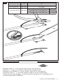
The following steps provide instructions for the connection of either
two PI heating cables or one PI heating cable with a PI cold lead.
Die folgenden Schritte beschreiben die Verbindung entweder zweier
PI-Heizleitungen miteinander oder einer PI-Heizleitung mit einem
PI-Kaltleiter.
Les étapes suivantes donnent les instructions pour la connexion de soit
deux câbles chauffants PI ou soit d’un câble chauffant PI avec un câble
de sortie froide.
De volgende stappen geven aanwijzingen voor het maken van een
verbinding tussen twee verwarmingskabels of een verwarmingskabel en
koudeinde.
Ниже приведены процедуры по сращиванию двух греющих
кабелей с полимерной изоляцией или подсоединения греющего
кабеля с полимерной изоляцией к холодному вводу с полимерной
изоляцией.
~300 mm
1
СВЕДЕНИЯ О ТРАНСПОРТИРОВКЕ И ХРАНЕНИИ
Транспортировать в упаковке можно всеми видами крытых транспортных
средств (автомобильным, железнодорожным, речным, авиационным и др.)
в соответствии с действующими на данном виде транспорта правилами
перевозок при температуре воздуха от – 50°С до + 50°С. Транспортная упаковка
предохраняет корпус от прямого воздействия атмосферных осадков, пыли и
ударов при транспортировании.
Материалы и оборудованиедолжны храниться в сухих и чистых закрытых
помещениях при температуре от –20°С до +40°С и быть защищены от
механических повреждений.

12 | nVent.com/RAYCHEM
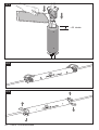
C
When required by the size of the cable the Ø of the hole can be
enlarged. For small size cables use “F” for CS-150-6-PI only.
Falls es die Heizleitungen erfordern, kann der Verschraubungs-Ø
angepasst werden. CS-150-6-PI: Verschraubung F für kleine Kabel-Ø
verwenden.
Dans le cas de câbles de petit diamètre, le diamètre du trou peut être
agrandi. Pour des câbles de petits diamètres utilisés avec le kit
CS-150-6-PI utiliser seulement l’entrée « F ».
Indien vereist kan de doorsnede van het gat worden vergroot. Gebruik
voor kleine kabel doorsnede “F” bij CS-150-6-PI.
Если это необходимо, при большом диаметре кабеля отверстие
для кабеля может быть увеличено. Для кабелей малого диаметра
следует использовать заглушку “F” и набор CS-150-6-PI.
C
F
CS-150-6-PI
2
3


Heizleiter
Schutzgeflecht (metallisch)
Innere Isolation
Schutzmantel
Innere Isolation
Heizleiter
Glasfaser-Geflecht
Schutzmantel
Schutzgeflecht (metallisch)
Innere Isolation
Glasfaser-Geflecht
Glasfaser-Geflecht
Schutzmantel
Schutzgeflecht (metallisch)
Innere Isolation
Schutzgeflecht (metallisch)
Schutzmantel
Polymerfolie
Heizleiter
Heizleiter
Deutsch
Conductor
Braid
Primary Insulation
Outer Insulation
Primary Insulation
Conductor
Glass fibre braiding
Outer Insulation
Braid
Primary Insulation
Braid
Outer Insulation
Polymeric Foil
Primary Insulation
Glass fibre braiding
Conductor
Glass fibre braiding
Outer Insulation
Braid
Conductor
English
CS-150-xx-PI can be used on various cable type
constructions.
CS-150-xx-PI kann für verschiedene Kabelkonstruktionen
verwendet werden.
CS-150-xx-PI peut être utilisé avec différentes
constructions de câble.
The CS-150-xx-PI can only be used with Polymer
Insulated (PI) heating cable types allowed by Thermal
Management.
CS-150-xx-PI darf nur mit von Thermal Management
freigegebenen (PI)-Kabeltypen verwendet werden.
CS-150-xx-PI peut seulement être utilisé avec câble
série à isolation polymère (PI) permis par Thermal
Management.
Conducteur
Tresse
Isolation primaire
Isolation extérieure
Isolation primaire
Conducteur
Tresse en fibre de verre
Isolation extérieure
Tresse
Isolation primaire
Tresse
Isolation extérieure
Ruban polymère
Isolation primaire
Tresse en fibre de verre
Conducteur
Tresse en fibre de verre
Isolation extérieure
Tresse
Conducteur
Français
5A
14 | nVent.com/RAYCHEM

Geleider
Aardingsvlechtwerk
Primaire isolatie
Buitenmantel
Primaire isolatie
Geleider
Glasvezel scherm
Buitenmantel
Aardingsvlechtwerk
Primaire isolatie
Aardingsvlechtwerk
Buitenmantel
Kunststof folie
Primaire isolatie
Glasvezel scherm
Geleider
Glasvezel scherm
Buitenmantel
Aardingsvlechtwerk
Geleider
Nederlands
CS-150-xx-PI kan worden gebruikt op verschillende kabel
constructies.
Набор CS-150-xx-PI может использоваться с греющими
кабелями различных конструкций.
De CS-150-xx-PI kan alleen worden toegepast op
kunststof seriële verwarmingskabels welke zijn
toegelaten door Thermal Management.
Набор CS-150-xx-PI может использоваться
только с теми типами греющих кабелей с
полимерной изоляцией, которые одобрены
Thermal Management.
Токоведущие жилы
Оплетка
Изоляция жил
Внешняя изоляция
Изоляция жил
Токоведущие жилы
Оплетка из стекловолокна
Внешняя изоляция
Оплетка
Изоляция жил
Оплетка
Внешняя изоляция
Полимерная фольга
Изоляция жил
Оплетка из стекловолокна
Токоведущие жилы
Оплетка из стекловолокна
Внешняя изоляция
Оплетка
Токоведущие жилы
Русский
5B
nVent.com/RAYCHEM | 15

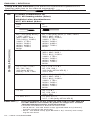
Cable preparation all types
Vorbereitete Heizleitung
Préparation des câbles tous types
Kabel afwerking
Подготовка кабелей всех типов
Conductor
Heizleiter
Conducteur
Geleider
Токоведущая
жила
Braid
Schutzgeflecht
Tresse
Aardingsvlechtwerk
Оплетка
Outer Insulation
Schutzmantel
Isolation extérieure
Buitenmantel
Внешняя изоляция
Primary Insulation
Innere Isolation
Isolation primaire
Primaire isolatie
Изоляция жил
6
16 | nVent.com/RAYCHEM

x
y
x y
CS-150-2.5-PI 30 mm 15 mm
CS-150-6-PI 40 mm 15 mm
CS-150-25-PI 45 mm
PI-CRP-14 -> PI-CRP-17 15 mm
PI-CRP-18 -> PI-CRP-21 18 mm
PI-CRP-22 -> PI-CRP-24 20 mm
Repeat step 2 - 7 for other side of the connection.
Schritt 2 - 7 für das zweite Kabelende wiederholen.
Répéter les étapes 2-7 pour l’autre côté de la connexion.
Herhaal stap 2 – 7 voor de andere zijde van de verbinding.
Повторите процедуры, описанные в пунктах 2-7, для другого
конца греющего кабеля.
7
nVent.com/RAYCHEM | 17

Kit
Possible combinations for
XPI / XPI heating cables (Ω/km)
Crimp type Part number Tool & crimping die
Mögliche Leiter-Kombinationen
XPI / XPI-Kabel (Ω/km)
Verbindertype Bestellnummer Werkzeug und -Einsatz
from
von
to
nach
(10 pieces per pack)
(
10 St./Pck)
Die
Einsatz
Tool
Zange
65 / 100 (only XPI-F)
/ 180 / 200 /
380 / 480 / 600 /
700 / 810 / 1000 /
1440 / 1750 /
2000 / 3000 /
4000 / 4400 /
5600 / 7000 /
8000
65 / 100 (only XPI-F) / 180 / 200 /
380 / 480 / 600 /
700 / 810 / 1000 /
1440 / 1750 /
2000 / 3000 /
4000 / 4400 /
5600 / 7000 /
8000
PI-CRP-01N (*) 1244-016256
CD-PI-02
(Black)
(Schwarz)
PI-TOOL-01 (1224-000549)
CS-150-2.5-PI (1244-000586)
11.7 65 / 100 / 150 / 200 / 320 /
380 / 480 / 600 /
700 / 810 / 1000 /
1440 / 1750 /
2000 / 3000 /
4000 / 4400 /
5600 / 7000 /
8000
PI-CRP-02N (*) 1244-016257
11.7 / 15 / 17.8 /
25 / 50 / 80 /
100 (only XPI &
XPI-S) / 150 / 320
11.7 / 15 / 17.8 /
25 / 50 / 80 /
100 (only XPI & XPI-S) /
150 / 320
PI-CRP-03N (*) 1244-016258
7 / 10 65 / 100 (only XPI-F) / 180 / 200 /
380 / 480 / 600 /
700 / 810 / 1000 /
1440 / 1750 /
2000 / 3000 /
4000 / 4400 /
5600 / 7000 /
8000
PI-CRP-04 1244-016259
7 / 10 15 / 17.8 /
25 / 50 / 80 /
150 / 320
PI-CRP-05 1244-016260
7 / 10 / 11.7 7 / 10 / 11.7 /
31.5 / 100 (only XPI & XPI-S)
PI-CRP-06 1244-016261
ENGLISH / DEUTSCH
Crimp and tool selection (The electrical connection system for PI
heating cable has to be ordered separately).
ENGLISH (*) If the inscriptions on the crimps PI-CRP-01N, PI-CRP-02N and
PI-CRP-03N do not contain 'N', please no longer use. Contact
Thermal Management for more information.
For braid connection in the kit CS-150-2.5-PI:
• XPI & XPI-S : use the braid crimp type BR-CRP-2.5 (2.5mm²)
and the crimping die CD-PI-02.
• XPI-F : use braid crimp type BR-CRP-1.5 (1.5mm²) and crimp-
ing die CD-PI-02
Table / Tabelle 1: PI-TOOL-SET-01 ≤ 2,5 mm²
18 | nVent.com/RAYCHEM

Kit
Possible combinations for
XPI / XPI heating cables (Ω/km)
Crimp type Part number Tool & crimping die
Mögliche Leiter-Kombinationen
XPI / XPI-Kabel (Ω/km)
Verbindertype Bestellnummer Werkzeug und -Einsatz
from
von
to
nach
(10 pieces per pack)
(
10 St./Pck)
Die
Einsatz
Tool
Zange
65 / 100 (only XPI-F)
/ 180 / 200 /
380 / 480 / 600 /
700 / 810 / 1000 /
1440 / 1750 /
2000 / 3000 /
4000 / 4400 /
5600 / 7000 /
8000
65 / 100 (only XPI-F) / 180 / 200 /
380 / 480 / 600 /
700 / 810 / 1000 /
1440 / 1750 /
2000 / 3000 /
4000 / 4400 /
5600 / 7000 /
8000
PI-CRP-01N (*) 1244-016256
CD-PI-02
(Black)
(Schwarz)
PI-TOOL-01 (1224-000549)
CS-150-2.5-PI (1244-000586)
11.7 65 / 100 / 150 / 200 / 320 /
380 / 480 / 600 /
700 / 810 / 1000 /
1440 / 1750 /
2000 / 3000 /
4000 / 4400 /
5600 / 7000 /
8000
PI-CRP-02N (*) 1244-016257
11.7 / 15 / 17.8 /
25 / 50 / 80 /
100 (only XPI &
XPI-S) / 150 / 320
11.7 / 15 / 17.8 /
25 / 50 / 80 /
100 (only XPI & XPI-S) /
150 / 320
PI-CRP-03N (*) 1244-016258
7 / 10 65 / 100 (only XPI-F) / 180 / 200 /
380 / 480 / 600 /
700 / 810 / 1000 /
1440 / 1750 /
2000 / 3000 /
4000 / 4400 /
5600 / 7000 /
8000
PI-CRP-04 1244-016259
7 / 10 15 / 17.8 /
25 / 50 / 80 /
150 / 320
PI-CRP-05 1244-016260
7 / 10 / 11.7 7 / 10 / 11.7 /
31.5 / 100 (only XPI & XPI-S)
PI-CRP-06 1244-016261
Preßverbinder- und Werkzeug-Auswahl (die Leiter-Verbinder der
Heizkabel müssen separat bestellt werden).
DEUTSCH (*) Wenn die Inschriften auf den Crimp-Verbindern PI-CRP-01N,
PI-CRP-02N und PI-CRP-03N kein „N“ enthalten, so sind diese
nicht mehr zu verwenden. Weitere Informationen erhalten Sie
bei Thermal Management.
Zum Anschluss des Schutzgeflechts im Bausatz CS-150-2.5-PI:
•
XPI und XPI-S: Schutzgeflecht-Crimp des Typs BR-CRP-2.5 (2,5 mm²)
und Crimpzangeneinsatz CD-PI-02 verwenden.
•
XPI-F: Schutzgeflecht-Crimp des Typs BR-CRP-1.5 (1,5 mm²) und
Crimpzangeneinsatz CD-PI-02 verwenden
nVent.com/RAYCHEM | 19

FRANÇAIS / NEDERLANDS
Sélection des cosses et des outils (le système de connexion électrique des
câbles PI doit être commandé séparément).
Tableau / Tabel 1: PI-TOOL-SET-01 ≤ 2,5 mm²
FRANÇAIS (*) Si les références des cosses PI-CRP-01N, PI-CRP-02N et
PI-CRP-03N ne se terminent pas par ‘N’, ne les utilisez pas
et veuillez demander conseil a votre represantant Thermal
Management.
Pour le raccordement de tresses du kit CS-150-2.5-PI :
• XPI et XPI-S : utiliser l’outil de sertissage pour tresse réf.
BR-CRP-2.5 (2,5 mm²) et la matrice réf. CD-PI-02.
• XPI-F : utiliser l’outil de sertissage pour tresse réf. BR-CRP-1.5
(1,5mm²) et la matrice réf. CD-PI-02.
Kit
Combinaisons possibles pour XPI /
Câble chauffants XPI (Ω/km)
Type de Cosses Référence
pièce
Outil et matrice
de sertissage
Mogelijke combinaties van
XPI / XPI verwarmingskabel (Ω/km)
Verbindertype Bestelnummer Krimptool en inzet
de
van
à
tot
(10 pièces par sachet)
(
10 stuks per zakje)
Matrice
Inzet
Outil
Tang
65 / 100 (only XPI-F)
/ 180 / 200 /
380 / 480 / 600 /
700 / 810 / 1000 /
1440 / 1750 /
2000 / 3000 /
4000 / 4400 /
5600 / 7000 /
8000
65 / 100 (only XPI-F) / 180 / 200 /
380 / 480 / 600 /
700 / 810 / 1000 /
1440 / 1750 /
2000 / 3000 /
4000 / 4400 /
5600 / 7000 /
8000
PI-CRP-01N (*) 1244-016256
CD-PI-02
(Noir)
(Zwart)
PI-TOOL-01 (1224-000549)
CS-150-2.5-PI (1244-000586)
11.7 65 / 100 / 150 / 200 / 320 /
380 / 480 / 600 /
700 / 810 / 1000 /
1440 / 1750 /
2000 / 3000 /
4000 / 4400 /
5600 / 7000 /
8000
PI-CRP-02N (*) 1244-016257
11.7 / 15 / 17.8 /
25 / 50 / 80 /
100 (only XPI &
XPI-S) / 150 / 320
11.7 / 15 / 17.8 /
25 / 50 / 80 /
100 (only XPI & XPI-S) /
150 / 320
PI-CRP-03N (*) 1244-016258
7 / 10 65 / 100 (only XPI-F) / 180 / 200 /
380 / 480 / 600 /
700 / 810 / 1000 /
1440 / 1750 /
2000 / 3000 /
4000 / 4400 /
5600 / 7000 /
8000
PI-CRP-04 1244-016259
7 / 10 15 / 17.8 /
25 / 50 / 80 /
150 / 320
PI-CRP-05 1244-016260
7 / 10 / 11.7 7 / 10 / 11.7 /
31.5 / 100 (only XPI & XPI-S)
PI-CRP-06 1244-016261
20 | nVent.com/RAYCHEM
La page est en cours de chargement...
La page est en cours de chargement...
La page est en cours de chargement...
La page est en cours de chargement...
La page est en cours de chargement...
La page est en cours de chargement...
La page est en cours de chargement...
La page est en cours de chargement...
La page est en cours de chargement...
La page est en cours de chargement...
La page est en cours de chargement...
La page est en cours de chargement...
La page est en cours de chargement...
La page est en cours de chargement...
La page est en cours de chargement...
La page est en cours de chargement...
La page est en cours de chargement...
La page est en cours de chargement...
La page est en cours de chargement...
La page est en cours de chargement...
La page est en cours de chargement...
La page est en cours de chargement...
La page est en cours de chargement...
La page est en cours de chargement...
-
 1
1
-
 2
2
-
 3
3
-
 4
4
-
 5
5
-
 6
6
-
 7
7
-
 8
8
-
 9
9
-
 10
10
-
 11
11
-
 12
12
-
 13
13
-
 14
14
-
 15
15
-
 16
16
-
 17
17
-
 18
18
-
 19
19
-
 20
20
-
 21
21
-
 22
22
-
 23
23
-
 24
24
-
 25
25
-
 26
26
-
 27
27
-
 28
28
-
 29
29
-
 30
30
-
 31
31
-
 32
32
-
 33
33
-
 34
34
-
 35
35
-
 36
36
-
 37
37
-
 38
38
-
 39
39
-
 40
40
-
 41
41
-
 42
42
-
 43
43
-
 44
44


Raychem CS-150-xx-PI Guide d'installation
- Taper
- Guide d'installation
Documents connexes
-
Raychem Câble PI Guide d'installation
-
-
-
-
Raychem Raychem ETS-05-L2-EP Guide d'installation
-
-
-
-
-
Autres documents
-
3M QS-II Molded Rubber Inline Splice Kit 5420, CN and JCN, 25/28 kV, 2-1/0 AWG, 0.795-0.940 in, 1/case Mode d'emploi
-
PRAXISDIENST Actim Manuel utilisateur
-
 Palram 704578 Guide d'installation
-
 Palram 704574 Guide d'installation
-
Hama 00087689 Le manuel du propriétaire
-
nvent VARISTAR Manuel utilisateur
-
Gima 24605 Le manuel du propriétaire
-
Eaton Crouse-Hinds GHG 960 1944 R Series Operating Instructions Manual

